JP2017170802A - Press-bonded sheet - Google Patents
Press-bonded sheet Download PDFInfo
- Publication number
- JP2017170802A JP2017170802A JP2016060693A JP2016060693A JP2017170802A JP 2017170802 A JP2017170802 A JP 2017170802A JP 2016060693 A JP2016060693 A JP 2016060693A JP 2016060693 A JP2016060693 A JP 2016060693A JP 2017170802 A JP2017170802 A JP 2017170802A
- Authority
- JP
- Japan
- Prior art keywords
- pressure
- sensitive adhesive
- base material
- sheet
- adhesive layer
- Prior art date
- Legal status (The legal status is an assumption and is not a legal conclusion. Google has not performed a legal analysis and makes no representation as to the accuracy of the status listed.)
- Pending
Links
Images




Landscapes
- Credit Cards Or The Like (AREA)
Abstract
Description
本発明は、圧着シートに関し、更に詳しくは、感圧接着層を有する基材が、該基材に設けられた折部にて折られて重なることにより、感圧接着層同士が重なり、感圧接着層により圧着する圧着シートに関するものである。 The present invention relates to a pressure-sensitive adhesive sheet, and more specifically, a base material having a pressure-sensitive adhesive layer is folded and overlapped at a folding portion provided on the base material, whereby the pressure-sensitive adhesive layers are overlapped with each other. The present invention relates to a pressure-bonding sheet that is pressure-bonded by an adhesive layer.
個人情報等が印刷された圧着可能なシートがある。この圧着シートは、シート部を構成する基材の少なくとも一部に粘着剤が塗布されており、その粘着剤面にデザイン等の印刷や個人情報等の印刷がなされて、粘着剤面同士が重なるように折部にて圧着することにより、剥離可能に圧着することができる。圧着シートを受け取った人は、折部以外の縁部のいずれかより、めくり開くことで重なった粘着剤面を閲覧することが可能となる。 There is a crimpable sheet on which personal information is printed. In this pressure-bonded sheet, a pressure-sensitive adhesive is applied to at least a part of the base material constituting the sheet portion, and the pressure-sensitive adhesive surface is overlapped by printing such as design or personal information on the pressure-sensitive adhesive surface. Thus, by crimping at the folded portion, it is possible to perform crimping in a peelable manner. The person who has received the pressure-bonded sheet can view the pressure-sensitive adhesive surface overlapped by turning open from any edge other than the folded portion.
圧着シートの縁部は、製造により裁断されており、裁断面が完全な均一面ではなく、微妙に亀裂や歪みが生じている。また圧着シートをはがきとして利用し、郵送するなどした際に、やはり縁部にキズや歪みが発生することも少なくない。圧着シートや圧着シートのはがきを受け取った人がめくり開く際に、裁断面の一部に発生した亀裂やキズ、歪みに沿って破れ、粘着剤面がきれいに剥がれないことがある。 The edge portion of the pressure-bonded sheet is cut by manufacturing, and the cut surface is not a completely uniform surface, but is slightly cracked or distorted. Also, when using a pressure-bonded sheet as a postcard and mailing it, it is not uncommon for scratches and distortions to occur at the edges. When a person who receives a postcard of a pressure-bonded sheet or a pressure-bonded sheet turns over, the pressure-sensitive adhesive surface may not be peeled off cleanly due to tearing along cracks, scratches and distortions that occur in a part of the cut surface.
圧着シートの粘着剤面をきれいに剥がすことを可能にする発明としては、例えば特許文献1が既に開示されている。特許文献1で開示されている発明において、圧着シートと同様な用途を有する粘着シートの縁部に「糊殺し」と呼ばれる粘着剤の効力を弱める部分を設けることで、粘着シートをめくり開く際に粘着剤面に掛かる力が、縁部の亀裂やキズ、歪みに掛かる力を弱めることのできる糊殺し粘着シートの製造方法および糊殺し粘着シートである。
As an invention that makes it possible to cleanly remove the pressure-sensitive adhesive surface of the pressure-bonding sheet, for example,
しかしながら、上記特許文献1に記載の粘着シートでは、糊殺し剤として印刷インキあるいはニスが用いられており、印刷インキやニスを用いるための材料のコストアップや、糊殺し部に印刷インキによる印刷やニスを塗布するスペースが必要となり、粘着剤面のデザインや個人情報の印刷内容に制約を受けることがある。
However, in the pressure-sensitive adhesive sheet described in
そこで本発明は、粘着剤面に印刷するデザインや個人情報等になんら制約させることなく、さらに糊殺し剤等を用いることなく、粘着シートの縁部に粘着剤の効力を弱める部分を形成することができるようにすることを目的とする。 Therefore, the present invention forms a portion that weakens the effect of the adhesive on the edge of the adhesive sheet without restricting the design or personal information printed on the adhesive surface, and without using a paste-killing agent. The purpose is to be able to.
本発明に係わる圧着シートおよび圧着シートの製造方法は、以下の各発明により上記課題を解決した。なお以下の各発明には参照のために付した括弧内の符号は、後述する実施形態および図面に付した符号と対応しているが、本発明は実施形態に限られない。 The pressure-sensitive adhesive sheet and the method for manufacturing the pressure-sensitive adhesive sheet according to the present invention solve the above-described problems by the following inventions. In addition, although the code | symbol in the parenthesis attached | subjected for reference to each following invention respond | corresponds with the code | symbol attached to embodiment and drawing which are mentioned later, this invention is not limited to embodiment.
本発明に係わる第1の発明は、基材の一方の面に感圧接着層が設けられ、前記基材は前記感圧接着層を内側にして一つの折部で折られた基材のうち、一方の基材は他方の基材の一辺から延出した表出面を有しており、前記一方の基材の表出面側であって、前記表出面を含み前記他方の基材の一辺を跨ぐ領域の基材および感圧接着層が圧縮されていることを特徴とする圧着シートである。 In a first aspect of the present invention, a pressure-sensitive adhesive layer is provided on one surface of a base material, and the base material is a base material folded in one fold with the pressure-sensitive adhesive layer inside. The one substrate has an exposed surface extending from one side of the other substrate, and is on the exposed surface side of the one substrate, and includes one surface of the other substrate including the exposed surface. The pressure-sensitive adhesive sheet is characterized in that the base material and the pressure-sensitive adhesive layer in the straddling region are compressed.
第1の発明の圧着シートによれば、圧着シートの裁断部(20)に沿って基材(10)および感圧接着層(11)が圧縮されることにより圧縮部(12)が形成されるため、圧縮されていない感圧接着層(11)同士が折られて重なり圧着される部分に比べて、圧縮されている部分の圧着力が弱まり、接着力を弱める部分を形成することができる。
したがって、第1の発明の圧着シートを受け取った人が圧着シートの裁断部(20)よりめくり開く際に、裁断部(20)に亀裂やキズ、歪みがあっても、接着力が弱い事により、亀裂やキズ、歪みに掛かる力が弱まり、粘着剤面をきれいに剥がすことができる。
According to the pressure-sensitive adhesive sheet of the first invention, the compressed portion (12) is formed by compressing the base material (10) and the pressure-sensitive adhesive layer (11) along the cut portion (20) of the pressure-sensitive adhesive sheet. Therefore, compared to the portion where the non-compressed pressure-sensitive adhesive layers (11) are folded and overlapped and crimped, the compression force of the compressed portion is weakened, and a portion that weakens the adhesive force can be formed.
Therefore, when the person who receives the pressure-sensitive adhesive sheet of the first invention turns over from the cutting part (20) of the pressure-bonding sheet, even if the cutting part (20) has cracks, scratches, or distortion, the adhesive strength is weak. , Cracks, scratches, distortion, and the adhesive surface can be peeled off.
本発明に係わる第2の発明は、基材の両方の面に感圧接着層が設けられ、前記基材は前記感圧接着層を内側にして二つの折部でZ字状に折られた前記折部を境に区分される基材のうち、中央に位置する基材は両端に位置するそれぞれの基材の一辺から延出した表出面を有しており、
前記中央に位置する基材の表出面側であって、前記表出面を含み前記両端に位置するそれぞれの基材の一辺を跨ぐ領域の基材および感圧接着層が圧縮されていることを特徴とする圧着シート。
According to a second aspect of the present invention, a pressure-sensitive adhesive layer is provided on both sides of the base material, and the base material is folded in a Z-shape at two folds with the pressure-sensitive adhesive layer inside. Of the base materials divided at the folding part, the base material located in the center has an exposed surface extending from one side of each base material located at both ends,
The base material and the pressure-sensitive adhesive layer are compressed on the exposed surface side of the base material located at the center and straddling one side of each base material including the exposed surface and located at both ends. A crimping sheet.
第2の発明の圧着シートによれば、圧着シートの裁断部(20)に沿って基材(10)および感圧接着層(11)が圧縮されることにより圧縮部(12)が形成されるため、圧縮されていない感圧接着層(11)同士が折られて重なり圧着される部分に比べて、圧縮されている部分の圧着力が弱まり、接着力を弱める部分を形成することができる。
したがって、第2の発明の圧着シートを受け取った人が圧着シートの裁断部(20)よりめくり開く際に、裁断部(20)に亀裂やキズ、歪みがあっても、接着力が弱い事により、亀裂やキズ、歪みに掛かる力が弱まり、粘着剤面をきれいに剥がすことができる。
According to the pressure-sensitive adhesive sheet of the second invention, the compressed portion (12) is formed by compressing the base material (10) and the pressure-sensitive adhesive layer (11) along the cut portion (20) of the pressure-sensitive adhesive sheet. Therefore, compared to the portion where the non-compressed pressure-sensitive adhesive layers (11) are folded and overlapped and crimped, the compression force of the compressed portion is weakened, and a portion that weakens the adhesive force can be formed.
Therefore, when the person who receives the pressure-sensitive adhesive sheet of the second invention turns over from the cutting part (20) of the pressure-sensitive adhesive sheet, even if the cutting part (20) has cracks, scratches, or distortion, the adhesive strength is weak. , Cracks, scratches, distortion, and the adhesive surface can be peeled off.
第3の発明は、上記第1または第2の発明において、前記基材(10)の所定の位置に設けられた貫通孔(24)により、前記折部で折られて重なる面の一部が圧着後に視認できることを特徴とするものである。 According to a third aspect of the present invention, in the first or second aspect of the present invention, a part of the surface that is folded and overlapped by the folding portion is formed by the through hole (24) provided at a predetermined position of the base material (10). It is characterized by being visible after crimping.
第3の発明の圧着シートによれば、圧着シートを郵便はがきとして利用するため、基材(10)の所定の位置に設けられた貫通孔(24)により、折部で折られて重なる面に印刷された「郵便はがき」の文字が視認できる。
したがって、第3の発明の圧着シートは、郵便はがきとして利用することができる。
According to the pressure-sensitive adhesive sheet of the third invention, since the pressure-sensitive adhesive sheet is used as a postcard, the surface is folded and overlapped by the folding portion by the through hole (24) provided at a predetermined position of the base material (10). The printed letters of “postcard” are visible.
Therefore, the pressure-sensitive adhesive sheet of the third invention can be used as a postcard.
第4の発明は、上記第1または第2の発明において、前記折部で折られて重なる前記基材(10)は、一端が短いことで重なる面の一部が圧着後に視認できることを特徴とするものである。 According to a fourth aspect of the present invention, in the first or second aspect, the base material (10) folded and overlapped at the folding portion has a short one end so that a part of the overlapping surface can be visually recognized after pressure bonding. To do.
第4の発明の圧着シートによれば、圧着シートを郵便はがきとして利用するため、基材(10)は一端を短くして折られて圧着されることで、重なる面の一部に印刷された「郵便はがき」の文字が視認できる。
したがって、第4の発明の圧着シートは、郵便はがきとして利用することができる。
According to the pressure-sensitive adhesive sheet of the fourth invention, since the pressure-sensitive adhesive sheet is used as a postcard, the base material (10) is printed on a part of the overlapping surface by being folded and crimped with one end shortened. The letter “postcard” is visible.
Therefore, the pressure-sensitive adhesive sheet of the fourth invention can be used as a postcard.
本発明に係わる第5の発明は、上記第1〜第4のいずれかの発明において、コーナー部(25)もしくはコーナーカット部(26)に、前記基材(10)および前記感圧接着層(11)が圧縮されていることを特徴とするものである。 According to a fifth aspect of the present invention, in any of the first to fourth aspects of the present invention, the base (10) and the pressure-sensitive adhesive layer ( 11) is compressed.
第5の発明の圧着シートによれば、コーナー部(25)もしくはコーナーカット部(26)が圧縮されているため、圧縮されていない感圧接着層(11)同士が折られて重なり圧着される部分に比べて、圧縮されている部分の圧着力が弱まり、接着力を弱めるコーナー部(25)もしくはコーナーカット部(26)を形成することができる。 According to the pressure-sensitive adhesive sheet of the fifth invention, since the corner portion (25) or the corner cut portion (26) is compressed, the non-compressed pressure-sensitive adhesive layers (11) are folded and overlapped for pressure bonding. Compared with the portion, the pressure-bonding force of the compressed portion is weakened, and the corner portion (25) or the corner cut portion (26) that weakens the adhesive force can be formed.
したがって、第5の発明の圧着シートを受け取った人が圧着シートのコーナー部もしくはコーナーカット部よりめくり開く際に、コーナー部もしくはコーナーカット部から粘着剤面をきれいに剥がすことができる。 Therefore, when the person who receives the pressure-sensitive adhesive sheet of the fifth invention turns over from the corner portion or the corner cut portion of the pressure-bonded sheet, the adhesive surface can be peeled cleanly from the corner portion or the corner cut portion.
本発明によれば粘着剤面に印刷するデザインや個人情報等になんら制約させることなく、さらに糊殺し剤等を用いることなく、粘着シートの縁部に粘着剤の効力を弱める部分を形成することができる。そのため圧着シートの生産性が向上する。 According to the present invention, without restricting the design or personal information printed on the pressure-sensitive adhesive surface, and without using a paste-killing agent or the like, a portion that weakens the effectiveness of the pressure-sensitive adhesive is formed on the edge of the pressure-sensitive adhesive sheet. Can do. Therefore, the productivity of the pressure-bonded sheet is improved.
本発明の各実施形態について図面を参照して詳述する。 Each embodiment of the present invention will be described in detail with reference to the drawings.
(実施形態1)
まず本実施形態1について説明する。
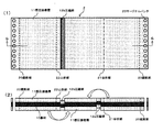
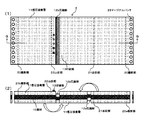
図1は、本実施形態1に係わる圧着シート1の概略図の一例である。
図1(1)は、圧着シート1を上面から見た図である。
図1(2)は、図1(1)のE−E矢視断面図である。
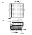
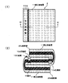
図2(1)は、図1(1)の圧着シート1の圧着後の状態を説明する図である。
図2(2)は、図2(1)のF−F矢視断面図である。
(Embodiment 1)
First, the first embodiment will be described.
FIG. 1 is an example of a schematic view of a pressure-
FIG. 1A is a view of the pressure-
FIG. 1B is a cross-sectional view taken along the line E-E in FIG.
FIG. 2A is a diagram for explaining a state after the pressure-
FIG. 2B is a cross-sectional view taken along the line FF in FIG.
図1(1)に示すように実施形態1は、基材の一方の面に感圧接着層が設けられ、前記基材は前記感圧接着層を内側にして一つの折部で折られた基材のうち、一方の基材は他方の基材の一辺から延出した表出面を有しており、前記一方の基材の表出面側であって、前記表出面を含み前記他方の基材の一辺を跨ぐ領域の基材および感圧接着層が圧縮されていることを特徴とする圧着シートである。
即ち、基材10の一方の面のみに感圧接着層11が形成されており、この感圧接着層11が内側になるように基材10を二つ折りするタイプの圧着シートである(図1(2)のE−E矢視断面図を参照)。
さらに印刷機等の装置でズレなく基材10をピン送りできるよう表裏で貫通しているマージナルパンチ23が基材10の両側の所定位置に設けられている。印刷機等の装置では、マージナルパンチ23と嵌合するように凸状部を設けたローラー等により、基材10を送る仕組みを持つ(図示なし)。
なお、図1では説明の便宜ため、裁断部20a、裁断部20b、谷折部21が破線等で図示されているが、実際には印刷等がされておらず、検査の目的などで線の一部が目印程度に印刷されている。
As shown in FIG. 1 (1), in
That is, the pressure-
Further, marginal punches 23 penetrating on the front and back sides are provided at predetermined positions on both sides of the base material 10 so that the base material 10 can be pin-fed without deviation by an apparatus such as a printing press. An apparatus such as a printing machine has a mechanism for feeding the substrate 10 by a roller or the like provided with a convex portion so as to be fitted to the marginal punch 23 (not shown).
In FIG. 1, for convenience of explanation, the cutting portion 20a, the cutting portion 20b, and the
圧縮部12は、基材10上に感圧接着層11が設けられた後に、ローラーや金型等により圧縮され、基材10と感圧接着層11が圧縮された部分である。圧縮部12は、裁断部20aから所定間隔を置き、かつ前記裁断部20aに沿って帯状に形成される。圧縮部12は、前記谷折部21から基材を折り畳んだ際に、裁断部20bの端部が前記圧縮部12の中央付近となる位置に形成する。圧縮部12の幅は、多少のズレを考慮して形成する。
なお、マージナルパンチ23を含む断裁領域は、管理情報を印刷する余白として製品を製造する上で必要ではあるが、最終製品においては不要な部分であるから裁断部20a、裁断部20bで断裁される。
The compressing unit 12 is a portion in which the base 10 and the pressure-
The cutting area including the marginal punch 23 is necessary for manufacturing a product as a margin for printing management information, but is cut by the cutting unit 20a and the cutting unit 20b because it is an unnecessary part in the final product. .
図2(1)は、図1(1)の圧着シート1を圧着した後の状態であって、かつ裁断部20a、裁断部20bにより断裁領域を断裁した後の状態を示している。また、図2(2)は図2(1)のF−F矢視断面図を表している。厚さ方向は説明し易いように誇張して描かれている。圧縮部12は、後述のローラーや金型等により圧縮された後、基材10や感圧接着層11の弾性作用により多少の復元はあるが、略凹状になる。
圧縮部12を形成した後の圧着シート1は、谷折部21で谷折りにされ、左右の感圧接着層11同士を圧着する。この圧着により、基材10もしくは感圧接着層11に、印刷機等により印刷された情報やプリンタ等によるオンデマンドプリントにより印字された情報が、折面の内側となり、情報が隠蔽されることになる。
FIG. 2 (1) shows a state after the pressure-
After the compression part 12 is formed, the pressure-
圧縮部12は、感圧接着層11のある他の面に比べて略凹状となっているので、圧着後の圧着シート1では多少の隙間があるか、もしくは圧縮部12の接着力は圧縮部12以外の圧着面に比べて弱い接着力にて圧着される。
Since the compression part 12 is substantially concave compared to the other surface having the pressure-
圧着シート1は製造後、郵送等により受取人へ送付され、受取人が開封する際には、裁断部20bと圧縮部12との間より剥離することで開封できる。圧縮部12による感圧接着層11の接着力は、感圧接着層11の圧着面に多少の隙間があるか、もしくは圧縮部12以外の圧着面に比べて弱い接着力にて圧着されている。さらに、基材10が圧縮されることにより、圧縮部12の基材10に対する強度が上がる。そのため、裁断部20bでの裁断面にキズや折れ等で基材10が破れ易くなっていても、剥離の際に基材10のキズや折れ等が広がることなく、感圧接着層11同士の接着面より剥がし、隠蔽された面の情報を閲覧することができる。
The pressure-
また図示してないが、基材10に印刷または印字された情報が、郵便配達中などの取扱い中に、それらの情報が透けて見えないように、基材10の感圧接着層11の設けられた面と反対面や、基材10と感圧接着層11との間に、地紋印刷を施こすことが好ましい。
Although not shown, the pressure-
以下に、本実施形態の圧着シート1を構成する要素について、詳しく説明する。
(基材)
圧着シート1の基材10として、例えば、上質紙、アート紙、コート紙、キャストコート紙、合成樹脂又はエマルジョン含浸紙、合成ゴムラテックス含浸紙、合成樹脂内添紙、セルロース繊維紙等の紙類、または基材内部に微細空隙(ミクロボイド)を有するフィルム(いわゆる合成紙)を使用することができる。
Below, the element which comprises the crimping | compression-
(Base material)
Examples of the base material 10 of the pressure-
(感圧接着層)
感圧接着層11は、その使用する感圧接着層11が基材10と接触しても接着せずに、感圧接着層11同士が加圧接触してはじめて接着し、しかも再剥離ができるように調整されたものである。
感圧接着層11を構成する感圧接着剤としては、以下に説明する接着主剤と充填剤を含有させたものが使用できる。その接着主剤としては、天然ゴムを無硫黄加硫し、メタアクリル酸メチルと混合した天然ゴムラテックス、天然ゴムにメタアクリル酸メチルやスチレンモノマー等をグラフト共重合させて得られた天然ゴムラテックスが挙げられる。
(Pressure sensitive adhesive layer)
The pressure-
As the pressure-sensitive adhesive constituting the pressure-
感圧接着剤に含有する充填剤としては、例えば、クレー、一次または二次凝集体を形成しているカルサイト系沈降性炭酸カルシウム、二次凝集体を形成しているアラゴナイト系沈降性炭酸カルシウム、炭酸カルシウム、スチレンビーズ、シリカ、合成微粒子シリカ、アミノ表面改質シリカ、ワックス表面処理シリカ、球状シリカ、通常のカルシウムや、亜鉛、マグネシウム、アルミニウムもしくはチタン等の金属の酸化物、水酸化物、炭酸塩、珪酸塩、またはこれらの混合物等が挙げられる。好適には、クレーと炭酸カルシウムである。 Examples of the filler contained in the pressure-sensitive adhesive include clay, calcite-based precipitated calcium carbonate forming primary or secondary aggregates, and aragonite-based precipitated calcium carbonate forming secondary aggregates. , Calcium carbonate, styrene beads, silica, synthetic fine particle silica, amino surface modified silica, wax surface treated silica, spherical silica, ordinary calcium, metal oxides such as zinc, magnesium, aluminum or titanium, hydroxides, Examples thereof include carbonates, silicates, and mixtures thereof. Preferred are clay and calcium carbonate.
感圧接着剤には、上記の接着主剤、充填剤、その他、必要に応じて分散剤、印刷適性向上剤等の添加剤なども目的に応じて併用することができる。
基材10への感圧接着剤の塗工は、従来既知の塗工方法により塗工することができる。
例えば、エアーナイフコーター、ロールコーター、ブレードコーター、ロッドブレードコーター、バーコーター、ダイコーター等の一般的なコーターによって塗工されるが、塗工量は固形分で3〜15g/m2の範囲で調整されるのが望ましい。
塗工量が3g/m2の未満であると、所望の接着力が得られず意図しない剥離が生じやすくなり、15g/m2を超えると、接着力が強くなりすぎて、剥離することができなくなったり、塗工時に塗工ロールに、接着剤の粕が付着したりして、操業上および品質上のトラブルが生じやすくなる。
In the pressure-sensitive adhesive, the above-mentioned adhesive main agent, filler, and other additives such as a dispersant and a printability improver can be used in combination according to the purpose.
The pressure-sensitive adhesive can be applied to the substrate 10 by a conventionally known coating method.
For example, it is applied by a general coater such as an air knife coater, roll coater, blade coater, rod blade coater, bar coater, die coater, etc., but the coating amount is in the range of 3 to 15 g / m 2 in terms of solid content. It is desirable to be adjusted.
If the coating amount is less than 3 g / m 2 , the desired adhesive force cannot be obtained, and unintended peeling tends to occur. If the coating amount exceeds 15 g / m 2 , the adhesive force becomes too strong and may peel off. It becomes impossible, or adhesive wrinkles adhere to the coating roll at the time of coating, and operational and quality problems are likely to occur.
以下に、圧着シート1の製造方法について説明する。
圧着シート1の基材10に対し、感圧接着層11と、印刷部(図示なし)を形成する。その感圧接着層11と印刷部との形成する順序は、特に限定するものではない。なお基材10の一方(上面または下面)の全面に、感圧接着層11が塗工されたものを入手する場合は、印刷部の形成は後で行なうことになる。
この印刷部の形成は、グラビア印刷やオフセット印刷等の印刷で形成する、またはインクジェット記録、電子写真記録などのプリンタで、圧着シート1に個人情報など可変データを記録する際に、「郵便はがき」や「連絡票」などの表示を行なうための記録も兼ねて行なうことも可能である。
Below, the manufacturing method of the crimping | compression-
A pressure-
This printing part is formed by printing such as gravure printing or offset printing, or “postcard” when recording variable data such as personal information on the pressure-
次に、圧着シート1の所定の箇所に、谷折部21または裁断部20を、ミシン加工により、形成する。その際に、連続シートの基材10を用いて、長尺の形態で連続的に加工することが大量生産上好ましく、その連続シートの搬送方向で、両端にマージナルパンチ23を、一対のロール表面に、ピンとダイスを取り付けて、ロール同士が基材10を間に挟んで回転することで、マージナルパンチ23を打ち抜いて加工することが好ましい。また必要に応じてコーナーカット部を打ち抜き加工により形成してもよい(図示なし)。ただし、ピンとダイスの噛み合う形状を、コーナーカットの形状(三角形)に変更することが必要である。
Next, the
上記の基材10上に、感圧接着層11と、印刷部を形成し、さらに谷折部21または裁断部20を形成し、主に裁断部20を跨ぐようにして、ローラーや金型等により基材10及び感圧接着層11を圧縮して圧縮部12を形成し、接着力を低下させ、その後に基材10を谷折部21で折り重ねて、または裁断部20で基材10を切り取り、切り取られた基材10同士を重ねて、感圧接着層11同士により、圧着し接着させた。
A pressure-
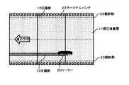
次に、圧縮部12を形成する方法について、説明する。
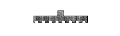
図9は、本実施形態1の圧着シート1の圧縮部12を形成する一例である。図9において、基材10は連続シートとなっており、基材10上に、感圧接着層11、印刷部(図示なし)、裁断部20等が形成された後に、感圧接着層11の面に対して連続シートの動きに合わせてローラー30を回転させながら押し当てて、基材10および感圧接着層11を圧縮し、圧縮部12を形成する。圧縮した際に、略凹部が形成されるが、圧縮前と比べて50〜400μm程度、好ましくは200μm程度の窪みになるよう圧縮力を設定する。
Next, a method for forming the compression unit 12 will be described.
FIG. 9 is an example of forming the compression part 12 of the pressure-
(本実施形態1の作用効果)
以上のように本実施形態1によれば、隠蔽される感圧接着層11の面に対して、デザインや個人情報等になんら制約させることなく印刷をすることができ、糊殺し剤等を用いることなく、粘着シートの縁部に粘着剤の効力を弱める部分を形成することができる。
さらに、基材10が圧縮された圧縮部12は、圧縮されていない基材10より強度が高くより破れにくいため、圧着シート1を受け取った人が圧縮部12よりめくり開く際に、亀裂やキズがあっても破れが広がることなく、粘着剤面をきれいに剥がすことができる。
なお、圧縮されている部分には、隙間を形成することもできる。
(Operational effect of the first embodiment)
As described above, according to the first embodiment, the surface of the pressure-
Further, since the compressed portion 12 in which the base material 10 is compressed is stronger and more difficult to break than the uncompressed base material 10, when the person who receives the pressure-
A gap can also be formed in the compressed portion.
(実施形態2)
実施形態1は、基材10の一方の面のみに感圧接着層11が形成され、この感圧接着層11が内側になるように基材10を二つ折りするタイプの圧着シートであった。
(Embodiment 2)
The first embodiment is a pressure-bonding sheet in which the pressure-
これに対して、実施形態2は、基材の両方の面に感圧接着層が設けられ、前記基材は前記感圧接着層を内側にして二つの折部でZ字状に折られた前記折部を境に区分される基材のうち、中央に位置する基材は両端に位置するそれぞれの基材の一辺から延出した表出面を有しており、前記中央に位置する基材の表出面側であって、前記表出面を含み前記両端に位置するそれぞれの基材の一辺を跨ぐ領域の基材および感圧接着層が圧縮されていることを特徴とする圧着シートである。
即ち、実施形態2においては、折部が谷折部21と山折部22との2箇所に形成されており、谷折部21では谷折り、山折部22では山折りで折り重ねた際に3紙面が折り重なる、いわゆるZ折と呼ばれる圧着シートである。
以下、実施形態1と異なる点を中心に実施形態2について説明する。
In contrast, in
That is, in the second embodiment, the folding part is formed at two places, the
Hereinafter, the second embodiment will be described with a focus on differences from the first embodiment.
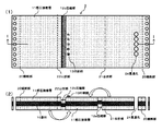
図3は、実施形態2の圧着シート2の圧着前の状態を説明する図である。
図3(1)は、圧着シート2を上面から見た図である。
図3(2)は、図3(1)のG−G矢視断面図である。
図4は、実施形態2の圧着シート2の圧着後の状態を説明する図である。
図4(1)は、圧着後の圧着シート2を上面から見た図である。
図4(2)は、図4(1)のH−H矢視断面図である。
FIG. 3 is a diagram for explaining a state before pressure bonding of the pressure-
FIG. 3A is a view of the pressure-
FIG. 3B is a cross-sectional view taken along the line GG in FIG.
FIG. 4 is a diagram for explaining a state after the crimping of the crimping
FIG. 4 (1) is a view of the pressure-bonded
FIG. 4B is a cross-sectional view taken along line HH in FIG.
本実施形態2では、印刷後、ローラー等により裁断部20に沿って、表裏それぞれ圧縮部12a、圧縮部12bが形成され(図3(1)(2)参照)、裁断部20にて裁断した後、谷折部21および山折部22で折り重ねて感圧接着層11同士を圧着する(図4(1)(2)参照)。
In the second embodiment, after printing, a compression part 12a and a compression part 12b are formed along the cutting
圧縮部12aならびに圧縮部12bは、基材10上に感圧接着層11が設けられた後に、ローラーや金型等により圧縮され、基材10と感圧接着層11が圧縮された部分である。圧縮部12aは、谷折部21から所定間隔を置き、かつ前記谷折部21に沿って帯状に形成される。同様に、圧縮部12bは、山折部22から所定間隔を置き、かつ前記山折部22に沿って帯状に形成される。
The compression part 12a and the compression part 12b are parts where the base 10 and the pressure-
圧縮部12aならびに圧縮部12bは、前記谷折部21、あるいは前記山折部22から基材を折り畳んだ際に、それぞれの裁断部20の端部が圧縮部12aならびに圧縮部12bの中央付近となる位置に形成する。圧縮部12aならびに圧縮部12bの幅は、多少のズレを考慮して形成する。
When the base material is folded from the valley fold
次に、圧縮部12を形成する方法について、説明する。
図10は、本実施形態2の圧着シート2の圧縮部12aならびに圧縮部12bを形成する一例を示している。図10において、基材10は連続シートとなっており、基材10上に、感圧接着層11、印刷部(図示なし)、裁断部20、谷折部21、山折部22等が形成された後に、感圧接着層11の一方の面にある裁断部20に沿って連続シートの動きに合わせてローラー30を回転させながら押し当てて、基材10および感圧接着層11を圧縮し、圧縮部12aを形成する。連続シートはその後、表裏返し部31にて、基材10の表裏を返した後、他方の面にある他方の裁断部20に沿ってローラー30にて押し当てて、基材10および感圧接着層11を圧縮し、圧縮部12bを形成する。圧縮した際に、略凹部が形成されるが、圧縮前と比べて50〜400μm程度、好ましくは200μm程度の窪みになるよう圧縮力を設定する。
Next, a method for forming the compression unit 12 will be described.
FIG. 10 shows an example of forming the compression part 12a and the compression part 12b of the pressure-
(本実施形態2の作用効果)
以上のように本実施形態2によれば、実施形態1と同様の作用効果を奏すると共に、追加された構成により、次の作用効果を奏する。すなわち、圧着後の圧着シート1と圧着シート2が同サイズであれば、圧着シート4は、面積比で1.5倍の紙面を持ち、隠蔽部は2倍であるため、より多くの個人情報等を印刷し、隠蔽面に収めることができる。
(Operational effect of the second embodiment)
As described above, according to the second embodiment, the same operational effects as those of the first embodiment are exhibited, and the following operational effects are achieved by the added configuration. That is, if the pressure-
(実施形態3)
本実施形態3は、実施形態1または2において、基材の所定の位置に設けられた貫通孔により、折部で折られて重なる面の一部が圧着後に視認できることを特徴とする圧着シートである。
より具体的には、谷折部21で折り重ねた際に、貫通孔24を通して基材10もしくは感圧接着層11上に印刷された「郵便はがき」という文字が視認でき、郵便はがきとして利用できる圧着シートである。
実施形態3の構成は実施形態2に対して、実施形態2で適用した2つの折部が形成されている。以下、実施形態2と異なる点について説明する。
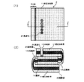
図5は、実施形態3の圧着シート3の圧着前の状態を説明する図である。
図5(1)は、圧着シート3を上面から見た図である。
図5(2)は、図5(1)のI−I矢視断面図である。
図6は、実施形態3の圧着シート3の圧着後の状態を説明する図である。
図6(1)は、圧着シート3を圧着後に貫通孔24より隠蔽面の一部が露出している部分(本実施形態3では、印刷部13)を左側にした時に上面から見た図である。
図6(2)は、図6(1)のJ−J矢視断面図である。
(Embodiment 3)
The third embodiment is a pressure-sensitive adhesive sheet according to the first or second embodiment, wherein a part of the surface that is folded and overlapped by the fold portion can be visually recognized after being crimped by the through-hole provided at a predetermined position of the base material. is there.
More specifically, when folded at the
The configuration of the third embodiment is different from the second embodiment in that two folds applied in the second embodiment are formed. Hereinafter, differences from the second embodiment will be described.
FIG. 5 is a diagram illustrating a state before the pressure-bonding sheet 3 according to Embodiment 3 is pressed.
FIG. 5A is a view of the pressure-bonding sheet 3 as viewed from above.
FIG. 5B is a cross-sectional view taken along the line I-I in FIG.
FIG. 6 is a diagram for explaining a state after the crimping of the crimping sheet 3 according to the third embodiment.
FIG. 6A is a view as seen from above when a part of the concealed surface exposed from the through hole 24 after the pressure-bonding sheet 3 is pressure-bonded (in the third embodiment, the printing portion 13) is on the left side. is there.
FIG. 6B is a cross-sectional view taken along the line JJ in FIG.
本実施形態3は、折部が谷折部21と山折部22との2箇所に形成されており、谷折部21では谷折り、山折部22では山折りで折り重ねた際に3紙面が折り重なる、いわゆるZ折と呼ばれる圧着シートである。さらに、貫通孔24を通して基材10もしくは感圧接着層11上に印刷された「郵便はがき」という文字が視認でき、郵便はがきとして利用できる圧着シートである。
図5は、本実施形態3に係わる圧着シート3の概略図の一例である。図5(1)において、実施形態2と異なる点は、圧着後に貫通孔24より隠蔽面の一部を露出させるようにした点である。即ち、本実施形態3では、印刷部13のある紙面と貫通孔24のある紙面の間に谷折部21が設けられているだけでなく、さらに印刷部13のある紙面と同サイズの紙面が山折部22に対称である位置に設けられている。
In the third embodiment, the folding part is formed at two places, the
FIG. 5 is an example of a schematic view of the pressure-bonding sheet 3 according to the third embodiment. 5 (1) is different from the second embodiment in that a part of the concealment surface is exposed from the through hole 24 after the pressure bonding. That is, in the third embodiment, not only the
図5(2)は、I−I矢視断面図を表している。裁断部20に沿って形成される圧縮部12a、12bは、谷折部21または山折部22で折り重ねた際に、圧縮部12a、12bが隠蔽される、つまり感圧接着層11と圧着される面に形成する。
また谷折部21で折り重ねた際に、貫通孔24を通して「郵便はがき」という文字が視認できる位置に、印刷部13を形成する。
FIG. 5B represents a cross-sectional view taken along the arrow I-I. The compression parts 12a and 12b formed along the cutting
Further, when folded at the
図6(1)は、圧着後の圧着シート3である。図6(2)は、J−J矢視断面図を表している。本実施形態3では、印刷後、ローラー等により裁断部20に沿って、表裏それぞれ圧縮部12a、12bが形成され、裁断部20にて裁断した後、谷折部21および山折部22で折り重ねて感圧接着層11同士を圧着する。
FIG. 6A shows the pressure-bonding sheet 3 after pressure bonding. FIG. 6B shows a cross-sectional view taken along the line JJ. In the third embodiment, after printing, compression parts 12a and 12b are formed along the cutting
(本実施形態3の作用効果)
以上のように本実施形態3によれば、実施形態2と同様の作用効果を奏すると共に、追加された構成により、次の作用効果を奏する。すなわち、圧着後の圧着シート1と圧着シート3が同サイズであれば、圧着シート3は、面積比で1.5倍の紙面を持ち、隠蔽部は2倍であるため、より多くの個人情報等を印刷し、隠蔽面に収めることができる。
(Operational effect of the third embodiment)
As described above, according to the third embodiment, the same operational effects as those of the second embodiment are exhibited, and the following operational effects are achieved by the added configuration. That is, if the pressure-
(実施形態4)
実施形態4は実施形態1または2において、折部で折られて重なる基材は、一端が短いことで重なる面の一部が圧着後に視認できることを特徴とするものである。
より具体的には、本実施形態4は、谷折部21で折り重ねた際に、裁断部20の一方(裁断部20a)が他方の裁断部20bと谷折部21に対して対称の位置ではないため、基材10もしくは感圧接着層11上に印刷された「郵便はがき」という文字が隠蔽されず視認でき、郵便はがきとして利用できる圧着シートである。
図7は、本実施形態4に係わる圧着シート4の概略図の一例である。図7(1)において、実施形態3と異なる点は、谷折部21に対して、裁断部20aと対称となる位置より谷折部21に近い位置で裁断部20bが形成されており、谷折部21で折り重ねた際に、「郵便はがき」という文字が視認できる位置に、印刷部13が形成されていることにある。
図7(2)は、図7(1)のG−G矢視断面図を表している。裁断部20aと裁断部20bは、谷折部21に対して非対称であり、谷折部21で折り重ねた際に、印刷部13を隠蔽しない位置で裁断部20aを形成する。
また、圧縮部12bは、裁断部20a上には形成せず、谷折部21に対して近い裁断部20aに沿って形成する。
(Embodiment 4)
The fourth embodiment is characterized in that, in the first or second embodiment, the base material that is folded and overlapped at the fold portion has a short one end so that a part of the overlapping surface can be visually recognized after pressure bonding.
More specifically, in Embodiment 4, when folded at the
FIG. 7 is an example of a schematic view of the pressure-bonding sheet 4 according to the fourth embodiment. 7 (1), the difference from Embodiment 3 is that the cut portion 20b is formed at a position closer to the
FIG. 7 (2) shows a cross-sectional view taken along the arrow GG in FIG. 7 (1). The cutting part 20a and the cutting part 20b are asymmetric with respect to the valley fold
Moreover, the compression part 12b is not formed on the cutting part 20a, but is formed along the cutting part 20a close to the valley fold
図8(1)は、圧着後の圧着シート4であり、印刷部13を左側に配置した際の状態を表している。図8(2)は、図8(1)のH−H矢視断面図を表している。
本実施形態4では、印刷後、ローラー等により裁断部20bに沿って圧縮部12bが形成され、裁断部20aおよび裁断部20bにて裁断した後、谷折部21で折り重ねて感圧接着層11同士を圧着する。
谷折部21に対して裁断部20a、裁断部20bは非対称であるから、一方の基材10は一端が短くなり、本実施形態4では、隠蔽面の一部である裁断部20a付近の感圧接着層11および印刷部13が露出する。
FIG. 8A shows the pressure-bonded sheet 4 after pressure bonding, and shows a state when the
In the fourth embodiment, after printing, the compressed portion 12b is formed along the cutting portion 20b by a roller or the like, and after cutting at the cutting portion 20a and the cutting portion 20b, the pressure-sensitive adhesive layer is folded at the
Since the cut portion 20a and the cut portion 20b are asymmetric with respect to the
圧着シート4は製造後、郵送等により受取人へ送付され、受取人が開封する際に、圧縮部12a、または圧縮部12bより剥離することで開封できる。圧縮部12a、12bによる感圧接着層11の接着力は、感圧接着層11の圧着面に多少の隙間があるか、もしくは圧縮部12a、12b以外の圧着面に比べて弱い接着力にて圧着されている。さらに、基材10が圧縮されることにより、圧縮部12の基材10に対する強度が上がる。そのため、裁断部20a、20bでの裁断面にキズや折れ等で基材10が破れ易くなっていても、剥離の際に基材10のキズや折れ等が広がることなく、感圧接着層11同士の接着面より剥がし、隠蔽された面の情報を閲覧することができる
After the manufacture, the pressure-bonding sheet 4 is sent to a recipient by mail or the like, and can be opened by being peeled off from the compression portion 12a or the compression portion 12b when the recipient opens. The adhesive force of the pressure-
(本実施形態4の作用効果)
以上のように本実施形態4によれば、隠蔽される感圧接着層11の面に対して、デザインや個人情報等になんら制約させることなく印刷をすることができ、糊殺し剤等を用いることなく、粘着シートの縁部に粘着剤の効力を弱める部分を形成することができる。さらに、郵便はがきとして送付できる。
(Operational effect of the fourth embodiment)
As described above, according to the fourth embodiment, the surface of the pressure-
加えて、基材10が圧縮された圧縮部12は、圧縮されていない基材10より強度が高くより破れにくいため、圧着シート4を受け取った人が圧縮部12よりめくり開く際に、亀裂やキズがあっても破れが広がることなく、粘着剤面をきれいに剥がすことができる。
なお、圧縮されている部分には、隙間を形成することもできる。
In addition, since the compressed portion 12 in which the base material 10 is compressed is stronger and more difficult to tear than the uncompressed base material 10, when the person who receives the pressure-bonding sheet 4 turns over from the compressed portion 12, cracks and Even if there is a scratch, the adhesive surface can be peeled off cleanly without spreading the tear.
A gap can also be formed in the compressed portion.
(製造方法の説明)
以下に、圧着シート2の製造方法のうち、貫通孔24の形成方法について説明する。
貫通孔24の形成方法は、マージナルパンチ23と同様に円形の刃型で良いが、貫通孔の大きさ、数及び貫通孔同士の間隔は、印刷部13の文字などの大きさ、文字数、文字同士の間隔に合わせて、基材10を谷折部21で折り重ねて、その印刷部13が貫通孔24を通して認識できるようにするため、レーザー照射にて形成することが望ましい。
(Description of manufacturing method)
Below, the formation method of the through-hole 24 among the manufacturing methods of the crimping | compression-
The formation method of the through hole 24 may be a circular blade shape like the marginal punch 23, but the size and number of the through holes and the interval between the through holes are the size of the characters, the number of characters, the characters of the
(レーザー照射による切削加工)
レーザー照射手段としては、レーザー光として、YAGレーザー、炭酸ガスレーザー、ルビーレーザーなどを用い、特にYAGレーザーは、波長が短く、微小なスポットに集光できるため、より微細な加工が可能であり、好ましく用いられる。レーザー照射手段により、任意の形状、大きさで、対象物を切削して、貫通孔の形成、コーナーカット部の形成をすることができる。
(Cutting by laser irradiation)
As the laser irradiation means, YAG laser, carbon dioxide laser, ruby laser, etc. are used as laser light, and in particular, YAG laser has a short wavelength and can be focused on a minute spot, so finer processing is possible. Preferably used. A laser irradiation means can cut an object with an arbitrary shape and size to form a through hole and a corner cut portion.
本実施形態で適用するレーザー照射手段の例を説明すると、まずレンズによりレーザー光を集光して、印刷物に基材の面へ照射する。その際に、レーザー光の照射条件(ビーム径、パワー、走査速度等)を調整することにより、貫通孔、コーナーカット部の加工する大きさを制御でき、また貫通孔の周辺の感圧接着剤、コーナーカット部の周辺の感圧接着剤の熱劣化する領域の大きさも調整することができる。このように、本発明ではレーザー照射を行なうことで、簡単に、精度が高く、再現性良く、圧着シートと非接触で、加工ができる。 An example of the laser irradiation means applied in the present embodiment will be described. First, laser light is condensed by a lens, and the printed material is irradiated onto the surface of the substrate. At that time, by adjusting the laser light irradiation conditions (beam diameter, power, scanning speed, etc.), the processing size of the through hole and the corner cut portion can be controlled, and the pressure sensitive adhesive around the through hole. The size of the heat-degraded region of the pressure-sensitive adhesive around the corner cut portion can also be adjusted. As described above, in the present invention, by performing laser irradiation, processing can be easily performed with high accuracy, good reproducibility, and without contact with the pressure-bonding sheet.
本実施形態のレーザー照射手段は、約0.9〜11μmの赤外線領域のレーザー光線を使用することが好ましく、レーザー光を照射された部分は、加熱されることになる。レーザー光を照射された部分は、局所的に加熱され、その部分の融点を越えた状態の液相時に、その部分を吹き飛ばすことにより切削される。 The laser irradiation means of this embodiment preferably uses a laser beam in an infrared region of about 0.9 to 11 μm, and the portion irradiated with the laser light is heated. The portion irradiated with the laser light is locally heated and cut by blowing off the portion in the liquid phase in a state exceeding the melting point of the portion.
次に、圧縮部12を形成する方法について、説明する。
図10は、本実施形態2の圧着シート2の圧縮部12を形成する一例である。図10において、基材10は連続シートとなっており、基材10上に、感圧接着層11、印刷部(図示なし)、裁断部20等が形成された後に、感圧接着層11の一方の面にある裁断部20に沿って連続シートの動きに合わせてローラー30を回転させながら押し当てて、基材10および感圧接着層11を圧縮し、圧縮部12aを形成する。
Next, a method for forming the compression unit 12 will be described.
FIG. 10 is an example of forming the compression section 12 of the pressure-
連続シートはその後、表裏返し部31にて、基材10の表裏を返した後、他方の面にある他方の裁断部20に沿ってローラー30にて押し当てて、基材10および感圧接着層11を圧縮し、圧縮部12bを形成する。圧縮した際に、略凹部が形成されるが、圧縮前と比べて50〜400μm程度、好ましくは200μm程度の窪みになるよう圧縮力を設定する。
Thereafter, the continuous sheet is turned upside down at the front and back turning
(変形例1)
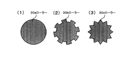
実施形態1〜3において圧縮部12を形成するためのローラー30は、円盤状の形状をしており、押し面が一定な曲面であったが、円周の一定間隔で押し面や押し部を設けた歯車形や星形にしてもよい。
図11は、圧縮部12を形成するためローラーを説明する他の例である。
図11(1)は、実施形態1で用いたローラーを回転方向横より見た図である。
図11(2)は、円周の一定間隔で押し面を設けた歯車形をしたローラーを説明する図である。
図11(3)は、円周の一定間隔で押し部を設けた星形をしたローラーを説明する図である。
(Modification 1)
In the first to third embodiments, the roller 30 for forming the compression portion 12 has a disk shape and the pressing surface is a constant curved surface. However, the pressing surface and the pressing portion are arranged at regular intervals around the circumference. The provided gear shape or star shape may be used.
FIG. 11 is another example illustrating a roller for forming the compression unit 12.
FIG. 11A is a view of the roller used in
FIG. 11 (2) is a diagram for explaining a gear-shaped roller provided with a pressing surface at regular intervals around the circumference.
FIG. 11 (3) is a diagram for explaining a star-shaped roller provided with pushing portions at regular intervals around the circumference.
この場合、図11(1)の様に、円盤状である形状のローラーを用いると、圧縮部12はローラー30aが通過すると基材10に略凹状の窪みが形成される。 In this case, as shown in FIG. 11 (1), when a roller having a disk shape is used, a substantially concave recess is formed in the base material 10 when the roller 30 a passes through the compression unit 12.
また、図11(2)の様に、円周の一定間隔で押し面を設け、一定間隔で窪み(押し面が抜けた部分)を設けた歯車形をしたローラーを用いると、圧縮部12はローラー30bが通過すると略凹状の窪みと窪みのない、または略凹状の浅い窪みが交互に形成される。 Further, as shown in FIG. 11 (2), when a roller having a gear shape in which a pressing surface is provided at regular intervals around the circumference and depressions (parts where the pressing surface is removed) is provided at regular intervals, the compression unit 12 is When the roller 30b passes, a substantially concave depression and a shallow depression having no depression or a substantially concave depression are alternately formed.
またさらに、図11(3)の様に、円周の一定間隔で押し部を設け、一定間隔で溝部を設けた星形をしたローラーを用いると、圧縮部12はローラー30cが通過すると略凹状の窪みと窪みのない、または略凹状の浅い窪みが交互に形成される。ローラー30cを用いることで、ローラー30bと比べ、より略凹状の窪みと窪みの間隔を狭くした圧縮部を形成することができる。 Furthermore, as shown in FIG. 11 (3), when a star-shaped roller provided with pushing portions at regular intervals around the circumference and grooves at regular intervals is used, the compression unit 12 is substantially concave when the roller 30c passes. And shallow depressions without or substantially concave are formed alternately. By using the roller 30c, compared with the roller 30b, the compression part which narrowed the space | interval of a more substantially concave shape and a hollow can be formed.
(変形例1の作用効果)
実施形態1〜3と同様の作用効果を奏すると共に、追加された機能により、次の作用効果を奏する。すなわち、円周の一定間隔で押し面や押し部を設けた歯車形や星形をしたローラーを用いることで、略凹状の窪みと窪みのない、または略凹状の浅い窪みが交互に形成され、窪みのある部分は、感圧接着層11同士が重なり圧着される際に、窪みのない部分の圧着力に比べ弱く圧着されるため、圧着力の強い部分と弱い部分が交互に現れ、圧縮部12に対する圧着力の調整が可能である。
(Operational effect of modification 1)
While exhibiting the same operation effect as Embodiments 1-3, the following operation effect is produced by the added function. That is, by using a gear-shaped or star-shaped roller provided with a pressing surface or a pressing portion at regular intervals around the circumference, substantially concave depressions and no depressions, or substantially concave shallow depressions are alternately formed, When the pressure-sensitive adhesive layers 11 are overlapped and pressure-bonded, the portion with the depression is weakly bonded as compared with the pressure-bonding force of the portion without the depression. Therefore, the strong and weak portions appear alternately, and the compression portion It is possible to adjust the pressing force with respect to 12.
(変形例2)
実施形態1〜3において圧縮部12を形成するためローラーを用いていたが、押し型でもよい。
図12は、圧縮部を形成するため押し型を説明する一例である。
この場合、図12の押し型を用いることで、図11(2)の一定間隔で押し面を設けた歯車形をしたローラー30bを用いた場合と同様の略凹状の窪みと窪みのない、または略凹状の浅い窪みが交互に形成される。
(Modification 2)
Although the roller was used in order to form the compression part 12 in Embodiment 1-3, a pressing die may be used.
FIG. 12 is an example illustrating a pressing die for forming a compression portion.
In this case, by using the pressing mold of FIG. 12, there is no substantially concave dent and dent similar to the case of using the gear-shaped roller 30b provided with the pressing surface at regular intervals in FIG. 11 (2), or Substantially concave shallow depressions are alternately formed.
図12は、変形例2の圧着シートの圧縮部を形成するための押し型の一例である。図9または図10にあるローラー30を本押し型に置き換えることにより、基材10上に、感圧接着層11、印刷部(図示なし)、裁断部20等が形成された後に、感圧接着層11の面に対して一定間隔にて本押し型で押し当てて、基材10および感圧接着層11を圧縮する。
圧縮した際に、略凹部が形成されるが、圧縮前と比べて50〜400μm程度、好ましくは200μm程度の窪みになるよう圧縮力を設定する。なお、本押し型の押し当てる間隔は、基材の進行方向に対する速度から求めて、前回の押し跡と次の押し跡がほとんど重ならないことが望ましく、これにより作業効率が高くなる。
FIG. 12 is an example of a pressing die for forming the compression part of the pressure-bonding sheet of
When compressed, a substantially concave portion is formed, but the compression force is set so as to be a depression of about 50 to 400 μm, preferably about 200 μm, compared to before compression. It should be noted that the pressing interval of the main pressing die is determined from the speed in the traveling direction of the base material, and it is desirable that the previous pressing mark and the next pressing mark hardly overlap each other, thereby improving work efficiency.
(変形例2の作用効果)
実施形態1〜3と同様の作用効果を奏すると共に、追加された機能により、次の作用効果を奏する。すなわち、押し型の押し部の形状は、平面だけでなく、様々な形状の歯型で良いので、圧着性を考慮した一定間隔で押し面を設けた形状だけでなく、意匠性を考慮した模様状の形状でもよく、さまざまな形状を用いることができる。
(Operational effect of modification 2)
While exhibiting the same operation effect as Embodiments 1-3, the following operation effect is produced by the added function. In other words, the shape of the pressing portion of the pressing die is not limited to a flat surface, but may be a tooth shape having various shapes. Various shapes can be used.
(変形例3)
実施形態1〜3において圧着シートの圧縮部12は、裁断部20に沿って形成されているが、コーナー部25に形成してもよい。
コーナー部25は、製造後の圧着シートで、外縁部の角となるコーナー部の一部に、圧着シートをめくり開く際のきっかけとなる開封開始を示す部分である。前記コーナー部25は、圧着シートを受け取った人が圧着シートを容易にめくり開くことができるように、粘着シートのコーナー部の粘着剤の効力を弱める部分である。
(Modification 3)
In the first to third embodiments, the compression portion 12 of the pressure-bonding sheet is formed along the cutting
The corner portion 25 is a post-manufactured pressure-sensitive adhesive sheet, and is a portion that indicates the start of opening as a trigger when the pressure-sensitive adhesive sheet is turned over at a part of the corner portion that becomes the corner of the outer edge portion. The corner portion 25 is a portion that weakens the effectiveness of the adhesive at the corner portion of the pressure-sensitive adhesive sheet so that a person who receives the pressure-bonded sheet can easily open the pressure-bonded sheet.
図13は、コーナー部25に圧縮部12を形成する一例である。図13は、圧着シート1〜4において、基材10の一部を示しており、波線より右側を省略している。
裁断部20の端部に、少なくとも1つのコーナー部25を設ける。圧着シートを受け取った人が、めくり開始位置が分かるように、開封開始を示すような印刷を施しておくとよい。
コーナー部25の形成には、図9や図10に示したローラー30を用いて、裁断部20に沿って圧縮部12を形成した後、コーナー部25の略三角形部分を押し型で形成する。また、変形例2(図12参照)に示した押し型を用いて、圧縮部12を一度に形成してもよい。
FIG. 13 is an example in which the compression part 12 is formed in the corner part 25. FIG. 13 shows a part of the substrate 10 in the pressure-
At least one corner portion 25 is provided at the end of the cutting
For forming the corner portion 25, the compression portion 12 is formed along the cutting
(変形例3の作用効果)
実施形態1〜4と同様の作用効果を奏すると共に、追加された機能により、次の作用効果を奏する。すなわち、コーナー部25に圧縮部12を形成することにより、圧着シートを受け取った人が圧着シートのコーナー部よりめくり開く際に、粘着剤の効力が弱いコーナー部25からめくり開くことができ、粘着剤面をきれいに剥がすことができる。
(Operational effect of modification 3)
While exhibiting the same operation effect as Embodiments 1-4, there is the following operation effect by the added function. That is, by forming the compression portion 12 in the corner portion 25, when the person who receives the pressure-bonding sheet turns off from the corner portion of the pressure-bonding sheet, the pressure-sensitive adhesive can be turned off from the corner portion 25 where the adhesive is weak. The surface of the agent can be removed cleanly.
(変形例4)
実施形態1〜3において圧着シートの圧縮部12は、裁断部20に沿って形成されているが、コーナーカット部26に形成してもよい。
コーナーカット部26は、製造後の圧着シートにおいて、外縁部の角となるコーナー部の一部に設けた切り欠けである。圧着シートを受け取った人が圧着シートを容易にめくり開くことが開始できるように、粘着シートのコーナー部の粘着剤の効力を弱める部分である。
(Modification 4)
In the first to third embodiments, the compression portion 12 of the pressure-bonding sheet is formed along the cutting
The corner cut part 26 is a notch provided in a part of the corner part which becomes the corner of the outer edge part in the crimped sheet after manufacture. This is a part that weakens the effectiveness of the adhesive at the corner of the pressure-sensitive adhesive sheet so that a person who receives the pressure-sensitive adhesive sheet can easily start turning over the pressure-sensitive adhesive sheet.
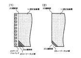
図14は、コーナーカット部に圧縮部を形成する一例である。図14(1)は、コーナーカット部26に圧縮部12を形成した状態を示し、図14(2)は、裁断部20および裁断部20cにて裁断後の状態を示す。図14は、圧着シート1〜4において、基材10の一部を示しており、波線より右側を省略している。
裁断部20の端部に、少なくとも1つのコーナーカット部26を設ける。圧着シートを受け取った人が、めくり開始位置が分かるように、開封開始を示すような印刷を施しておくとよい。
FIG. 14 is an example of forming a compression part in a corner cut part. FIG. 14 (1) shows a state where the compression part 12 is formed in the corner cut part 26, and FIG. 14 (2) shows a state after cutting by the cutting
At least one corner cut part 26 is provided at the end of the cutting
コーナーカット部26の形成には、図9や図10に示したローラー30を用いて、裁断部20に沿って圧縮部12を形成した後、裁断部20cを含めてコーナーカット部26の略三角形部分に押し型を押し当てて、コーナーカット部26部分の圧縮部12を形成する。また、変形例2(図1612参照)に示した押し型を用いて、圧縮部12を一度に形成してもよい。
後に、裁断部20および切り欠けを形成するための裁断部20cに沿って裁断し、折部(21、22)により折り重ねて感圧接着層11同士を圧着する。
裁断部20cは、直線に裁断するが、圧着シートを受け取った人がめくり開く際に、裁断部20cが直線であることで指にキズを負うことがあるため、裁断部20cを波型で裁断できると尚良い。
For forming the corner cut portion 26, the roller 30 shown in FIGS. 9 and 10 is used to form the compression portion 12 along the
Later, it cuts along the cutting
The cutting
(変形例4の作用効果)
実施形態1〜4と同様の作用効果を奏すると共に、追加された機能により、次の作用効果を奏する。すなわち、コーナー部25に圧縮部12を形成することにより、圧着シートを受け取った人が圧着シートのコーナーカット部よりめくり開く際に、粘着剤の効力が弱いコーナーカット部からめくり開くことができ、粘着剤面をきれいに剥がすことができる。
(Operational effect of modification 4)
While exhibiting the same operation effect as Embodiments 1-4, there is the following operation effect by the added function. That is, by forming the compression part 12 in the corner part 25, when the person who receives the pressure-bonding sheet turns off from the corner cut part of the pressure-bonding sheet, it can be turned off from the corner cut part where the effect of the adhesive is weak, The adhesive surface can be removed cleanly.
10 基材
11 感圧接着層
12,12a,12b 圧縮部
13 印刷部
20,20a,20b,20c 裁断部
21 谷折部
22 山折部
24 貫通孔
25 コーナー部
26 コーナーカット部
DESCRIPTION OF SYMBOLS 10
Claims (5)
前記一方の基材の表出面側であって、前記表出面を含み前記他方の基材の一辺を跨ぐ領域の基材および感圧接着層が圧縮されていることを特徴とする圧着シート。 A pressure-sensitive adhesive layer is provided on one surface of the base material, and the base material is a base material that is folded at one fold with the pressure-sensitive adhesive layer inside, and one base material is the other base material. Has an exposed surface extending from one side of the
A pressure-sensitive adhesive sheet, wherein a base material and a pressure-sensitive adhesive layer in a region on the exposed surface side of the one base material and including the exposed surface and straddling one side of the other base material are compressed.
前記中央に位置する基材の表出面側であって、前記表出面を含み前記両端に位置するそれぞれの基材の一辺を跨ぐ領域の基材および感圧接着層が圧縮されていることを特徴とする圧着シート。 A pressure-sensitive adhesive layer is provided on both surfaces of the base material, and the base material is divided on the basis of the fold portion folded in a Z shape at two fold portions with the pressure-sensitive adhesive layer inside. Of the materials, the base material located in the center has an exposed surface extending from one side of each base material located at both ends,
The base material and the pressure-sensitive adhesive layer are compressed on the exposed surface side of the base material located at the center and straddling one side of each base material including the exposed surface and located at both ends. A crimping sheet.
5. The pressure-bonded sheet is provided with a corner portion or a corner cut portion, and a base material and a pressure-sensitive adhesive layer located at the corner portion or the corner cut portion are compressed. The crimping sheet according to one item.
Priority Applications (1)
| Application Number | Priority Date | Filing Date | Title |
|---|---|---|---|
| JP2016060693A JP2017170802A (en) | 2016-03-24 | 2016-03-24 | Press-bonded sheet |
Applications Claiming Priority (1)
| Application Number | Priority Date | Filing Date | Title |
|---|---|---|---|
| JP2016060693A JP2017170802A (en) | 2016-03-24 | 2016-03-24 | Press-bonded sheet |
Publications (1)
| Publication Number | Publication Date |
|---|---|
| JP2017170802A true JP2017170802A (en) | 2017-09-28 |
Family
ID=59972739
Family Applications (1)
| Application Number | Title | Priority Date | Filing Date |
|---|---|---|---|
| JP2016060693A Pending JP2017170802A (en) | 2016-03-24 | 2016-03-24 | Press-bonded sheet |
Country Status (1)
| Country | Link |
|---|---|
| JP (1) | JP2017170802A (en) |
Cited By (1)
| Publication number | Priority date | Publication date | Assignee | Title |
|---|---|---|---|---|
| WO2019049801A1 (en) | 2017-09-06 | 2019-03-14 | 曙ブレーキ工業株式会社 | Caliper for opposed piston-type disc brake |
-
2016
- 2016-03-24 JP JP2016060693A patent/JP2017170802A/en active Pending
Cited By (1)
| Publication number | Priority date | Publication date | Assignee | Title |
|---|---|---|---|---|
| WO2019049801A1 (en) | 2017-09-06 | 2019-03-14 | 曙ブレーキ工業株式会社 | Caliper for opposed piston-type disc brake |
Similar Documents
| Publication | Publication Date | Title |
|---|---|---|
| JPH0229317A (en) | Joining device for two layer or more of paper product | |
| JP2017170802A (en) | Press-bonded sheet | |
| JP5830995B2 (en) | Manufacturing method of crimped sheet | |
| JP6701684B2 (en) | Crimping sheet | |
| JP5994894B2 (en) | Removable pressure-bonding sheet | |
| JP5954466B2 (en) | Crimp sheet | |
| JP5830994B2 (en) | Manufacturing method of crimped sheet | |
| JP4121027B2 (en) | Label paper and its processing method | |
| JPH05116489A (en) | Stacking sheet and method of making the same | |
| JP5772281B2 (en) | Manufacturing method of crimped sheet | |
| JP5772282B2 (en) | Crimping sheet and manufacturing method thereof | |
| JP3634065B2 (en) | Continuous paper processing equipment | |
| EP2496424B1 (en) | One-piece mailing document | |
| JP4368278B2 (en) | Information forming sheet | |
| JPH1128879A5 (en) | ||
| JP2007210181A (en) | Concealing postcard | |
| JP2001121854A (en) | Sheet for information hiding body and pressure-bonded postal card thereby | |
| JP3645355B2 (en) | Continuous paper processing equipment | |
| JP2004068232A (en) | Information recording paper and its manufacturing method | |
| JP2005272623A (en) | Paper | |
| JPH0967063A (en) | Continuous paper processing device | |
| JP2017145340A (en) | Production method of superposed adhesive sheet | |
| JP3975372B2 (en) | Wrap carton | |
| JPH09290452A (en) | Method of manufacturing laminated sheet for easy peeling | |
| JP2887342B2 (en) | Method for producing crimped postcard and folding machine used for it |