JP2017172902A - Gas water heater - Google Patents
Gas water heater Download PDFInfo
- Publication number
- JP2017172902A JP2017172902A JP2016060863A JP2016060863A JP2017172902A JP 2017172902 A JP2017172902 A JP 2017172902A JP 2016060863 A JP2016060863 A JP 2016060863A JP 2016060863 A JP2016060863 A JP 2016060863A JP 2017172902 A JP2017172902 A JP 2017172902A
- Authority
- JP
- Japan
- Prior art keywords
- water
- heat exchanger
- case
- plate
- heat exchange
- Prior art date
- Legal status (The legal status is an assumption and is not a legal conclusion. Google has not performed a legal analysis and makes no representation as to the accuracy of the status listed.)
- Granted
Links
Images


Classifications
-
- Y—GENERAL TAGGING OF NEW TECHNOLOGICAL DEVELOPMENTS; GENERAL TAGGING OF CROSS-SECTIONAL TECHNOLOGIES SPANNING OVER SEVERAL SECTIONS OF THE IPC; TECHNICAL SUBJECTS COVERED BY FORMER USPC CROSS-REFERENCE ART COLLECTIONS [XRACs] AND DIGESTS
- Y02—TECHNOLOGIES OR APPLICATIONS FOR MITIGATION OR ADAPTATION AGAINST CLIMATE CHANGE
- Y02B—CLIMATE CHANGE MITIGATION TECHNOLOGIES RELATED TO BUILDINGS, e.g. HOUSING, HOUSE APPLIANCES OR RELATED END-USER APPLICATIONS
- Y02B30/00—Energy efficient heating, ventilation or air conditioning [HVAC]
Landscapes
- Details Of Fluid Heaters (AREA)
Abstract
【課題】強度の高い2次熱交換器を有するガス給湯器を提供すること【解決手段】バーナーの直上に配置された1次熱交換器と、この1次熱交換器を通過した燃焼ガスが流される2次熱交換器(12)と、を有し、バーナーにおいて発生した燃焼ガスによって、1次熱交換器及び2次熱交換器(12)を流される水が温められるガス給湯器において、2次熱交換器(12)は、筒状のケース(17)と、このケース(17)の両端部をそれぞれ塞ぐエンドプレート(41〜44,51〜54)と、これらのエンドプレート(41〜44,51〜54によって両端が支持され内部に燃焼ガスが流される複数の熱交換チューブ(31〜34)と、これらの熱交換チューブ(31〜34)の内部に配置されたフィンと、からなる。【選択図】図2A gas water heater having a secondary heat exchanger with high strength is provided. A primary heat exchanger disposed immediately above a burner and a combustion gas passing through the primary heat exchanger are provided. A gas water heater in which water flowing through the primary heat exchanger and the secondary heat exchanger (12) is heated by the combustion gas generated in the burner. The secondary heat exchanger (12) includes a cylindrical case (17), end plates (41 to 44, 51 to 54) that respectively close both ends of the case (17), and end plates (41 to 41). The heat exchange tubes (31 to 34), both ends of which are supported by 44, 51 to 54 and in which the combustion gas flows, and fins disposed inside these heat exchange tubes (31 to 34), [Selection] Figure 2
Description
本発明は、2つの熱交換器を有するガス給湯器に関する。 The present invention relates to a gas water heater having two heat exchangers.
家庭等で用いられる給湯器として、バーナーにおいて発生した燃焼ガスの熱により水を温めるガス給湯器が知られている。ガス給湯器には、バーナーの直上に配置された1次熱交換器と、この1次熱交換器を通過した燃焼ガスが流される2次熱交換器と、を有するものが存する。ガス給湯器に設けられた2次熱交換器に関する従来技術として特許文献1に開示された技術がある。 2. Description of the Related Art As a water heater used at home and the like, a gas water heater that warms water by the heat of combustion gas generated in a burner is known. Some gas water heaters include a primary heat exchanger disposed immediately above a burner and a secondary heat exchanger through which combustion gas that has passed through the primary heat exchanger flows. There is a technique disclosed in Patent Document 1 as a conventional technique related to a secondary heat exchanger provided in a gas water heater.
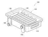
図10を参照する。図10は、特許文献1の図2(c)を再掲したものである。2次熱交換器100は、対向する側壁にガス導入孔110及びガス排出孔120とが形成されたケース130(開放されているケース130の上部は別の部材で覆われる)と、このケース130内に配置され内部を水が流れる管140と、ケース130の外側に設けられ管140の導入口と接続する水導入部150と、ケース130の外側に設けられ管140の排出口と接続する水排出部160と、からなる。
Please refer to FIG. FIG. 10 is a reproduction of FIG. 2C of Patent Document 1. The
燃焼ガスは、ガス導入孔110からケース130内に流れ込む。一方、水は、水導入部150からケース130内に配置された管140の内部に流れこむ。ケース130内において、燃焼ガスの熱は、管140を介して水に伝わる。温められた水は、水排出部160から排出され、燃焼ガスは、ガス排出孔120から排出される。
The combustion gas flows into the
ところで、通常の使用時において、給湯器の使用者は、給水と止水とを繰り返す。このとき、いわゆるウォーターハンマー現象が生ずることもあり、2次熱交換器の管には、大きな負荷が加わる。このため、2次熱交換器の管には、このような負荷に耐える程度の強度が必要となる。 By the way, during normal use, the user of the water heater repeats water supply and water stoppage. At this time, a so-called water hammer phenomenon may occur, and a large load is applied to the pipe of the secondary heat exchanger. For this reason, the pipe | tube of a secondary heat exchanger requires the intensity | strength of the grade which can endure such a load.
本発明は、強度の高い2次熱交換器を有するガス給湯器の提供を課題とする。 This invention makes it a subject to provide the gas water heater which has a secondary heat exchanger with high intensity | strength.
請求項1による発明によれば、バーナーの直上に配置された1次熱交換器と、この1次熱交換器を通過した燃焼ガスが流される2次熱交換器と、を有し、前記バーナーにおいて発生した燃焼ガスによって、前記1次熱交換器及び前記2次熱交換器を流される水が温められるガス給湯器において、
前記2次熱交換器は、筒状のケースと、このケースの両端部をそれぞれ塞ぐエンドプレートと、これらのエンドプレートによって両端が支持され内部に前記燃焼ガスが流される複数の熱交換チューブと、これらの熱交換チューブの内部に配置されたフィンと、からなることを特徴とするガス給湯器が提供される。
According to the first aspect of the present invention, the burner has a primary heat exchanger disposed immediately above the burner, and a secondary heat exchanger through which the combustion gas that has passed through the primary heat exchanger flows. In the gas water heater in which the water flowing through the primary heat exchanger and the secondary heat exchanger is heated by the combustion gas generated in
The secondary heat exchanger includes a cylindrical case, end plates that close both ends of the case, a plurality of heat exchange tubes that are supported at both ends by the end plates and into which the combustion gas flows, There is provided a gas water heater characterized by comprising fins arranged inside these heat exchange tubes.
請求項2に記載のごとく、好ましくは、前記ケースの内部は、前記水の流れ方向を規制する水路規制体によって複数の部屋に区画され、
前記熱交換チューブの一部は、前記水路規制体によって支持されている。
As described in claim 2, preferably, the inside of the case is partitioned into a plurality of rooms by a water channel regulating body that regulates the flow direction of the water,
A part of the heat exchange tube is supported by the water channel regulator.
請求項3に記載のごとく、好ましくは、前記水路規制体は、前記ケースの内部を仕切る仕切板と、前記ケースの内部を仕切ると共に前記水が通過可能なゲート板と、からなり、
前記ゲート板には、前記水が通過する通過部が形成され、前記水の流れ方向で互いに隣接する前記通過部は、前記ケースの底部からの高さが異なる。
As described in claim 3, preferably, the water channel regulating body includes a partition plate that partitions the inside of the case, and a gate plate that partitions the inside of the case and allows the water to pass through,
The gate plate is formed with a passage through which the water passes, and the passages adjacent to each other in the water flow direction have different heights from the bottom of the case.
請求項4に記載のごとく、好ましくは、前記水路規制体は、前記ケースのなかの略対向する部位、又は、エンドプレートのなかの略対向する部位に当接している。 According to a fourth aspect of the present invention, preferably, the water channel restricting body is in contact with a substantially opposed portion of the case or a substantially opposed portion of the end plate.
請求項1に係る発明では、2次熱交換器は、筒状のケースと、エンドプレートと、燃焼ガスが流される複数の熱交換チューブと、これらの熱交換チューブの内部に配置されたフィンと、からなる。即ち、水はケースとエンドプレートとにより囲まれる領域内を流れ、燃焼ガスは熱交換チューブの内部を流れる。このため、熱交換チューブには、内側に向かって潰れるように水圧が加わる。ここで、熱交換チューブは、内部からフィンにより支持されている。フィンは、熱交換チューブを潰す方向に加わる力に抗する作用を有する。これにより、熱交換チューブが水圧により潰されることを抑制できる。このような強度の高い熱交換チューブを用いることにより、強度の高い2次熱交換器を提供することができる。また、熱交換チューブの内部に配置されたフィンにより、燃焼ガスの熱をより多く回収し、水へと伝えることができる。 In the invention according to claim 1, the secondary heat exchanger includes a cylindrical case, an end plate, a plurality of heat exchange tubes through which combustion gas flows, fins disposed inside these heat exchange tubes, It consists of. That is, water flows in the region surrounded by the case and the end plate, and the combustion gas flows in the heat exchange tube. For this reason, a water pressure is applied to the heat exchange tube so as to be crushed inward. Here, the heat exchange tube is supported by fins from the inside. A fin has the effect | action resisting the force added to the direction which crushes a heat exchange tube. Thereby, it can suppress that a heat exchange tube is crushed by water pressure. By using such a high-strength heat exchange tube, a high-strength secondary heat exchanger can be provided. Further, more heat of the combustion gas can be recovered and transferred to water by the fins arranged inside the heat exchange tube.
請求項2に係る発明では、ケースの内部は、水の流れ方向を規制する水路規制体によって複数の部屋に区画されている。即ち、ケースの内部において、水は、一の部屋から隣接する部屋へ流れるよう規制されている。水が、水の導入口から水の排出口に向かって直接的に流れることを抑制できる。水の流路を長くすることができるため、より多くの熱エネルギを回収することができる。 In the invention which concerns on Claim 2, the inside of the case is divided into the some room by the water-path regulation body which regulates the flow direction of water. In other words, water is restricted from flowing from one room to an adjacent room inside the case. Water can be prevented from flowing directly from the water inlet to the water outlet. Since the water flow path can be lengthened, more heat energy can be recovered.
加えて、熱交換チューブの一部は、水路規制体によって支持されている。熱交換チューブは、両端がエンドプレートに支持されると共に、水路規制体にも支持される。そのため、熱交換チューブの強度は高くなる。 In addition, a part of the heat exchange tube is supported by the water channel regulating body. Both ends of the heat exchange tube are supported by the end plate and are also supported by the water channel regulating body. Therefore, the strength of the heat exchange tube is increased.
請求項3に係る発明では、水路規制体は、ケースの内部を仕切る仕切板と、ケースの内部を仕切ると共に水が通過可能なゲート板と、からなり、ゲート板には、水が通過する通過部が形成され、水の流れ方向で互いに隣接する通過部は、ケースの底部からの高さが異なる。即ち、水路規制体は、板を組み合わせて構成される。そのため、ケース内において、熱交換チューブが配置されるスペースを圧迫せずに、水路規制体を設けることができる。 In the invention according to claim 3, the water channel regulating body includes a partition plate that partitions the inside of the case, and a gate plate that partitions the inside of the case and allows water to pass therethrough. The passages adjacent to each other in the water flow direction have different heights from the bottom of the case. That is, the water channel regulating body is configured by combining plates. Therefore, the water channel regulating body can be provided in the case without pressing the space where the heat exchange tube is arranged.
加えて、ゲート板に形成され互いに隣接する通過部は、ケースの底部からの高さが異なる。そのため、ゲート板により挟まれたそれぞれ部屋において、水はケースの底部に対して斜めに流れる。水は、ケース内を蛇行して流れるため、水の流路は長くなる。結果、より多くの熱エネルギを回収することができる。 In addition, the passage portions formed on the gate plate and adjacent to each other have different heights from the bottom portion of the case. Therefore, in each room sandwiched between the gate plates, water flows obliquely with respect to the bottom of the case. Since water flows in a meandering manner in the case, the flow path of water becomes long. As a result, more heat energy can be recovered.
請求項4に係る発明では、水路規制体は、ケースのなかの略対向する部位、又は、エンドプレートのなかの略対向する部位に、当接又は接合している。即ち、ケースとエンドプレートとからなる筐体は、水路規制体により内部から支持される。そのため、筐体の強度は高くなる。水路規制体が接合された場合、筐体の内部を流れる水の水圧に耐えやすくなる。 In the invention which concerns on Claim 4, the water path control body is contact | abutted or joined to the site | part which opposes substantially in a case or the site | part which opposes substantially in an end plate. In other words, the casing composed of the case and the end plate is supported from the inside by the water channel regulating body. For this reason, the strength of the casing is increased. When the water channel regulator is joined, it becomes easy to withstand the water pressure of the water flowing inside the housing.
本発明の実施の形態を添付図に基づいて以下に説明する。なお、Inは、2次熱交換器に燃焼ガスが導入される側、Ouは2次熱交換器から燃焼ガスが排出される側を示している。
<実施例1>
Embodiments of the present invention will be described below with reference to the accompanying drawings. Note that In represents a side where combustion gas is introduced into the secondary heat exchanger, and Ou represents a side where combustion gas is discharged from the secondary heat exchanger.
<Example 1>
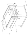
図1を参照する。図1には、本発明によるガス給湯器の内部に設けられる熱交換器10が示されている。この熱交換器10は、バーナーの直上に配置される1次熱交換器11と、この1次熱交換器11に載せられ1次熱交換器11を通過した燃焼ガスが流される2次熱交換器12と、からなる。バーナーにおいて発生した燃焼ガスにより、1次熱交換器11及び2次熱交換器12を流される水が温められる。以下、2次熱交換器12の詳細について説明する。
Please refer to FIG. FIG. 1 shows a
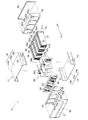
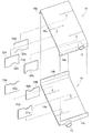
図2を併せて参照する。2次熱交換器12は、水導入部13を有する下側ケース半体14に水排出部15を有する上側ケース半体16が重ね合わされてなる筒状のケース17と、このケース17内に設けられ水の流れ方向を規制する水路規制板20(水路規制体20)と、この水路規制板20に嵌合し燃焼ガスが流される第1〜第4の熱交換チューブ31〜34と、これら第1〜第4の熱交換チューブ31〜34の燃焼ガスが導入される側の端部31a〜34aに設けられる第1〜第4の導入側エンドプレート41〜44と、これらの第1〜第4の導入側エンドプレート41〜44を連結させる導入側連結プレート45と、導入側連結プレート45を覆う導入側蓋体46と、第1〜第4の熱交換チューブ31〜34の燃焼ガスが排出される側の端部31b〜34bに設けられる第1〜第4の排出側エンドプレート51〜54と、これらの第1〜第4の排出側エンドプレート51〜54を連結させる排出側連結プレート55と、この排出側連結プレート55を覆う排出側蓋体56と、からなる。
Please refer to FIG. The
下側ケース半体14は、矩形形状の板材の両端が折り曲げられて形成され、底部14aと、この底部14aの両端から上方に延びる下側側壁部14b,14bと、からなる。上側ケース半体16は、矩形形状の板材の両端が折り曲げられて形成され、天井部16aとこの天井部16aの両端から下方に延びる上側側壁部16b,16bと、からなる。
The
第1〜第4の導入側エンドプレート41〜44は、導入側連結プレート45に形成された第1〜第4の導入側嵌合孔45a〜45dに嵌合する。第1〜第4の導入側エンドプレート41〜44、及び、導入側連結プレート45は、筒状のケース17の導入側を塞ぐ。
The first to fourth introduction
第1〜第4の排出側エンドプレート51〜54は、排出側連結プレート55に形成された第1〜第4の排出側嵌合孔55a〜55dに嵌合する。第1〜第4の排出側エンドプレート51〜54、及び、排出側連結プレート55は、筒状のケース17の排出側を塞ぐ。排出側蓋体56には、第1〜第4の熱交換チューブ31〜34を通過した燃焼ガスが排出される排出孔57が形成されている。
The first to fourth discharge
図3を併せて参照する。水路規制板20は、ケース17(図2参照)の長手方向を仕切る仕切板60と、ケース17の短手方向を仕切ると共に水が通過可能な第1〜第3のゲート板71〜73と、からなる。
Please refer to FIG. The water
仕切板60は、矩形状を呈する。仕切板60には、第1〜第3のゲート板71〜73に係合するための直線上のスリット60a〜60cが形成されている。スリット60a〜60cは、互いに等間隔で形成されている。スリット60a,60cは、それぞれ、仕切板60の下部から仕切板の略半分の高さまで形成されている。スリット60bは、仕切板60の上部から仕切板の略半分の高さまで形成されている。
The
スリット60a〜60cにより区画された仕切板を第1〜第4の仕切部61〜64とする。第1の仕切部61には、第1の熱交換チューブ31(図1参照)が嵌合する第1の嵌合孔61aが4つ形成されている。同様に、第2〜第4の仕切部62〜64には、それぞれ、第2〜第4の熱交換チューブ32〜34(図1参照)が嵌合する第2〜第4の嵌合孔62a〜64aが4つ形成されている。第4の仕切部64の下部には、水が通過するための仕切板通過部65が形成されている。仕切板通過部65は、下部から上方に向かって抉られ矩形状を呈する。
The partition plates partitioned by the
次に、第1〜第3のゲート板71〜73について説明する。第1のゲート板71には直線状の第1のスリット71aが形成されている。第1のスリット71aは、第1のゲート板71の上部から第1のゲート板71の略半分の高さまで形成されている。
Next, the first to
さらに、第1のゲート板71には、水が通過するための第1の通過部81a,81bが形成されている。第1のゲート板71の長手方向の中央から第1の通過部81a,81bまでの距離は互いに等しい。第1の通過部81aは、上部から下方に向かって抉られた半円形状を呈する。同様に、第1の通過部81bは、下部から上方へ向かって抉られた半円形状を呈する。
Further, the
第2のゲート板72の中央には、直線状の第2のスリット72aが形成されている。第2のスリット72aは、第2のゲート板72の下部から第2のゲート板72の略半分の高さまで形成されている。
In the center of the
さらに、第2のゲート板72には、水が通過するための第2の通過部82a,82bが形成されている。第2のゲート板72の長手方向の中央から第2の通過部82a,82bまでの距離は互いに等しい。第2の通過部82aは、下部から上方へ向かって抉られた半円形状を呈する。同様に、第2の通過部82bは、上部から下方に向かって抉られた半円形状を呈する。
Further, the
第3のゲート板73の中央には直線状の第3のスリット73aが形成されている。第3のスリット73aは、第3のゲート板73の上部から第3のゲート板73の略半分の高さまで形成されている。
A linear
さらに、第3のゲート板73には、水が通過するための第3の通過部83a,83bが形成されている。第3のゲート板73の長手方向の中央から第3の通過部83a,83bまでの距離は互いに等しい。第3の通過部83a,83bは、それぞれ、半円形状を呈する。
Further, the
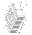
図4を参照する。図4には、水路規制板20に第1〜第4の熱交換チューブ31〜34が嵌合された状態が示されている。第1の熱交換チューブ31は、4つ設けられている。第1の熱交換チューブ31は、それぞれ、偏平形状を呈し内部に第1のフィン31cを有する。同様に、第2〜第4の熱交換チューブ32〜34は、4つの設けられており、それぞれ、扁平形状を呈すると共に内部に第2〜第4のフィン32c〜34cを有する。
Please refer to FIG. FIG. 4 shows a state where the first to fourth
第1〜第4の熱交換チューブ31〜34は、互いに同一の形状及び大きさを呈する。第1〜第4のフィン31c〜34cは、互いに同一の形状及び大きさを呈する。さらに、導入側エンドプレート41〜44及び排出側エンドプレート51〜54は、互いに同一の形状及び大きさを呈する。
The first to fourth
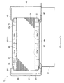
図2及び図5を参照する。水路規制板20の仕切板60の上部66は、上側ケース半体16の天井部16aに当接している。仕切板60の下部67は、下側ケース半体14の底部14aに当接している。
Please refer to FIG. 2 and FIG. An
なお、仕切板60の上部66は、上側ケース半体16の天井部16aに接合してもよい。同様に、仕切板60の下部67は、下側ケース半体14の底部14aに接合してもよい。
Note that the
第1のゲート板71の導入側端部75は、導入側連結プレート45と当接している。第1のゲート板71の排出側端部76は、排出側連結プレート55と当接している。
The introduction side end 75 of the
次に本発明の作用及び効果について説明する。 Next, the operation and effect of the present invention will be described.
図1及び図5を参照する。2次熱交換器12は、筒状のケース17と、導入側及び排出側エンドプレート41〜54と、導入側及び排出側連結プレート45,55と、第1〜第4の熱交換チューブ31〜34と、これらの熱交換チューブ31〜34の内部に配置されたフィンと、を有する。
Please refer to FIG. 1 and FIG. The
水は、ケース17、導入側及び排出側エンドプレート41〜54と、導入側及び排出側連結プレート45,55とにより囲まれる領域内を流れる。一方、1次熱交換器11を通過した燃焼ガスは、導入側連結プレート45の下部に形成された導入開口部47から2次熱交換器12に導入される。その後、燃焼ガスは第1〜第4の熱交換チューブ31〜34(図4参照)の内部を通過し、排出側蓋体56に形成された排出孔57から排出される。
The water flows in a region surrounded by the
水は、第1の熱交換チューブ31の周囲を流れるため、第の熱交換チューブ31には、内側に向かって潰れるように水圧が加わる。ここで、第1の熱交換チューブ31は、それぞれ、内部から第1のフィン31cにより支持されている。第1のフィン31cは、第1の熱交換チューブを31潰す方向に加わる力に抗する作用を有する。これにより、第1の熱交換チューブ31が水圧により潰されることを抑制できる。第2〜第4の熱交換チューブ32〜34も同様である。このような強度の高い第1〜第4の熱交換チューブ31〜34を用いることにより、強度の高い2次熱交換器を提供することができる。
Since water flows around the first
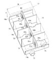
図6を参照する。ケース17の内部は、水の流れ方向を規制する水路規制板20によって複数の部屋に区画されている。即ち、ケース17の内部において、水は、一の部屋から隣接する部屋へ流れるよう規制されている。水が、水導入部13から水排出部15に向かって直接的に流れることを抑制できる(熱交換時において、第1〜第4の嵌合孔61a〜64aは、熱交換チューブ31〜34により塞がれている)。水の流路を長くすることができるため、より多くの熱エネルギを回収することができる。
Please refer to FIG. The inside of the
この水路規制板20は、ケース17の内部を仕切る仕切板60と、ケース17の内部を仕切ると共に水が通過可能な第1〜第3のゲート板71〜73と、からなる。水路規制板20は、板を組み合わせて構成されるため、ケース17内において、第1〜第4の熱交換チューブ31〜34(図1参照)が配置されるスペースを圧迫しない。水導入部13から導入された水は、第1〜第3の通過部81a〜83aを通過し、仕切板通過部65にて折り返され、さらに、第3の通過部83b〜第1の通過部81bを通過して、水排出部15から排出される。
The water
ここで、ゲート板71,72にそれぞれ形成され互いに隣接する第1,第2の通過部81a,82aは、下側ケース半体14の底部14aからの高さが異なる。第1の通過部81aは、第1の仕切板71の上部に形成されている。第2の通過部82bは、第2の仕切板72の下部に形成されている。そのため、第1の通過部81aから第2の通過部82bに向かう水は、下側ケース半体14の底部14aに対して斜めに流れる。他の隣接する通過部82a〜81bも同様である。水は、ケース17内を蛇行して流れるため、水の流路は長くなる。結果、より多くの熱エネルギを回収することができる。
Here, the first and
図4及び図5を参照する。仕切板60の下部67は下側ケース半体14の底部14aと当接している。即ち、第1の熱交換チューブ31は、導入側及び排出側エンドプレート41,51に支持されると共に、仕切板60にも支持される。そのため、第1の熱交換チューブ31の強度は高くなる。第2〜第4の熱交換チューブ32〜34及び仕切板60も、同様の構成である。そのため、第2〜第4の熱交換チューブ32〜34の強度も高くなる。
Please refer to FIG. 4 and FIG. The
図2及び図5を参照する。水路規制板20の仕切板60の上部66は、上側ケース半体16の天井部16aに当接している。さらに上記の通り、仕切板60の下部67は、下側ケース半体14の底部14aに当接している。第1のゲート板71の導入側端部75は、導入側連結プレート45と当接している。第1のゲート板71の排出側端部76は、排出側連結プレート55と当接している。即ち、ケース17と連結プレート45,55とからなる筐体は、水路規制板20により内部から支持される。そのため、ケース17と連結プレート45,55とからなる筐体の強度は高くなる。
<実施例2>
Please refer to FIG. 2 and FIG. An
<Example 2>
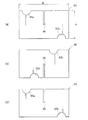
図7を参照する。次に、本発明の実施例2について説明する。実施例2では、第1〜第3のゲート板91〜93に形成される通過部91a〜93bの位置が異なる。その他の構成については、実施例1の2次熱交換器12と同様であり、符号を流用すると共に説明を省略する。
Please refer to FIG. Next, a second embodiment of the present invention will be described. In the second embodiment, the positions of the
第2のゲート板92に形成される第2の通過部92aは、第1,3のゲート板91,93に形成される第1の通過部91a,93aよりも第2のスリット95側に寄って形成されている。即ち、第2のスリット95から第2の第2の通過部92aまでの距離は、第1,第3のスリット94,96から第1,第3の通過部91a,93aまでの距離よりも短い。
The
即ち、隣り合うゲート板(例えば、第1のゲート板91と第2のゲート板92)に設けられたそれぞれの通過部(例えば、第1の通過部91aと第2の通過部92a)は、上下にオフセットされていると共に水平方向にもオフセットされている。その他の通過部(例えば、第2の通過部92aと第3の通過部93a)も同様の構成である。説明は省略する。
That is, the respective passage portions (for example, the
第1〜第3のゲート板91〜93を採用した2次熱交換器においても、本発明所定の効果を得ることができる。さらに、第1〜第3のゲート板91〜93によれば、上記の構成により、以下の特有の効果を得ることができる。
Also in the secondary heat exchanger employing the first to
第1〜第3のゲート板91〜93を採用した水路規制板が組み立てられた状態において(図6参照)、第1の通過部91aと第2の通過部92aは、底板14aからの距離が異なり、かつ、スリット94,95(仕切板60(図6参照))からの距離も異なる。そのため、水は、高さH方向だけでなく、幅W方向にも蛇行する。ケース17内の水の流路がより長くなり、より多くの熱エネルギを回収することができる。
<実施例3>
In a state where the water channel restriction plates adopting the first to
<Example 3>
図8を参照する。次に、本発明の実施例3について説明する。実施例3では、実施例1におけるゲート板71〜73(図3参照)の形状及び支持構造が異なる。その他の構成については、実施例1の2次熱交換器12と同様であり、符号を流用すると共に説明を省略する。
Please refer to FIG. Next, Embodiment 3 of the present invention will be described. In Example 3, the shape and support structure of the
仕切板60Aは、矩形状を呈し、第1の嵌合孔61a〜第4の嵌合孔64a及び仕切板通過部65が形成されている。
The
仕切板60Aの一面には、第1〜第3のゲート板71A〜73Aが接合されている。第1〜第3のゲート板71A〜73Aには、それぞれ、第1〜第3の通過部81a〜83aが形成されている。仕切板60Aの他面には、第1のゲート板〜第3のゲート板71B〜73Bが接合されている。第1のゲート板〜第3のゲート板71B〜73Bには、それぞれ、第1〜第3の通過部81b〜83bが形成されている。
<実施例4>
The first to
<Example 4>
図9を参照する。次に、本発明の実施例4について説明する。実施例4では、実施例3における第1〜第3のゲート板71A〜73A、及び、第1〜第3のゲート板71B〜73Bの支持構造が異なる。その他の構成については、実施例1の2次熱交換器12と同様であり、符号を流用すると共に説明を省略する。
Please refer to FIG. Next, a fourth embodiment of the present invention will be described. In the fourth embodiment, the support structures of the first to
下側ケース半体14の底部14aには、第1のゲート板71A,第2のゲート板72B,第3のゲート板73Aが接合されている。上側ケース半体16の天井部16aには、第1のゲート板71B,第2のゲート板72A,第3のゲート板73Bが接合されている。
A
なお、本発明は、本発明の作用及び効果を奏する限りにおいて、実施例1〜4の構成及びこれらの組み合わせに限定されるものではない。 In addition, as long as there exists an effect | action and effect of this invention, this invention is not limited to the structure of Examples 1-4, and these combination.
本発明のガス給湯器は、家庭に設置されるガス給湯器に好適である。 The gas water heater of the present invention is suitable for a gas water heater installed at home.
10…ガス給湯器
11…1次熱交換器
12…2次熱交換器
13…水導入部
14…下側ケース半体
15…水排出部
16…上側ケース半体
17…ケース
31〜34…第1のチューブ〜第4のチューブ
41〜44…第1の導入側エンドプレート〜第4の導入側エンドプレート
45…導入側連結プレート
46…導入側蓋体
47…導入開口部
51〜54…第1の排出側エンドプレート〜第4の排出側エンドプレート
55…排出側エンドプレート
56…排出側蓋体
57…排出孔
60…仕切板
61〜64…第1の仕切部〜第4の仕切部
65…仕切板通過部
66…上部
67…下部
71〜73…第1のゲート板〜第3のゲート板
75…導入側端部
76…排出側端部
81a,b〜83a,b…第1の通過部〜第3の通過部
91a,b〜93a,b…第1の通過部〜第3の通過部
DESCRIPTION OF
Claims (4)
前記2次熱交換器は、筒状のケースと、このケースの両端部をそれぞれ塞ぐエンドプレートと、これらのエンドプレートによって両端が支持され内部に前記燃焼ガスが流される複数の熱交換チューブと、これらの熱交換チューブの内部に配置されたフィンと、からなることを特徴とするガス給湯器。 A primary heat exchanger that is disposed immediately above the burner through which the combustion gas generated in the burner passes, and a secondary heat exchanger through which the combustion gas that has passed through the primary heat exchanger flows, In a gas water heater in which water flowing through the primary heat exchanger and the secondary heat exchanger is heated by combustion gas,
The secondary heat exchanger includes a cylindrical case, end plates that close both ends of the case, a plurality of heat exchange tubes that are supported at both ends by the end plates and into which the combustion gas flows, A gas water heater comprising: fins arranged inside these heat exchange tubes.
前記ゲート板には、前記水が通過する通過部が形成され、前記水の流れ方向で互いに隣接する前記通過部は、前記ケースの底部からの高さが異なることを特徴とする請求項2記載のガス給湯器。 The water passage regulating body is composed of a partition plate for partitioning the inside of the case, and a gate plate for partitioning the interior of the case and allowing the water to pass through,
3. The gate plate is formed with a passage portion through which the water passes, and the passage portions adjacent to each other in the water flow direction have different heights from the bottom of the case. Gas water heater.
Priority Applications (1)
| Application Number | Priority Date | Filing Date | Title |
|---|---|---|---|
| JP2016060863A JP6595381B2 (en) | 2016-03-24 | 2016-03-24 | Gas water heater |
Applications Claiming Priority (1)
| Application Number | Priority Date | Filing Date | Title |
|---|---|---|---|
| JP2016060863A JP6595381B2 (en) | 2016-03-24 | 2016-03-24 | Gas water heater |
Publications (2)
| Publication Number | Publication Date |
|---|---|
| JP2017172902A true JP2017172902A (en) | 2017-09-28 |
| JP6595381B2 JP6595381B2 (en) | 2019-10-23 |
Family
ID=59971876
Family Applications (1)
| Application Number | Title | Priority Date | Filing Date |
|---|---|---|---|
| JP2016060863A Expired - Fee Related JP6595381B2 (en) | 2016-03-24 | 2016-03-24 | Gas water heater |
Country Status (1)
| Country | Link |
|---|---|
| JP (1) | JP6595381B2 (en) |
Cited By (1)
| Publication number | Priority date | Publication date | Assignee | Title |
|---|---|---|---|---|
| CN112556166A (en) * | 2019-09-26 | 2021-03-26 | 株式会社能率 | Water heating device |
Citations (6)
| Publication number | Priority date | Publication date | Assignee | Title |
|---|---|---|---|---|
| EP0271434A2 (en) * | 1986-12-06 | 1988-06-15 | Joh. Vaillant GmbH u. Co. | Steel boiler |
| JPH04100564U (en) * | 1991-01-30 | 1992-08-31 | ||
| JP2006084054A (en) * | 2004-09-14 | 2006-03-30 | Toyotomi Co Ltd | Structure of heat exchanger for hot water |
| JP2011242023A (en) * | 2010-05-17 | 2011-12-01 | Chofu Seisakusho Co Ltd | Liquid fuel water heater |
| EP2437022A2 (en) * | 2010-10-01 | 2012-04-04 | Aic S.A. | Gas-to-liquid pipe heat exchanger, in particular for domestic boiler |
| WO2015004292A1 (en) * | 2013-07-12 | 2015-01-15 | Cordón Urbiola Jose Luis | Exchanger for heating boilers |
-
2016
- 2016-03-24 JP JP2016060863A patent/JP6595381B2/en not_active Expired - Fee Related
Patent Citations (6)
| Publication number | Priority date | Publication date | Assignee | Title |
|---|---|---|---|---|
| EP0271434A2 (en) * | 1986-12-06 | 1988-06-15 | Joh. Vaillant GmbH u. Co. | Steel boiler |
| JPH04100564U (en) * | 1991-01-30 | 1992-08-31 | ||
| JP2006084054A (en) * | 2004-09-14 | 2006-03-30 | Toyotomi Co Ltd | Structure of heat exchanger for hot water |
| JP2011242023A (en) * | 2010-05-17 | 2011-12-01 | Chofu Seisakusho Co Ltd | Liquid fuel water heater |
| EP2437022A2 (en) * | 2010-10-01 | 2012-04-04 | Aic S.A. | Gas-to-liquid pipe heat exchanger, in particular for domestic boiler |
| WO2015004292A1 (en) * | 2013-07-12 | 2015-01-15 | Cordón Urbiola Jose Luis | Exchanger for heating boilers |
Cited By (2)
| Publication number | Priority date | Publication date | Assignee | Title |
|---|---|---|---|---|
| CN112556166A (en) * | 2019-09-26 | 2021-03-26 | 株式会社能率 | Water heating device |
| CN112556166B (en) * | 2019-09-26 | 2023-04-07 | 株式会社能率 | Water heating device |
Also Published As
| Publication number | Publication date |
|---|---|
| JP6595381B2 (en) | 2019-10-23 |
Similar Documents
| Publication | Publication Date | Title |
|---|---|---|
| EP2889570B1 (en) | Heat exchanger | |
| CN110822954B (en) | Heat exchanger | |
| JP6162598B2 (en) | Latent heat exchanger and hot water supply apparatus including the same | |
| JP2019113280A (en) | Heat exchange device and heat source machine | |
| AU2017228523A1 (en) | Heat exchanger and hot water apparatus | |
| JP6595381B2 (en) | Gas water heater | |
| JP6122266B2 (en) | Heat exchanger | |
| JP7357208B2 (en) | Heat exchanger and water heating equipment equipped with the same | |
| EP3076102A1 (en) | Heat exchanger and gas boiler using the same | |
| US20170211845A1 (en) | Device for dispensing a heated fluid | |
| JP7385110B2 (en) | hot water equipment | |
| JP2006342997A (en) | Heat exchanger | |
| CN113028646B (en) | Heat exchanger and warm water device | |
| JP4318037B2 (en) | Heat exchanger | |
| JP2017172903A (en) | Gas water heater | |
| KR20060104174A (en) | Waste heat recovery machine | |
| JP4312640B2 (en) | Stacked heat exchanger | |
| JP6449190B2 (en) | Gas water heater | |
| KR200490258Y1 (en) | Heat Exchanger | |
| JP2005147426A (en) | Heat exchanger | |
| JP2008025976A (en) | Heat exchanger and hot water device | |
| JP2005321171A (en) | Instantaneous heating device and water heater | |
| KR100512297B1 (en) | Steam and warm water boiler | |
| JP7365553B2 (en) | heating water heater | |
| JP2014238226A (en) | Panel radiator |
Legal Events
| Date | Code | Title | Description |
|---|---|---|---|
| A621 | Written request for application examination |
Free format text: JAPANESE INTERMEDIATE CODE: A621 Effective date: 20180322 |
|
| A131 | Notification of reasons for refusal |
Free format text: JAPANESE INTERMEDIATE CODE: A131 Effective date: 20181204 |
|
| A977 | Report on retrieval |
Free format text: JAPANESE INTERMEDIATE CODE: A971007 Effective date: 20181130 |
|
| A521 | Request for written amendment filed |
Free format text: JAPANESE INTERMEDIATE CODE: A523 Effective date: 20190130 |
|
| A131 | Notification of reasons for refusal |
Free format text: JAPANESE INTERMEDIATE CODE: A131 Effective date: 20190507 |
|
| A521 | Request for written amendment filed |
Free format text: JAPANESE INTERMEDIATE CODE: A523 Effective date: 20190618 |
|
| TRDD | Decision of grant or rejection written | ||
| A01 | Written decision to grant a patent or to grant a registration (utility model) |
Free format text: JAPANESE INTERMEDIATE CODE: A01 Effective date: 20190903 |
|
| A61 | First payment of annual fees (during grant procedure) |
Free format text: JAPANESE INTERMEDIATE CODE: A61 Effective date: 20190926 |
|
| R150 | Certificate of patent or registration of utility model |
Ref document number: 6595381 Country of ref document: JP Free format text: JAPANESE INTERMEDIATE CODE: R150 |
|
| LAPS | Cancellation because of no payment of annual fees |