JP2017178145A - Auxiliary steering gear of vehicle - Google Patents
Auxiliary steering gear of vehicle Download PDFInfo
- Publication number
- JP2017178145A JP2017178145A JP2016070782A JP2016070782A JP2017178145A JP 2017178145 A JP2017178145 A JP 2017178145A JP 2016070782 A JP2016070782 A JP 2016070782A JP 2016070782 A JP2016070782 A JP 2016070782A JP 2017178145 A JP2017178145 A JP 2017178145A
- Authority
- JP
- Japan
- Prior art keywords
- steering
- vehicle
- armrest bars
- bars
- right armrest
- Prior art date
- Legal status (The legal status is an assumption and is not a legal conclusion. Google has not performed a legal analysis and makes no representation as to the accuracy of the status listed.)
- Granted
Links
Images


Landscapes
- Steering Controls (AREA)
- Steering Control In Accordance With Driving Conditions (AREA)
- Mechanical Control Devices (AREA)
Abstract
Description
本発明は、たとえば自動車といった車両の補助操舵装置に関する。 The present invention relates to an auxiliary steering device for a vehicle such as an automobile.
自動車といった車両では、特許文献1にあるように、シートに着座した乗員がシート前側に配置されたハンドルを操作し、これにより車両の進行方向が制御される。 In a vehicle such as an automobile, as disclosed in Patent Document 1, an occupant seated on a seat operates a handle disposed on the front side of the seat, and thereby the traveling direction of the vehicle is controlled.
ところで、自動車といった車両では、近年、自動運転に向けた技術開発が開始されている。たとえば、ドライバがハンドルを操舵しなくても、車両が車線をキープし、目的地に向けて適切に右左折することができるようにことが望まれている。これにより、ドライバの運転負担を軽減し、安全性に貢献し得る。 By the way, in vehicles such as automobiles, technical development for automatic driving has recently started. For example, it is desired that the vehicle can keep the lane and appropriately turn right and left toward the destination even if the driver does not steer the steering wheel. This can reduce the driving burden on the driver and contribute to safety.
しかしながら、入場が制限されたサーキットとは異なり、他の自動車やその他の物体が存在する一般道や高速道路においては、様々な事象が想定し得るため、ドライバがハンドルを一切操舵しないようにできるまでにはより一層の技術開発が必要となる。特に、想定外の事象が起きた緊急時には、ドライバがハンドルを操作する必要があるものと予想される。
このように、自動運転では、緊急時にはドライバにハンドル操作を要求することが重要である。
However, unlike a circuit where entry is restricted, various events can be assumed on ordinary roads and highways where other cars and other objects exist, so until the driver can avoid steering the steering wheel at all Will require further technological development. In particular, in an emergency where an unexpected event occurs, it is expected that the driver needs to operate the steering wheel.
Thus, in automatic driving, it is important to request a steering wheel operation from the driver in an emergency.
その一方で、自動運転においては、ドライバの注意が運転から離れやすい。特に、ハンドルから手を放してしまうタイミングも生じる可能性がある。ハンドルから手を放している間に緊急事態が発生すると、ドライバはあわてて腕を上げてハンドルを握り、その上でハンドルを操作しなければならない。一刻を争う緊急事態においては、このようなタイムロスが問題となる可能性がある。 On the other hand, in automatic driving, the driver's attention tends to leave the driving. In particular, there may be a timing when the hand is released from the handle. If an emergency occurs while letting go of the handle, the driver must hurry to raise the arm and grip the handle, and then operate the handle. Such time loss can be a problem in a timely emergency.
このように、車両では、自動運転中の緊急時などにおいて操舵操作が容易にできるようにすることが求められている。 As described above, the vehicle is required to easily perform the steering operation in an emergency or the like during automatic driving.
本発明に係る車両の補助操舵装置は、乗員がシートに着座して前方のハンドルを操作する車両の補助操舵装置であって、前記シートの左右に設けられ、前記シートに着座した乗員が腕をのせることができる左右のアームレストと、左右の前記アームレストの前端部に設けられる左右のアームレストバーと、左右の前記アームレストバーに対する操作を検出する左右のセンサと、左右の前記センサの検出に応じて前記車両の操舵を制御する制御部と、を有する。 An auxiliary steering device for a vehicle according to the present invention is an auxiliary steering device for a vehicle in which an occupant sits on a seat and operates a front handle, provided on the left and right sides of the seat, and the occupant seated on the seat holds an arm. Left and right armrests that can be placed, left and right armrest bars provided at the front ends of the left and right armrests, left and right sensors that detect operations on the left and right armrest bars, and according to detection of the left and right sensors A control unit that controls steering of the vehicle.
好適には、左右の前記アームレストバーは、直線棒形状であり、左右の前記アームレストの前端部において上向きに立設される、とよい。 Preferably, the left and right armrest bars have a straight bar shape, and are erected upward at the front end portions of the left and right armrests.
好適には、左右の前記アームレストバーは、円弧棒形状であり、左右の前記アームレストバーの円弧同士が共通の仮想円に沿うように、左右の前記アームレストの前端部において上向きに立設される、とよい。 Preferably, the left and right armrest bars have an arc bar shape, and are erected upward at the front end portions of the left and right armrests so that the arcs of the left and right armrest bars are along a common virtual circle. Good.
好適には、前記制御部は、乗員が前記ハンドルを操作しない状態で前記車両の操舵を制御する自動運転中に、左右の前記アームレストバーによる操舵を有効とする、とよい。 Preferably, the control unit validates steering by the left and right armrest bars during an automatic operation in which an occupant controls steering of the vehicle without operating the steering wheel.
好適には、前記制御部は、自動運転中において障害の可能性を検出した場合に、左右の前記アームレストバーによる操舵を有効とする、とよい。 Preferably, the control unit may enable steering by the left and right armrest bars when the possibility of a failure is detected during automatic driving.
好適には、左右各々の前記センサは、左右の前記アームレストバーの棒軸方向に沿った操作を検出し、前記制御部は、左右の前記アームレストバーの棒軸方向の操作が上下逆である場合、その操作方向へ前記ハンドルが操作されたとして前記車両の操舵を制御する、とよい。 Preferably, each of the left and right sensors detects an operation along the bar axis direction of the left and right armrest bars, and the control unit detects that the operation of the left and right armrest bars in the bar axis direction is upside down. The steering of the vehicle may be controlled on the assumption that the steering wheel is operated in the operation direction.
本発明では、左右のアームレストの前端部に左右のアームレストバーが設けられ、この左右のアームレストバーに対する操作に応じて車両の操舵制御が実行される。よって、シートに着座した乗員は、左右のアームレストに腕を載せたまま動かすことなく手で左右のアームレストバーを握り、車両の操舵操作を実施することができる。緊急事態においても最小限のタイムロスで容易に操作対応することができる。 In the present invention, left and right armrest bars are provided at the front ends of the left and right armrests, and vehicle steering control is executed in accordance with an operation on the left and right armrest bars. Therefore, the occupant seated on the seat can perform the steering operation of the vehicle by grasping the left and right armrest bars by hand without moving the arms on the left and right armrests. Even in an emergency, it can be easily handled with minimal time loss.
以下、本発明の実施形態を、図面に基づいて説明する。 Hereinafter, embodiments of the present invention will be described with reference to the drawings.
図1は、本発明の実施形態に係る自動車1の側面透視図である。自動車1は、車両の一例である。 FIG. 1 is a side perspective view of an automobile 1 according to an embodiment of the present invention. The automobile 1 is an example of a vehicle.
図1の自動車1は、前室2、乗員室3、および後室4からなる車体を有する。前室2には、エンジン、電気モータ等の動力ユニットが配置される。後室4には、ラッゲージスペースが設けられる。乗員室3には、乗車した乗員が着座するシート5が前後二列で設けられる。また、乗員室3において運転者用のシート5の前には、ハンドル6、アクセルペダル、ブレーキペダルなどの操作部材が設けられる。ハンドル6は、ダッシュボードから後向きに突出して設けられる。
An automobile 1 in FIG. 1 has a vehicle body including a
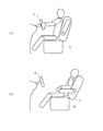
図2は、乗員の乗車状態の説明図である。
図2(A)は、乗員がハンドル6を操作する通常運転時での乗車状態である。運転者用のシート5に着座した乗員は、腕を前へ伸ばし、前方のハンドル6を手で握る。この状態でハンドル6を右回りまたは左回りに回転操作する。これにより、走行する自動車1は右折または右左折できる。自動車1は、乗員の操作に従って走行する。
FIG. 2 is an explanatory diagram of a passenger's boarding state.
FIG. 2A shows a riding state during normal driving in which the occupant operates the
図2(B)は、乗員が操作しない自動運転時での一例の乗車状態である。図2(A)の通常運転時と比べて、シート5の座部が後へ下がり、シート5の背部は後へリクライニングしている。乗員は、両腕をアームレスト7に置いて、くつろいだ姿勢にいる。このような運転姿勢は自動運転中であっても禁止されるべきものであると常識的に考えられるが、乗員によっては自動運転中にこのような運転姿勢を取ってしまう可能性がある。
そして、乗員がこのようなくつろいだ運転姿勢である状況下で、たとえば衝突等の危険事由が発生した場合、乗員はあわてて上体を起こし、腕を前に伸ばし上げ、ハンドル6を握らなければならない。そして、その上でハンドル6を操作しなければならない。入場が制限されたサーキット場とは異なり、他の自動車1やその他の物体が存在する一般道や高速道路においては、様々な事象が想定し得るため、このような緊急操作が必要になる場面は少なくない。一刻を争う緊急事態においては、このようなタイムロスが問題となる可能性がある。特に、他のことに気をとられていた場合、さらにタイムロスが生じる可能性がある。
このように、自動車1では、自動運転中の緊急時などにおいて操舵操作が容易にできるようにすることが求められている。
FIG. 2B shows an example of a boarding state during automatic driving that is not operated by a passenger. Compared to the normal operation of FIG. 2A, the seat portion of the
And, in the situation where the occupant is in such a relaxed driving posture, for example, when a danger such as a collision occurs, the occupant must wake up, raise his arm forward, and hold the
As described above, the automobile 1 is required to be able to easily perform a steering operation in an emergency or the like during automatic driving.
図3は、本実施形態に係る自動車1の補助操舵装置10の説明図である。図3(A)は右側面図であり、図3(B)は正面図であり、図3(C)は上面図である。
シート5の背部の左右両側には、シート5に着座した乗員が腕をのせることができる左右のアームレスト7が図示される。アームレスト7は、背部から前へ延在する。
左右のアームレスト7の前端部には、左右のアームレストバー11が設けられる。
アームレストバー11は、直線棒形状を有する。直線棒形状のアームレストバー11は、アームレスト7の前端部から上向きに突出するように立設される。
そして、乗員は、腕をアームレスト7に置いたくつろいだ姿勢のままで、左右のアームレストバー11を左右の手で握ることができる。
FIG. 3 is an explanatory diagram of the
On the left and right sides of the back portion of the
Left and right armrest bars 11 are provided at the front ends of the left and
The
The occupant can hold the left and right armrest bars 11 with his left and right hands while keeping his relaxed posture with his arms placed on the
図4は、図3の自動車1の補助操舵装置10の制御系のブロック図である。
FIG. 4 is a block diagram of a control system of the
図4の制御系は、撮像デバイス21、速度センサ22、アームレストバーセンサ23、タイマ24、およびこれらが接続された制御部25、を有する。
また、図4には、制御部25に接続された制御対象であるステアリングモータ26が併せて図示されている。ステアリングモータ26は、自動車1のステアリング装置に設けられ、自動操舵等のために操舵駆動するものである。
The control system in FIG. 4 includes an
FIG. 4 also shows a
撮像デバイス21は、たとえば一対の撮像素子であり、図に示すように乗員室3のルーフやフロントガラスに前向きに設けられ、自動車1の前方の周辺状況を撮像により観測する。制御部25は、撮像された画像から、自動車1の周辺状況として、たとえば自動車1前方の他の自動車1などの障害物を特定し、該障害物の衝突の可能性を判断し得る。これにより、衝突前の自動車1の走行状況を検出し得る。
The
速度センサ22は、車体に固定して設けられ、自動車1の走行状況として自動車1の速度を検出する。
The
アームレストバーセンサ23は、アームレストバー11に対する操作を検出する。アームレストバーセンサ23は、たとえばアームレストバー11の周面に巻き付けらたれ感圧分布シートでよい。これにより、アームレストバーセンサ23の感圧位置の変化により、アームレストバー11の棒軸方向に沿った操作を検出することができる。
The
タイマ24は、時間を計測する。
The
制御部25は、これらセンサの検出信号に基づいて、ステアリングモータ26による自動操舵制御または補助操舵制御を実行する。
The
図5は、図4の制御部25による操舵制御の一例のフローチャートである。制御部25は、図5の処理を周期的に繰り返し実行する。
FIG. 5 is a flowchart of an example of steering control by the
自動操舵制御または補助操舵制御を実行するために、制御部25は、自動運転の要否を判断する(ステップST1)。たとえば図示外の自動運転の開始ボタンなどが操作された場合、制御部25は、自動運転が必要と判断する。それ以外の場合には不要と判断し、図5の処理を終了する。
In order to execute the automatic steering control or the auxiliary steering control, the
自動運転が必要と判断した場合、制御部25は、自動制御を開始する(ステップST2)。自動制御において、制御部25は、自動車1の操舵、速度、加速度などを制御する。
When it is determined that automatic operation is necessary, the
また、制御部25は、警告の要否を判断する(ステップST3)。制御部25は、たとえば撮像デバイス21による撮像画像や自車速度に基づいてたとえば正面方向に存在する物体との衝突の可能性を判断する。そして、衝突の可能性がある場合、警告が必要であると判断する。それ以外の場合は、不要と判断する。
Further, the
警告が必要と判断した場合、制御部25は、自動運転中でのアームレストバー11などによる操舵を有効とし、警告を報知する(ステップST4)。警告は、たとえば音声や表示により実施すればよい。
When it is determined that a warning is necessary, the
警告を報知した後、制御部25は、乗員による操舵を検出する(ステップST5)。この中には、図3の補助操舵装置10の操作も含まれる。
そして、左右のアームレストバー11に対する所定の操作が検出された場合、制御部25は、その操作量または操作力に応じたステアリング制御を実行する(ステップST6)。
たとえば左右のアームレストバー11の棒軸方向の操作が上下逆である場合、制御部25は、その操作方向へハンドル6が操作されたものとして、ステアリングモータ26を操作方向へ駆動する。また、アームレストバーセンサ23での感圧位置の変化量に基づいて、ステアリングモータ26の駆動量を制御する。
この他にもたとえば、制御部25は、アームレストバーセンサ23を握る力が所定の閾値以上である場合にのみ、左右のアームレストバー11の操作に基づく操舵を実行してもよい。
After notifying the warning, the
When a predetermined operation on the left and right armrest bars 11 is detected, the
For example, when the operation of the left and right armrest bars 11 in the bar axis direction is upside down, the
In addition, for example, the
以上のように、本実施形態では、左右のアームレスト7の前端部に左右のアームレストバー11が設けられ、この左右のアームレストバー11に対する操作に応じて自動車1の操舵制御が実行される。よって、シート5に着座した乗員は、左右のアームレスト7に腕を載せたまま動かすことなく手で左右のアームレストバー11を握り、自動車1の操舵操作を実施することができる。緊急事態においても最小限のタイムロスで操作対応することができる。
As described above, in the present embodiment, the left and right armrest bars 11 are provided at the front end portions of the left and
また、本実施形態では、左右のアームレストバー11は、直線棒形状であり、左右のアームレスト7の前端部において上向きに立設される。よって、左右のアームレスト7に下腕を載せたまま、アームレストバー11を握ることができる。
In the present embodiment, the left and right armrest bars 11 have a straight bar shape and are erected upward at the front end portions of the left and
また、本実施形態では、制御部25は、乗員がハンドル6を操作しない状態で自動車1の操舵を制御する自動運転中に、左右のアームレストバー11による操舵を有効とする。よって、自動運転中以外のタイミングでは、左右のアームレストバー11に対する操作により操舵制御が実行されない。乗員による通常運転中に影響を与えないようにできる。
Further, in the present embodiment, the
また、本実施形態では、制御部25は、自動運転中において障害の可能性を検出した場合に、左右のアームレストバー11による操舵を有効とする。よって、自動運転中であっても障害の可能性が検出されないタイミングでは、左右のアームレストバー11に対する操作により操舵制御が実行されない。自動運転中に誤って又は他の目的で左右のアームレストバー11に触れた場合でも、自動運転に影響を与えないようにできる。
In the present embodiment, the
また、本実施形態では、左右各々のセンサは、左右のアームレストバー11の棒軸方向に沿った操作を検出し、制御部25は、左右のアームレストバー11の棒軸方向の操作が上下逆である場合、その操作方向へハンドル6が操作されたとして自動車1の操舵を制御する。よって、これ以外の操作、または意図しない操作が左右のアームレストバー11に対してなされたとしても、操舵制御が実行されない。自動運転中に誤って又は他の目的で左右のアームレストバー11に触れた場合でも、自動運転に影響を与えないようにできる。
In the present embodiment, each of the left and right sensors detects an operation along the bar axis direction of the left and right armrest bars 11, and the
以上の実施形態は、本発明の好適な実施形態の例であるが、本発明は、これに限定されるものではなく、発明の要旨を逸脱しない範囲において種々の変形または変更が可能である。 The above embodiment is an example of a preferred embodiment of the present invention, but the present invention is not limited to this, and various modifications or changes can be made without departing from the scope of the invention.
図6は、図3の自動車1の補助操舵装置10の変形例の説明図である。
図6において、左右のアームレストバー11は、円弧棒形状である。そして、左右のアームレストバー11は、それらの円弧同士が共通の仮想円に沿うように、左右のアームレスト7の前端部において上向きに立設される。
これにより、左右のアームレスト7に下腕を載せたまま、アームレストバー11を握ることができる。しかも、左右のアームレストバー11が円形のハンドル6を模した状態にあるため、乗員は、通常のハンドル6操作と同様の感覚で左右のアームレストバー11を操作することができる。
FIG. 6 is an explanatory view of a modification of the
In FIG. 6, the left and right armrest bars 11 have an arc bar shape. The left and right armrest bars 11 are erected upward at the front end portions of the left and
As a result, the
上記実施形態では、制御部25は、自動運転中において障害の可能性を検出した場合に、左右のアームレストバー11による操舵を有効としている。
この他にもたとえば、制御部25は、自動運転を開始したタイミングで、アームレストバー11などによる操舵を有効としてもよい。これにより、自動運転中にハンドル6ではなく、左右のアームレストバー11を操作することにより、操舵を実施することができる。
In the above embodiment, the
In addition to this, for example, the
1…自動車(車両)
2…前室
3…乗員室
4…後室
5…シート
6…ハンドル
7…アームレスト
10…補助操舵装置
11…アームレストバー
21…撮像デバイス
22…速度センサ
23…アームレストバーセンサ(センサ)
24…タイマ
25…制御部
26…ステアリングモータ
1 ... Automobile (vehicle)
2 ...
24 ...
Claims (6)
前記シートの左右に設けられ、前記シートに着座した乗員が腕をのせることができる左右のアームレストと、
左右の前記アームレストの前端部に設けられる左右のアームレストバーと、
左右の前記アームレストバーに対する操作を検出する左右のセンサと、
左右の前記センサの検出に応じて前記車両の操舵制御を実行する制御部と、
を有する、
車両の補助操舵装置。 An auxiliary steering device for a vehicle in which an occupant sits on a seat and operates a front handle,
Left and right armrests provided on the left and right of the seat, on which an occupant seated on the seat can put arms;
Left and right armrest bars provided at the front ends of the left and right armrests;
Left and right sensors for detecting operations on the left and right armrest bars;
A control unit that executes steering control of the vehicle in response to detection of the left and right sensors;
Having
Auxiliary steering device for vehicles.
請求項1記載の車両の補助操舵装置。 The left and right armrest bars have a straight bar shape and are erected upward at the front end portions of the left and right armrests,
The auxiliary steering device for a vehicle according to claim 1.
請求項1記載の車両の補助操舵装置。 The left and right armrest bars have an arc bar shape, and are erected upward at the front end portions of the left and right armrests so that the arcs of the left and right armrest bars are along a common virtual circle.
The auxiliary steering device for a vehicle according to claim 1.
請求項1から3のいずれか一項記載の車両の補助操舵装置。 The control unit validates steering by the left and right armrest bars during automatic driving in which the occupant controls steering of the vehicle without operating the steering wheel.
The auxiliary steering device for a vehicle according to any one of claims 1 to 3.
請求項4記載の車両の補助操舵装置。 When the controller detects the possibility of failure during automatic driving, it enables steering by the left and right armrest bars,
The auxiliary steering device for a vehicle according to claim 4.
前記制御部は、左右の前記アームレストバーの棒軸方向の操作が上下逆である場合、その操作方向へ前記ハンドルが操作されたとして前記車両の操舵を制御する、
請求項1から5のいずれか一項記載の車両の補助操舵装置。
Each of the left and right sensors detects an operation along the bar axis direction of the left and right armrest bars,
When the operation of the left and right armrest bars in the bar axis direction is upside down, the control unit controls the steering of the vehicle on the assumption that the handle is operated in the operation direction.
The auxiliary steering device for a vehicle according to any one of claims 1 to 5.
Priority Applications (1)
| Application Number | Priority Date | Filing Date | Title |
|---|---|---|---|
| JP2016070782A JP6631955B2 (en) | 2016-03-31 | 2016-03-31 | Auxiliary steering system for vehicles |
Applications Claiming Priority (1)
| Application Number | Priority Date | Filing Date | Title |
|---|---|---|---|
| JP2016070782A JP6631955B2 (en) | 2016-03-31 | 2016-03-31 | Auxiliary steering system for vehicles |
Publications (2)
| Publication Number | Publication Date |
|---|---|
| JP2017178145A true JP2017178145A (en) | 2017-10-05 |
| JP6631955B2 JP6631955B2 (en) | 2020-01-15 |
Family
ID=60003370
Family Applications (1)
| Application Number | Title | Priority Date | Filing Date |
|---|---|---|---|
| JP2016070782A Active JP6631955B2 (en) | 2016-03-31 | 2016-03-31 | Auxiliary steering system for vehicles |
Country Status (1)
| Country | Link |
|---|---|
| JP (1) | JP6631955B2 (en) |
Cited By (3)
| Publication number | Priority date | Publication date | Assignee | Title |
|---|---|---|---|---|
| JP2017206153A (en) * | 2016-05-19 | 2017-11-24 | 本田技研工業株式会社 | Vehicle control system, vehicle control method, and vehicle control program |
| FR3094290A1 (en) * | 2019-03-29 | 2020-10-02 | Psa Automobiles Sa | Vehicle with an armrest fitted with a device for controlling at least one function of the vehicle |
| WO2026038294A1 (en) * | 2024-08-13 | 2026-02-19 | 日産自動車株式会社 | Information processing method and information processing device |
Citations (4)
| Publication number | Priority date | Publication date | Assignee | Title |
|---|---|---|---|---|
| JPH0834353A (en) * | 1994-05-18 | 1996-02-06 | Toyota Motor Corp | Vehicle steering system |
| JPH1081242A (en) * | 1996-06-26 | 1998-03-31 | Daimler Benz Ag | Operational element device for controlling longitudinal motion and traverse motion of automobile |
| US20040129488A1 (en) * | 2003-01-06 | 2004-07-08 | Chernoff Adrian B. | Rotary driver control input device |
| JP2006273202A (en) * | 2005-03-30 | 2006-10-12 | Honda Motor Co Ltd | Mobile driving device |
-
2016
- 2016-03-31 JP JP2016070782A patent/JP6631955B2/en active Active
Patent Citations (4)
| Publication number | Priority date | Publication date | Assignee | Title |
|---|---|---|---|---|
| JPH0834353A (en) * | 1994-05-18 | 1996-02-06 | Toyota Motor Corp | Vehicle steering system |
| JPH1081242A (en) * | 1996-06-26 | 1998-03-31 | Daimler Benz Ag | Operational element device for controlling longitudinal motion and traverse motion of automobile |
| US20040129488A1 (en) * | 2003-01-06 | 2004-07-08 | Chernoff Adrian B. | Rotary driver control input device |
| JP2006273202A (en) * | 2005-03-30 | 2006-10-12 | Honda Motor Co Ltd | Mobile driving device |
Cited By (4)
| Publication number | Priority date | Publication date | Assignee | Title |
|---|---|---|---|---|
| JP2017206153A (en) * | 2016-05-19 | 2017-11-24 | 本田技研工業株式会社 | Vehicle control system, vehicle control method, and vehicle control program |
| US10507843B2 (en) | 2016-05-19 | 2019-12-17 | Honda Motor Co., Ltd. | Vehicle control system, vehicle control method, and vehicle control program |
| FR3094290A1 (en) * | 2019-03-29 | 2020-10-02 | Psa Automobiles Sa | Vehicle with an armrest fitted with a device for controlling at least one function of the vehicle |
| WO2026038294A1 (en) * | 2024-08-13 | 2026-02-19 | 日産自動車株式会社 | Information processing method and information processing device |
Also Published As
| Publication number | Publication date |
|---|---|
| JP6631955B2 (en) | 2020-01-15 |
Similar Documents
| Publication | Publication Date | Title |
|---|---|---|
| US12195023B2 (en) | Vehicle control system | |
| US10252725B2 (en) | Vehicle stop apparatus | |
| EP2862553B1 (en) | Manually propelled vehicle | |
| US8942880B2 (en) | Method and device for operating a driver assistance system of a vehicle | |
| JP6332637B2 (en) | Driving assistance device | |
| KR101440054B1 (en) | Electric wheelchair and control method thereof | |
| JP2008273521A (en) | Automatic driving device for moving objects | |
| JP2022120852A (en) | vehicle control system | |
| JP6414514B2 (en) | Driving assistance device | |
| JP6855235B2 (en) | Driving operation device for automobiles and driving operation method for automobiles | |
| JP2018131081A (en) | Lane departure inhibition device | |
| JP6631955B2 (en) | Auxiliary steering system for vehicles | |
| JP2002264826A (en) | Automatic driving system for moving objects | |
| JP6136919B2 (en) | Inverted mobile device | |
| JP6409038B2 (en) | Vehicle occupant protection device | |
| JP6326240B2 (en) | Control method of moving body and its maximum speed | |
| JP2022069594A (en) | Vehicle control system | |
| JP6905811B2 (en) | Vehicle collision input reduction device | |
| JP4296422B2 (en) | Ottoman device for vehicle | |
| JP2020117091A (en) | Vehicle control device and vehicle | |
| JP2022105596A (en) | Occupant protection system | |
| JP4538902B2 (en) | Control device for vehicle steering mechanism | |
| JP2025057849A (en) | Seat control device, seat control method and program | |
| JP2018052447A (en) | Vehicle occupant protection device | |
| JP2008186122A (en) | Vehicle occupant protection device |
Legal Events
| Date | Code | Title | Description |
|---|---|---|---|
| A621 | Written request for application examination |
Free format text: JAPANESE INTERMEDIATE CODE: A621 Effective date: 20181220 |
|
| TRDD | Decision of grant or rejection written | ||
| A01 | Written decision to grant a patent or to grant a registration (utility model) |
Free format text: JAPANESE INTERMEDIATE CODE: A01 Effective date: 20191105 |
|
| A977 | Report on retrieval |
Free format text: JAPANESE INTERMEDIATE CODE: A971007 Effective date: 20191031 |
|
| A61 | First payment of annual fees (during grant procedure) |
Free format text: JAPANESE INTERMEDIATE CODE: A61 Effective date: 20191202 |
|
| R150 | Certificate of patent or registration of utility model |
Ref document number: 6631955 Country of ref document: JP Free format text: JAPANESE INTERMEDIATE CODE: R150 |
|
| R250 | Receipt of annual fees |
Free format text: JAPANESE INTERMEDIATE CODE: R250 |
|
| R250 | Receipt of annual fees |
Free format text: JAPANESE INTERMEDIATE CODE: R250 |
|
| R250 | Receipt of annual fees |
Free format text: JAPANESE INTERMEDIATE CODE: R250 |
|
| R250 | Receipt of annual fees |
Free format text: JAPANESE INTERMEDIATE CODE: R250 |