JP2017186843A - 汚泥回収装置 - Google Patents
汚泥回収装置 Download PDFInfo
- Publication number
- JP2017186843A JP2017186843A JP2016077994A JP2016077994A JP2017186843A JP 2017186843 A JP2017186843 A JP 2017186843A JP 2016077994 A JP2016077994 A JP 2016077994A JP 2016077994 A JP2016077994 A JP 2016077994A JP 2017186843 A JP2017186843 A JP 2017186843A
- Authority
- JP
- Japan
- Prior art keywords
- sludge
- recovery
- cutting
- telescopic boom
- collection
- Prior art date
- Legal status (The legal status is an assumption and is not a legal conclusion. Google has not performed a legal analysis and makes no representation as to the accuracy of the status listed.)
- Granted
Links
- 239000010802 sludge Substances 0.000 title claims abstract description 161
- 238000011084 recovery Methods 0.000 title claims abstract description 154
- 238000005520 cutting process Methods 0.000 claims abstract description 119
- XLYOFNOQVPJJNP-UHFFFAOYSA-N water Substances O XLYOFNOQVPJJNP-UHFFFAOYSA-N 0.000 claims abstract description 39
- 238000000227 grinding Methods 0.000 claims description 60
- 230000008602 contraction Effects 0.000 claims description 24
- 238000010298 pulverizing process Methods 0.000 claims description 9
- 239000012530 fluid Substances 0.000 claims description 7
- 230000002441 reversible effect Effects 0.000 claims description 7
- 238000007789 sealing Methods 0.000 claims description 7
- 229920002430 Fibre-reinforced plastic Polymers 0.000 claims description 5
- 239000011151 fibre-reinforced plastic Substances 0.000 claims description 5
- 230000001681 protective effect Effects 0.000 claims description 5
- 239000003039 volatile agent Substances 0.000 claims description 4
- 238000004804 winding Methods 0.000 claims description 3
- 230000000284 resting effect Effects 0.000 claims description 2
- 238000003860 storage Methods 0.000 description 15
- 238000012545 processing Methods 0.000 description 7
- 238000003780 insertion Methods 0.000 description 6
- 230000037431 insertion Effects 0.000 description 6
- 238000012856 packing Methods 0.000 description 6
- 238000000034 method Methods 0.000 description 5
- 230000008569 process Effects 0.000 description 4
- 230000036961 partial effect Effects 0.000 description 3
- 230000002265 prevention Effects 0.000 description 3
- 238000005086 pumping Methods 0.000 description 3
- 238000010586 diagram Methods 0.000 description 2
- 239000010720 hydraulic oil Substances 0.000 description 2
- JEIPFZHSYJVQDO-UHFFFAOYSA-N iron(III) oxide Inorganic materials O=[Fe]O[Fe]=O JEIPFZHSYJVQDO-UHFFFAOYSA-N 0.000 description 2
- 238000004062 sedimentation Methods 0.000 description 2
- 230000002159 abnormal effect Effects 0.000 description 1
- 230000008859 change Effects 0.000 description 1
- 238000003795 desorption Methods 0.000 description 1
- 230000014509 gene expression Effects 0.000 description 1
- 238000004519 manufacturing process Methods 0.000 description 1
- 239000000463 material Substances 0.000 description 1
- 238000012986 modification Methods 0.000 description 1
- 230000004048 modification Effects 0.000 description 1
- 230000002093 peripheral effect Effects 0.000 description 1
- 230000002829 reductive effect Effects 0.000 description 1
- 239000000725 suspension Substances 0.000 description 1
- 230000032258 transport Effects 0.000 description 1
Images


Landscapes
- Disintegrating Or Milling (AREA)
- Shovels (AREA)
Abstract
Description
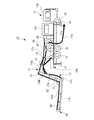
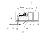
11 装置搭載車
11a 荷台
11b 車両運転室
11c 操作室
12 汚泥回収手段
13 タイヤ
14 転倒防止用アウトリガー
15 回収用伸縮ブーム手段
15a 主ブーム
15b 主アーム
15c テレスコアーム
15d 回収用伸縮ブーム
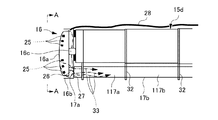
16 切削粉砕機
16a 回転刃体
16b 外側枠体
16c 油圧モータ
17 回収ホース
17a 吸込口
17b 吸引用配管
17c 吸引圧送用ホース
17d 最終ホース
17e 自在管継手
117 伸縮部
117a〜117e 摺動配管部
18 主ブームシリンダ
19 主アームシリンダ
21 角度調整用シリンダ
22 伸縮フレーム旋回用油圧モータ
23 脱着装置
23a、23b 連結片
23c ピン挿入穴
24 開口
25 切削刃
26 振り払い用刃
27 回収ホース挿入用開口
28 油圧ホース
29 油圧ホースリール
30 回収ホースリール
31 シール用ゴムパッキン
32 吊り金具
33 汚泥物の流れ
50 制御部
51 センサ
100 格納領域
S1、S2 隙間
自走式の装置搭載車と前記装置搭載車上に搭載された汚泥回収手段とよりなり、
前記汚泥回収手段が、
前記汚泥物を受容して切削粉砕する切削粉砕機と、
一端側に前記切削粉砕機を取り付け他端側が前記装置搭載車上に取り付けられて、前記装置搭載車上に伸縮、かつ折り畳み自在に配設された回収用伸縮ブーム手段と、
前記回収用伸縮ブーム手段に沿って配設され、内部に前記切削粉砕機で切削粉砕された前記汚泥物を通して所定の回収位置まで送るための回収ホースと、を備え、
前記回収用伸縮ブーム手段は、前記装置搭載車に対して左右及び上下並びに前後の各方向に旋回可能な主ブームと、前記主ブームの先端側に取り付けられた伸縮式のテレスコアームを備え、前記テレスコアームの先端側に前記切削粉砕機を取り付け、
前記回収用伸縮ブーム手段は、前記テレスコアームの先端と前記切削粉砕機との間に前記テレスコアームに対して左右方向に旋回可能な伸縮式の回収用伸縮ブームと、前記回収用伸縮ブームの旋回駆動を制御する伸縮ブーム旋回用油圧モータとを備える、
ことを特徴とする汚泥回収装置。
Claims (15)
- 水中の汚泥物を回収する汚泥回収装置であって、
自走式の装置搭載車と前記装置搭載車上に搭載された汚泥回収手段とよりなり、
前記汚泥回収手段が、
前記汚泥物を受容して切削粉砕する切削粉砕機と、
一端側に前記切削粉砕機を取り付け他端側が前記装置搭載車上に取り付けられて、前記装置搭載車上に伸縮、かつ折り畳み自在に配設された回収用伸縮ブーム手段と、
前記回収用伸縮ブーム手段に沿って配設され、内部に前記切削粉砕機で切削粉砕された前記汚泥物を通して所定の回収位置まで送るための回収ホースと、
を備える、ことを特徴とする汚泥回収装置。 - 前記装置搭載車は、転倒防止用アウトリガーを備える、ことを特徴とする請求項1に記載の汚泥回収装置。
- 前記装置搭載車は、前記装置搭載車又は前記汚泥回収手段が過負荷を受けた時に前記汚泥回収手段の動作を停止する安全装置を備える、ことを特徴とする請求項1又は請求項2に記載の汚泥回収装置。
- 前記回収用伸縮ブーム手段は、前記装置搭載車に対して左右及び上下並びに前後の各方向に旋回可能な主ブームと、前記主ブームの先端側に取り付けられた伸縮式のテレスコアームを備え、前記テレスコアームの先端側に前記切削粉砕機を取り付けてなる、ことを特徴とする請求項1から請求項3のいずれか1項に記載の汚泥回収装置。
- 前記回収用伸縮ブーム手段は、前記テレスコアームの先端と前記切削粉砕機との間に前記テレスコアームに対して左右方向に旋回可能な伸縮式の回収用伸縮ブームと、前記回収用伸縮ブームの旋回駆動を制御する伸縮ブーム旋回用油圧モータとを備える、ことを特徴とする請求項4に記載の汚泥回収装置。
- 前記回収用伸縮ブーム手段は、前記回収用伸縮ブームを前記テレスコアームに対して上下方向に揺動操作な可能な角度調整用シリンダを備える、ことを特徴とする請求項4又は請求項5に記載の汚泥回収装置。
- 前記切削粉砕機は、前記汚泥物を切削粉砕する回転する切削刃と、前記切削刃を回転させる油圧駆動手段とを備える、ことを特徴とする請求項1から請求項6のいずれか1項に記載の汚泥回収装置。
- 前記切削粉砕機の前記切削刃は正逆2方向に回転可能で、かつ前記切削粉砕機は前記回収ホースと前記回収ホースの吸込口との間に、前記吸込口前面に滞る前記汚泥物を払拭する振り払い用刃を備える、ことを特徴とする請求項7に記載の汚泥回収装置。
- 前記切削粉砕機は、前記装置搭載車上に配設された油圧ホース用リールと、前記油圧ホース用リールに巻回されて一端側が前記回収用伸縮ブーム手段に沿って前記油圧駆動手段まで導出された切削機用油圧ホースとを備える、ことを特徴とする請求項1から請求項7又は請求項8に記載の汚泥回収装置。
- 前記回収ホースは、前記回収用伸縮ブームと対応して複数本の摺動配管部でなる多段振り出し竿構造の伸縮部を有し、前記伸縮部の各伸縮繋ぎ目部分にシール用ゴムパッキンを設けてなる、ことを特徴とする請求項5に記載の汚泥回収装置。
- 切削機用油圧ホースは、前記回収用伸縮ブーム手段に沿って配設された繊維強化プラスチック製の保護管内を通して配設してなる、ことを特徴とする請求項9に記載の汚泥回収装置。
- 油圧ホース用リールは、前記回収用伸縮ブームの伸縮に連動して巻き出し・巻き取りを行う、ことを特徴とする請求項9又は請求項11に記載の汚泥回収装置。
- 前記装置搭載車は、休憩可能な操作室を備える、ことを特徴とする請求項1から請求項12のいずれか1項に記載の汚泥回収装置。
- 前記汚泥回収手段は、少なくとも水中に浸る部分に揮発性剤を塗布してなる、ことを特徴とする請求項1から請求項12のいずれか1項に記載の汚泥回収装置。
- 前記切削機用の油圧は、生分解性を有するバイオ油圧作動油を用いる、ことを特徴とする請求項1から請求項14のいずれか1項に記載の汚泥回収装置。
Priority Applications (1)
| Application Number | Priority Date | Filing Date | Title |
|---|---|---|---|
| JP2016077994A JP6035444B1 (ja) | 2016-04-08 | 2016-04-08 | 汚泥回収装置 |
Applications Claiming Priority (1)
| Application Number | Priority Date | Filing Date | Title |
|---|---|---|---|
| JP2016077994A JP6035444B1 (ja) | 2016-04-08 | 2016-04-08 | 汚泥回収装置 |
Publications (2)
| Publication Number | Publication Date |
|---|---|
| JP6035444B1 JP6035444B1 (ja) | 2016-11-30 |
| JP2017186843A true JP2017186843A (ja) | 2017-10-12 |
Family
ID=57419827
Family Applications (1)
| Application Number | Title | Priority Date | Filing Date |
|---|---|---|---|
| JP2016077994A Expired - Fee Related JP6035444B1 (ja) | 2016-04-08 | 2016-04-08 | 汚泥回収装置 |
Country Status (1)
| Country | Link |
|---|---|
| JP (1) | JP6035444B1 (ja) |
Cited By (1)
| Publication number | Priority date | Publication date | Assignee | Title |
|---|---|---|---|---|
| JP7696664B1 (ja) * | 2024-10-17 | 2025-06-23 | 株式会社川瀬工務店 | 無人走行式浚渫装置 |
Families Citing this family (1)
| Publication number | Priority date | Publication date | Assignee | Title |
|---|---|---|---|---|
| CN117385963A (zh) * | 2023-10-16 | 2024-01-12 | 安徽雷克环境科技有限公司 | 一种湖塘一日清设备 |
Citations (7)
| Publication number | Priority date | Publication date | Assignee | Title |
|---|---|---|---|---|
| JPH0350645U (ja) * | 1989-09-19 | 1991-05-16 | ||
| JPH08238437A (ja) * | 1995-03-03 | 1996-09-17 | Hayamizugumi:Kk | 汚泥回収装置 |
| JPH10137995A (ja) * | 1996-11-12 | 1998-05-26 | Amada Eng Center:Kk | 油圧ホース支持装置 |
| JP2000054424A (ja) * | 1998-08-12 | 2000-02-22 | Gesuido Maintenance Kyodo Kumiai | 大深度人孔用浚渫装置 |
| JP2010248907A (ja) * | 2004-09-22 | 2010-11-04 | Tokyo Metropolitan Government | 大深度人孔用浚渫バケット装置の表示装置及び該浚渫バケット装置の運転方法 |
| JP2015001127A (ja) * | 2013-06-17 | 2015-01-05 | 三橋 満 | 携帯式電動アースオーガー |
| JP2015147859A (ja) * | 2014-02-06 | 2015-08-20 | コスモ石油ルブリカンツ株式会社 | 油圧作動油組成物 |
-
2016
- 2016-04-08 JP JP2016077994A patent/JP6035444B1/ja not_active Expired - Fee Related
Patent Citations (7)
| Publication number | Priority date | Publication date | Assignee | Title |
|---|---|---|---|---|
| JPH0350645U (ja) * | 1989-09-19 | 1991-05-16 | ||
| JPH08238437A (ja) * | 1995-03-03 | 1996-09-17 | Hayamizugumi:Kk | 汚泥回収装置 |
| JPH10137995A (ja) * | 1996-11-12 | 1998-05-26 | Amada Eng Center:Kk | 油圧ホース支持装置 |
| JP2000054424A (ja) * | 1998-08-12 | 2000-02-22 | Gesuido Maintenance Kyodo Kumiai | 大深度人孔用浚渫装置 |
| JP2010248907A (ja) * | 2004-09-22 | 2010-11-04 | Tokyo Metropolitan Government | 大深度人孔用浚渫バケット装置の表示装置及び該浚渫バケット装置の運転方法 |
| JP2015001127A (ja) * | 2013-06-17 | 2015-01-05 | 三橋 満 | 携帯式電動アースオーガー |
| JP2015147859A (ja) * | 2014-02-06 | 2015-08-20 | コスモ石油ルブリカンツ株式会社 | 油圧作動油組成物 |
Cited By (1)
| Publication number | Priority date | Publication date | Assignee | Title |
|---|---|---|---|---|
| JP7696664B1 (ja) * | 2024-10-17 | 2025-06-23 | 株式会社川瀬工務店 | 無人走行式浚渫装置 |
Also Published As
| Publication number | Publication date |
|---|---|
| JP6035444B1 (ja) | 2016-11-30 |
Similar Documents
| Publication | Publication Date | Title |
|---|---|---|
| JP6095592B2 (ja) | 油圧ショベルの監視画像表示装置 | |
| JP2008133715A (ja) | 下水道網を清浄する可動ユニット | |
| JP6324934B2 (ja) | 散水アタッチメント、作業機械及び散水システム | |
| CA2940214A1 (en) | Vacuum unit and truck with air and water | |
| JP5232819B2 (ja) | 浚渫装置 | |
| JP6035444B1 (ja) | 汚泥回収装置 | |
| JP6663404B2 (ja) | 建設機械の排土装置 | |
| JP6236273B2 (ja) | 高所作業機能付車両 | |
| US20170144604A1 (en) | Control system for ladder and machine using the same | |
| JP2009263996A (ja) | 作業機械 | |
| KR101725973B1 (ko) | 준설 흡입과 배사 일원화 준설 장비 및 이를 이용한 준설 방법 | |
| JP2010180539A (ja) | 油圧式作業機の緊急脱出方法 | |
| JP2020139347A (ja) | 作業車の安全装置 | |
| KR102019780B1 (ko) | 작업기계 | |
| KR102287676B1 (ko) | 이동식 준설장치 | |
| JP2007247199A (ja) | 縦孔掘削ユニット、縦孔掘削サブシステム及び縦孔掘削システム | |
| JP6520297B2 (ja) | 軌陸車の遠隔操作装置置き忘れ警報システム | |
| JP2019171968A (ja) | 作業車両 | |
| JP3794513B2 (ja) | ケーソン内掘削装置 | |
| JP6392194B2 (ja) | 建設機械 | |
| JP2003074011A (ja) | 路面切削作業機 | |
| JP3910837B2 (ja) | 作業機の油圧配管構造 | |
| JP3794511B2 (ja) | ケーソン内掘削装置 | |
| JP6524015B2 (ja) | 防災用車両 | |
| JP4484606B2 (ja) | 油圧シリンダの圧力検出構造 |
Legal Events
| Date | Code | Title | Description |
|---|---|---|---|
| TRDD | Decision of grant or rejection written | ||
| A01 | Written decision to grant a patent or to grant a registration (utility model) |
Free format text: JAPANESE INTERMEDIATE CODE: A01 Effective date: 20161025 |
|
| A61 | First payment of annual fees (during grant procedure) |
Free format text: JAPANESE INTERMEDIATE CODE: A61 Effective date: 20161031 |
|
| R150 | Certificate of patent or registration of utility model |
Ref document number: 6035444 Country of ref document: JP Free format text: JAPANESE INTERMEDIATE CODE: R150 |
|
| R250 | Receipt of annual fees |
Free format text: JAPANESE INTERMEDIATE CODE: R250 |
|
| R250 | Receipt of annual fees |
Free format text: JAPANESE INTERMEDIATE CODE: R250 |
|
| R250 | Receipt of annual fees |
Free format text: JAPANESE INTERMEDIATE CODE: R250 |
|
| R250 | Receipt of annual fees |
Free format text: JAPANESE INTERMEDIATE CODE: R250 |
|
| LAPS | Cancellation because of no payment of annual fees |