JP2017190107A - Reservoir tank mounting structure and motorcycle - Google Patents
Reservoir tank mounting structure and motorcycle Download PDFInfo
- Publication number
- JP2017190107A JP2017190107A JP2016082319A JP2016082319A JP2017190107A JP 2017190107 A JP2017190107 A JP 2017190107A JP 2016082319 A JP2016082319 A JP 2016082319A JP 2016082319 A JP2016082319 A JP 2016082319A JP 2017190107 A JP2017190107 A JP 2017190107A
- Authority
- JP
- Japan
- Prior art keywords
- reservoir tank
- air cleaner
- master cylinder
- frame
- mounting structure
- Prior art date
- Legal status (The legal status is an assumption and is not a legal conclusion. Google has not performed a legal analysis and makes no representation as to the accuracy of the status listed.)
- Granted
Links
Images

Landscapes
- Valves And Accessory Devices For Braking Systems (AREA)
- Transmission Of Braking Force In Braking Systems (AREA)
Abstract
【課題】リザーバホースを短縮すること。【解決手段】ブレーキオイルを貯留するリザーバタンク(8)の取付構造は、ブレーキ操作に応じてブレーキ圧を発生させるマスタシリンダ(7)と、リザーバタンクとマスタシリンダとを接続するリザーバホース(80)と、車体フレーム(2)によって囲まれる空間内に配置されるエアクリーナ(5)と、を備える。車体フレームは、スイングアーム(40)を揺動可能に支持するピボットフレーム(26)と、ピボットフレームから後方に延びるリヤフレーム(25)とを有する。エアクリーナは、リヤフレームより下方に突出しており、マスタシリンダは、ピボットフレームの後方において、エアクリーナの下方に配置される。リザーバタンクは、リヤフレームの下方のエアクリーナに取り付けられる。【選択図】図2PROBLEM TO BE SOLVED: To shorten a reservoir hose. SOLUTION: A reservoir tank (8) for storing brake oil has a mounting structure of a master cylinder (7) that generates a brake pressure in response to a brake operation, and a reservoir hose (80) that connects the reservoir tank and the master cylinder. And an air cleaner (5) arranged in the space surrounded by the vehicle body frame (2). The vehicle body frame includes a pivot frame (26) that swingably supports the swing arm (40), and a rear frame (25) that extends rearward from the pivot frame. The air cleaner projects below the rear frame, and the master cylinder is located behind the pivot frame and below the air cleaner. The reservoir tank is attached to the air cleaner below the rear frame. [Selection diagram] Fig. 2
Description
本発明は、リザーバタンクの取付構造及び自動二輪車に関する。 The present invention relates to a reservoir tank mounting structure and a motorcycle.
従来より、自動二位輪車のブレーキシステムにおいては、前輪と後輪にそれぞれ独立したブレーキ装置(例えば、ディスクブレーキやドラムブレーキ)が設けられている。例えば、油圧式のブレーキ装置では、ブレーキレバー(又はブレーキペダル)とブレーキ装置との間に、ブレーキホースを介してマスタシリンダが接続されている(例えば、特許文献1参照)。運転者がブレーキ操作をすることにより、マスタシリンダで油圧が発生し、発生した油圧は、ブレーキホースを介してブレーキ装置に伝達される。その結果、ブレーキ装置が作動する。 2. Description of the Related Art Conventionally, in a brake system for a motorcycle, independent brake devices (for example, disc brakes and drum brakes) are provided for front wheels and rear wheels. For example, in a hydraulic brake device, a master cylinder is connected between a brake lever (or brake pedal) and the brake device via a brake hose (see, for example, Patent Document 1). When the driver performs a brake operation, hydraulic pressure is generated in the master cylinder, and the generated hydraulic pressure is transmitted to the brake device via the brake hose. As a result, the brake device operates.
また、マスタシリンダには、ブレーキオイルを貯留するリザーバタンクが接続されている。リザーバタンク内のブレーキオイルがマスタシリンダに供給されることにより、マスタシリンダにおいてオイル不足が解消されている。 A reservoir tank that stores brake oil is connected to the master cylinder. By supplying brake oil in the reservoir tank to the master cylinder, the shortage of oil is eliminated in the master cylinder.
ところで、自動二輪車のブレーキシステムでは、車体フレーム内のスペースの関係上、マスタシリンダやリザーバタンクの取付箇所に制約がある。特に、特許文献1では、マスタシリンダとリザーバタンクとが離れた箇所に設けられている。このため、マスタシリンダとリザーバタンクを接続する配管(リザーバホース)が長くなってしまうという問題がある。 By the way, in a motorcycle brake system, there is a restriction on the mounting position of the master cylinder and the reservoir tank due to the space in the vehicle body frame. In particular, in Patent Document 1, the master cylinder and the reservoir tank are provided at separate locations. For this reason, there exists a problem that piping (reservoir hose) which connects a master cylinder and a reservoir tank will become long.
本発明は係る点に鑑みてなされたものであり、リザーバホースを短縮することができるリザーバタンクの取付構造及び自動二輪車を提供することを目的とする。 SUMMARY An advantage of some aspects of the invention is that it provides a reservoir tank mounting structure and a motorcycle capable of shortening a reservoir hose.
本発明に係るリザーバタンクの取付構造は、ブレーキオイルを貯留するリザーバタンクの取付構造であって、ブレーキ操作に応じてブレーキ圧を発生させるマスタシリンダと、前記リザーバタンクと前記マスタシリンダとを接続するリザーバホースと、車体フレームによって囲まれる空間内に配置されるエアクリーナと、を備え、前記車体フレームは、スイングアームを揺動可能に支持するピボットフレームと、前記ピボットフレームから後方に延びるリヤフレームとを有し、前記エアクリーナは、前記リヤフレームより下方に突出しており、前記マスタシリンダは、前記ピボットフレームの後方において、前記エアクリーナの下方に配置され、前記リザーバタンクは、前記リヤフレームの下方の前記エアクリーナに取り付けられることを特徴とする。 A reservoir tank mounting structure according to the present invention is a reservoir tank mounting structure for storing brake oil, and connects a master cylinder that generates brake pressure in response to a brake operation, and the reservoir tank and the master cylinder. A reservoir hose and an air cleaner disposed in a space surrounded by the vehicle body frame, wherein the vehicle body frame includes a pivot frame that swingably supports a swing arm, and a rear frame that extends rearward from the pivot frame. The air cleaner protrudes downward from the rear frame, the master cylinder is disposed below the air cleaner behind the pivot frame, and the reservoir tank is disposed below the rear frame. Specially attached to To.
この構成によれば、ピボットフレームの後方において、リザーバタンクがエアクリーナの下側に取り付けられ、マスタシリンダがエアクリーナの下方に設けられる。これにより、リザーバタンクとマスタシリンダとを近づけて配置することができる。この結果、リザーバホースを短くすることができる。また、リザーバタンクがエアクリーナに取り付けられることで、車体フレームの振動が直接リザーバタンクに伝わるのを抑制することができる。 According to this configuration, the reservoir tank is attached to the lower side of the air cleaner and the master cylinder is provided below the air cleaner behind the pivot frame. Thereby, the reservoir tank and the master cylinder can be arranged close to each other. As a result, the reservoir hose can be shortened. Further, since the reservoir tank is attached to the air cleaner, it is possible to suppress the vibration of the vehicle body frame from being directly transmitted to the reservoir tank.
また、本発明に係る上記リザーバタンクの取付構造では、側面視において、前記マスタシリンダの軸方向が前記エアクリーナに向けられていることが好ましい。この構成によれば、マスタシリンダの先端がエアクリーナに近づけられることで、マスタシリンダとリザーバタンクを更に近づけることができる。 In the reservoir tank mounting structure according to the present invention, it is preferable that an axial direction of the master cylinder is directed to the air cleaner in a side view. According to this configuration, the master cylinder and the reservoir tank can be brought closer to each other by bringing the tip of the master cylinder closer to the air cleaner.
また、本発明に係る上記リザーバタンクの取付構造において、前記リザーバタンクは、前記マスタシリンダの中心軸より車幅方向内側に偏って配置されることが好ましい。この構成によれば、リザーバタンクがマスタシリンダより車幅方向外側に突出するのを防止することができ、外観性が向上する。 In the above-described reservoir tank mounting structure according to the present invention, it is preferable that the reservoir tank is disposed to be deviated inward in the vehicle width direction from the central axis of the master cylinder. According to this configuration, the reservoir tank can be prevented from protruding outward in the vehicle width direction from the master cylinder, and the appearance is improved.
また、本発明に係る上記リザーバタンクの取付構造において、前記エアクリーナの側面には、凹部が形成されており、前記リザーバタンクは、前記凹部に収容されることが好ましい。この構成によれば、リザーバタンクの突出量を抑えることができ、外観性が向上する。 In the reservoir tank mounting structure according to the present invention, it is preferable that a recess is formed on a side surface of the air cleaner, and the reservoir tank is accommodated in the recess. According to this configuration, the amount of protrusion of the reservoir tank can be suppressed, and the appearance is improved.
また、本発明に係る上記リザーバタンクの取付構造は、前記スイングアームの後端に設けられる後輪の前側を覆うフェンダを更に備え、前記フェンダは、前記リザーバタンクの後方に設けられ、前記リザーバタンクは、車幅方向において、前記フェンダと重なるように配置されることが好ましい。この構成によれば、車幅方向でリザーバタンクとフェンダが重なることで、後輪によって跳ね上げられる水や埃等がフェンダによって遮られるため、水や埃等がリザーバタンクに付着するのを防止することができる。 The reservoir tank mounting structure according to the present invention further includes a fender that covers a front side of a rear wheel provided at a rear end of the swing arm, and the fender is provided behind the reservoir tank. Is preferably arranged so as to overlap the fender in the vehicle width direction. According to this configuration, since the reservoir tank and the fender overlap in the vehicle width direction, water, dust, and the like splashed up by the rear wheels are blocked by the fender, so that water, dust, and the like are prevented from adhering to the reservoir tank. be able to.
また、本発明に係る自動二輪車は、上記リザーバタンクの取付構造を備えることが好ましい。 The motorcycle according to the present invention preferably includes the above-described reservoir tank mounting structure.
本発明によれば、マスタシリンダにリザーバタンクを近づけて配置することで、リザーバホースを短縮することができる。 According to the present invention, the reservoir hose can be shortened by arranging the reservoir tank close to the master cylinder.
以下、本発明の実施の形態について添付図面を参照して詳細に説明する。なお、以下においては、本発明に係るリザーバタンクの取付構造をダイヤモンド型のフレームを備えた自動二輪車に適用した例について説明するが、適用対象はこれに限定されることなく変更可能である。例えば、本発明に係るリザーバタンクの取付構造を、他のタイプのフレームを備えた自動二輪車や、バギータイプの自動三輪車等に適用してもよい。また、方向について、車両前方を矢印FR、車両後方を矢印RE、車両左側を矢印L、車両右側を矢印Rでそれぞれ示す。また、以下の各図では、説明の便宜上、一部の構成を省略している。特に、図1では、エンジン及び前輪、後輪を外形線のみで表している。 Hereinafter, embodiments of the present invention will be described in detail with reference to the accompanying drawings. In the following, an example in which the reservoir tank mounting structure according to the present invention is applied to a motorcycle equipped with a diamond-shaped frame will be described. However, the application target is not limited to this and can be changed. For example, the reservoir tank mounting structure according to the present invention may be applied to a motorcycle equipped with another type of frame, a buggy type motorcycle, or the like. Regarding the direction, the front of the vehicle is indicated by an arrow FR, the rear of the vehicle is indicated by an arrow RE, the left side of the vehicle is indicated by an arrow L, and the right side of the vehicle is indicated by an arrow R. In the following drawings, a part of the configuration is omitted for convenience of explanation. In particular, in FIG. 1, the engine, front wheels, and rear wheels are represented only by outlines.
図1を参照して、本実施の形態に係る自動二輪車の概略構成について説明する。図1は、本実施の形態に係るリザーバタンクの取付構造が適用される自動二輪車の概略側面図である。 With reference to FIG. 1, a schematic configuration of the motorcycle according to the present embodiment will be described. FIG. 1 is a schematic side view of a motorcycle to which a reservoir tank mounting structure according to the present embodiment is applied.
図1に示すように、本実施の形態に係る自動二輪車1は、鋼製又はアルミ合金製の車体フレーム2にエンジン3を懸架して構成される。車体フレーム2は、いわゆるダイヤモンド型のフレームであり、エンジン3を懸架することで、車両全体として剛性が得られるように構成されている。車体フレーム2は、複数のフレームを溶接等により結合して形成される。
As shown in FIG. 1, a motorcycle 1 according to the present embodiment is configured by suspending an engine 3 on a
具体的に車体フレーム2は、ヘッドパイプ20の上端から後下方に向かって延びるメインフレーム21と、ヘッドパイプ20の下端から後方に向かって延びるダウンフレーム22とを有している。メインフレーム21は、途中で左右に分岐してそれぞれが後下方に向かって延びている。ダウンフレーム22は、メインフレーム21の略中央部分に連結される。また、ダウンフレーム22の中央には、下方に向かって延びるハンガーフレーム23が連結されている。
Specifically, the
メインフレーム21の中央部分には、後方に向かって延びる左右一対のシートフレーム24が連結されている。シートフレーム24には、図示しないシートが支持される。また、メインフレーム21の下端には、シートフレーム24を支える左右一対のリヤフレーム25と、スイングアーム40を支持するピボットフレーム26とが連結されている。
A pair of left and
リヤフレーム25は、メインフレーム21の下端から後上方に向かって延び、シートフレーム24の後端に連結される。リヤフレーム25の略中央には、後下方に向かって二又状のブラケット25aが延びている。ブラケット25aの先端には、同乗者用のフットレスト41が設けられている。ピボットフレーム26は、メインフレーム21の下端から下方に向かって延びている。ピボットフレーム26の延在方向の中間部分には、スイングアーム40を揺動可能に支持するスイングアームピボット26aが形成されている。
The
このように構成される車体フレーム2では、シリンダヘッド30の前側がハンガーフレーム23によって支持され、クランクケース31の後側がピボットフレーム26に支持されている。これにより、エンジン3が車体フレーム2に懸架される。
In the
ヘッドパイプ20には、ステアリングシャフト(不図示)を介してフロントフォーク42が支持されている。ステアリングシャフトの上端にはハンドルバー43が設けられている。フロントフォーク42の下部には、前輪44が回転可能に支持されている。
A
前輪44には、ブレーキディスク(不図示)が設けられる一方、フロントフォーク42の下端には、ブレーキディスクを挟持するブレーキキャリパ(不図示)が設けられる。また、前輪44の上方は、フロントフェンダ45によって覆われている。
The
スイングアーム40は、スイングアームピボット26aから後方に向かって延びている。スイングアーム40と車体フレーム2(ピボットフレーム26)との間には、リヤサスペンション(不図示)が設けられている。スイングアーム40の後部には、後輪46が回転可能に支持されている。
The
後輪46には、ブレーキディスク(不図示)が設けられる一方、スイングアーム40の後端には、ブレーキディスクを挟持するブレーキキャリパ(不図示)が設けられている。また、後輪46の前側は、リヤインナフェンダ47(図2参照)によって覆われている。リヤインナフェンダ47は、スイングアーム40の上面に固定されている。
The
エンジン3の後上方には、エアクリーナ5が配置されている。エアクリーナ5は、外部から導入される空気をろ過してエンジン3内に送り込む役割を果たす。エアクリーナ5は、車体フレーム2によって囲まれる空間内に配置されている。具体的にエアクリーナ5は、シートフレーム24の下方において、左右一対のリヤフレーム25に挟み込まれるようにして配置されている。詳細は後述するが、エアクリーナ5の下半部は、リヤフレーム25より下方に突出している。エアクリーナ5は、吸気ダクト50を介してエンジン3の吸気ポート32に接続される。
An
ピボットフレーム26の後側には運転者の足を保護するヒールガード60が取り付けられている。ヒールガード60は、後方に向かって鋭角を成すように側面視略三角形状に形成されている。また、ヒールガード60は、周辺構成を固定するためのブラケットとしても機能する。
A
具体的にヒールガード60には、運転者用のフットレスト61、後輪用のブレーキペダル62、リヤブレーキ用のマスタシリンダ7等が取り付けられる。フットレスト61及びブレーキペダル62は、ヒールガード60の外面(車幅方向外側)に設けられている。マスタシリンダ7は、ヒールガード60の内面(車幅方向内側)に設けられている。ヒールガード60の周辺構成については後述する。
Specifically, a
ヒールガード60の上方には、ブレーキオイルを貯留するリザーバタンク8が設けられている。リザーバタンク8は、エアクリーナ5の下端に取り付けられている。マスタシリンダ7とリザーバタンク8は、リザーバホース80(図2参照)によって接続されている。
A reservoir tank 8 for storing brake oil is provided above the
ところで、自動二輪車において、リヤブレーキ用のマスタシリンダやリザーバタンクを取り付ける場合には、車体フレーム内のスペースの関係から、その取付位置に様々な制約が存在する。例えば、ペダル式の後輪ブレーキにあっては、ブレーキペダルの操作をマスタシリンダにダイレクトに伝えることが好ましい。このため、マスタシリンダはブレーキペダルの近傍に設けられることが多く、その取付位置は限られている。 By the way, in a motorcycle, when a master cylinder or a reservoir tank for a rear brake is attached, there are various restrictions on the attachment position due to the space in the vehicle body frame. For example, in a pedal-type rear wheel brake, it is preferable to directly transmit the operation of the brake pedal to the master cylinder. For this reason, the master cylinder is often provided in the vicinity of the brake pedal, and its mounting position is limited.
また、リザーバタンクを車体フレームに取り付ける場合、専用のブラケットが必要となり、部品点数増加の要因と成り得る。また、車両の振動が車体フレームを介してリザーバタンクに伝わることにより、リザーバタンク内のブレーキオイルに気泡(キャビテーション)が発生するおそれがある。 In addition, when the reservoir tank is attached to the vehicle body frame, a dedicated bracket is required, which may increase the number of parts. Further, when the vibration of the vehicle is transmitted to the reservoir tank through the vehicle body frame, there is a possibility that bubbles (cavitation) are generated in the brake oil in the reservoir tank.
この気泡がブレーキホース内に混入されると、マスタシリンダで発生する油圧を下流側のブレーキ装置(例えば、ブレーキキャリパ)に適切に伝達できない可能性がある。ゴム等の防振部材を介してリザーバタンクを車体フレームに取り付けることも考えられるが、結局、部品点数が増加することになる。 If these bubbles are mixed in the brake hose, there is a possibility that the hydraulic pressure generated in the master cylinder cannot be properly transmitted to the brake device (for example, brake caliper) on the downstream side. Although it is conceivable to attach the reservoir tank to the vehicle body frame via a vibration isolating member such as rubber, the number of parts will increase eventually.
また、リザーバタンクの取付位置によっては、マスタシリンダとリザーバタンクとの距離が離れてしまい、両者を接続するリザーバホースが長くなってしまうという問題もある。 Further, depending on the mounting position of the reservoir tank, there is a problem that the distance between the master cylinder and the reservoir tank is increased, and the reservoir hose connecting the both becomes long.
そこで、本実施の形態では、エアクリーナ5の一部をリヤフレーム25より下方に突出させ、エアクリーナ5の下部に直接リザーバタンク8を取り付けるようにした。エアクリーナ5は、所定の容積を有し、樹脂材料で形成されるため、車両の振動を減衰する効果がある。よって、エアクリーナ5にリザーバタンク8が直付けされることで、部品点数を増やすことなく、車両の振動がリザーバタンク8に伝わり難くなった。
Therefore, in the present embodiment, a part of the
また、エアクリーナ5をリヤフレーム25より下方に突出させることで、エアクリーナ5をピボットフレーム26に近づけて配置することが可能となった。上記したように、エアクリーナ5の下部にリザーバタンク8を取り付けることで、ピボットフレーム26の後方に設けられるマスタシリンダ7にリザーバタンク8を近付けることに成功した。この結果、リザーバホース80を短縮することが可能になった。
Further, by causing the
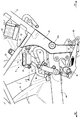
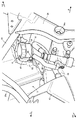
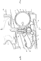
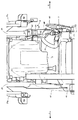
次に、図2から図5を参照して、リザーバタンクの取付構造及び後輪のブレーキシステムについて説明する。図2は、図1に示すリザーバタンク周辺の拡大図である。図3は、本実施の形態に係るリザーバタンク周辺の構成を右後方から見た斜視図である。図4は、図2に示すエアクリーナ及びリザーバタンクをX−X線に沿って切断した断面図である。図5は、本実施の形態に係るリザーバタンク周辺の構成を示す背面図である。なお、図3では、説明の便宜上、ヒールガードを省略している。 Next, the reservoir tank mounting structure and the rear wheel brake system will be described with reference to FIGS. FIG. 2 is an enlarged view around the reservoir tank shown in FIG. FIG. 3 is a perspective view of the configuration around the reservoir tank according to the present embodiment as viewed from the right rear. 4 is a cross-sectional view of the air cleaner and the reservoir tank shown in FIG. 2 cut along the line XX. FIG. 5 is a rear view showing the configuration around the reservoir tank according to the present embodiment. In FIG. 3, the heel guard is omitted for convenience of explanation.
図2から図4に示すように、エアクリーナ5は、シートフレーム24(図1参照)の下方空間に配置されている。エアクリーナ5は、例えば、プラスチック等の樹脂材料により、射出成型される。エアクリーナ5は、所定の容積を有する箱形状を有しており、下半部がリヤフレーム25より下方に突出している。
As shown in FIGS. 2 to 4, the
エアクリーナ5の右側面には、下端部において、車幅方向内側に窪んだ凹部51が形成されている。また、エアクリーナ5の外面と凹部51との境界部分には、車幅方向外側に突出するボス52が形成されている。ボス52には、リザーバタンク8を取り付けるためのネジ穴53が形成されている(図4参照)。
On the right side surface of the
リザーバタンク8は、例えば、プラスチック等の樹脂材料により、射出成形される。リザーバタンク8は、有底筒状のケース81とキャップ82とを有し、概して円筒形状を有している。ケース81の内部には、ブレーキオイルが貯留されており、ケース81の上方からキャップ82をねじ込むことにより、ケース81とキャップ82が一体化される。
The reservoir tank 8 is injection-molded by a resin material such as plastic. The reservoir tank 8 has a bottomed
ケース81の外面には、後方に向かって突出するフランジ部83が形成されている。フランジ部83には、ボルト84を通すための貫通口83aが形成されている(図4参照)。リザーバタンク8は、貫通口83aにボルト84を挿通し、ボルト84をボス52のネジ穴53にねじ込むことでエアクリーナ5に固定される。
A flange portion 83 that protrudes rearward is formed on the outer surface of the
また、リザーバタンク8には、キャップ82が不用意に取り外されるのを防止する規制プレート85が設けられる。規制プレート85は、例えば、金属板を折り曲げて形成される。具体的に規制プレート85は、フランジ部83の側面からリザーバタンク8の外形に沿って上方に向かって立ち上がり、キャップ82の上面より僅かに高い位置で径方向内側に折り曲げて形成される。規制プレート85の上端部分がキャップ82の上面に当接することで、キャップ82の移動が規制される。規制プレート85は、リザーバタンク8(フランジ部83)と一緒にエアクリーナ5(ボス52)にボルト84で締結される。
The reservoir tank 8 is provided with a regulating
エアクリーナ5の下方において、ピボットフレーム26の後方には、ヒールガード60を介して、マスタシリンダ7、フットレスト61及びブレーキペダル62が取り付けられている。マスタシリンダ7は、リザーバタンク8の直下で、上下方向に延びている。このとき、マスタシリンダ7の先端がリザーバタンク8に向けられている。すなわち、側面視において、マスタシリンダ7の軸方向がエアクリーナ5に向けられている。
Below the
マスタシリンダ7の下端には、ブレーキペダル62が軸支されている。ブレーキペダル62は、前方に向かって延びている。ブレーキペダル62の右側面には、車幅方向外側に突出するフットレスト61が設けられている。フットレスト61は、マスタシリンダ7の下端よりやや前側に位置している。また、フットレスト61は、ブレーキペダル62を貫通してヒールガード60に固定される。ブレーキペダル62は、フットレスト61を軸に揺動可能に構成される。
A
マスタシリンダ7の上端には、ブレーキホース70が接続されている。ブレーキホース70は、前方に向かって延び、ピボットフレーム26の手前でU字状に屈曲している。そして、ブレーキホース70は、スイングアーム40の上面に沿って後方に延び、後端のブレーキキャリパ(不図示)に接続される。
A
また、マスタシリンダ7の軸方向略中央には、後方に向かって配管接続口71が突出している。配管接続口71には、リザーバホース80の一端が接続される。リザーバホース80の他端は、リザーバタンク8(ケース81)の下面に接続される。リザーバホース80は、例えばゴム等の可撓性材料で形成されている。また、図2に示すように、リザーバホース80は、配管接続口71から前上方に向かってリザーバタンク8に延びており、側面視略S字状にカーブを成して配設されている。
In addition, a pipe connection port 71 protrudes toward the rear substantially at the center in the axial direction of the master cylinder 7. One end of a
このように構成される後輪46(図1参照)のブレーキシステムでは、運転者のブレーキ操作に応じてマスタシリンダ7にブレーキ圧が発生する。具体的には、運転者によってブレーキペダル62が踏み込まれると、ブレーキペダル62の先端がフットレスト61を中心に下方に向かって回動する。一方、ブレーキペダル62の後端は、上方に回動される。これにより、マスタシリンダ7のピストン(不図示)が上方に押し上げられ、マスタシリンダ7内で油圧が発生する。
In the brake system for the rear wheel 46 (see FIG. 1) configured as described above, brake pressure is generated in the master cylinder 7 in accordance with the driver's brake operation. Specifically, when the
発生した油圧は、ブレーキホース70を介してブレーキキャリパに伝達される。この結果、ブレーキキャリパが作動される。また、リザーバタンク8がマスタシリンダ7の上方に配置されることにより、エアがマスタシリンダ7側へ流れ込まず、ブレーキオイルのみが常時供給されている。このため、マスタシリンダ7のオイル不足が解消されている。
The generated hydraulic pressure is transmitted to the brake caliper via the
また、上記したように、本実施の形態では、エアクリーナ5に直接リザーバタンク8を取り付けている。このため、リザーバタンク8専用のブラケットを用意する必要がなく、部品点数を増やすことなくリザーバタンク8を固定することができる。また、リザーバタンク8がエアクリーナ5を介して固定されることで、車両の振動がリザーバタンク8に伝わり難くなっている。このため、リザーバタンク8内のブレーキオイルに気泡が発生するのを防止することができる。
Further, as described above, in this embodiment, the reservoir tank 8 is directly attached to the
また、エアクリーナ5にリザーバタンク8が取り付けられ、リザーバタンク8にゴム製のリザーバホース80が接続されることにより、ブレーキオイルが貯留されたリザーバタンク8をマスダンパの質量体として、リザーバホース80をダンパとして機能させることができる。これにより、エアクリーナ5の振動減衰効果を得ることも可能になっている。
Further, a reservoir tank 8 is attached to the
また、図4に示すように、車幅方向において、リザーバタンク8の一部がエアクリーナ5の凹部51に収容されるように配置されている。このため、車幅方向外側におけるリザーバタンク8の突出量を抑えることできる。よって、車両全体としての外観性が向上される。
Further, as shown in FIG. 4, the reservoir tank 8 is arranged so that a part of the reservoir tank 8 is accommodated in the recess 51 of the
また、図5に示すように、リザーバタンク8は、マスタシリンダ7より車幅方向内側に偏って配置されている。具体的には、リザーバタンク8の中心軸C1がマスタシリンダ7の中心軸C2より車幅方向内側に位置している。これにより、リザーバタンク8がマスタシリンダ7より車幅方向外側に突出するのを防止することができる。よって、車両全体としての外観性が更に向上される。 Further, as shown in FIG. 5, the reservoir tank 8 is arranged to be biased inward in the vehicle width direction from the master cylinder 7. Specifically, the central axis C1 of the reservoir tank 8 is located on the inner side in the vehicle width direction than the central axis C2 of the master cylinder 7. Thereby, it is possible to prevent the reservoir tank 8 from protruding outward in the vehicle width direction from the master cylinder 7. Therefore, the appearance of the entire vehicle is further improved.
また、図5に示すように、リザーバタンク8の後方にリヤインナフェンダ47が設けられている。リヤインナフェンダ47は、背面視において、スイングアーム40の左右幅と略同一の幅を有している。この場合、リザーバタンク8は、車幅方向においてリヤインナフェンダ47と重なるように配置されている。これにより、例えば、走行中に後輪46によって跳ね上げられる水や埃等がリヤインナフェンダ47によって遮られるため、水や埃等がリザーバタンク8に付着するのを防止することができる。
Further, as shown in FIG. 5, a rear inner fender 47 is provided behind the reservoir tank 8. The rear inner fender 47 has substantially the same width as the left and right width of the
以上説明したように、本実施の形態では、ピボットフレーム26の後方において、リザーバタンク8がエアクリーナ5の下側に取り付けられ、マスタシリンダ7がエアクリーナ5の下方に設けられる。これにより、リザーバタンク8とマスタシリンダ7とを近づけて配置することができる。特に、側面視において、マスタシリンダ7の軸方向がエアクリーナ5に向けられていることで、マスタシリンダ7の先端がエアクリーナ5に近づけられ、マスタシリンダ7とリザーバタンク8を更に近づけることができる。これらにより、リザーバタンク8とマスタシリンダ7とを接続するリザーバホース80の長さを短くすることができる。また、リザーバタンク8がエアクリーナ5に取り付けられることで、車体フレーム2の振動が直接リザーバタンク8に伝わるのを抑制することができる。
As described above, in the present embodiment, the reservoir tank 8 is attached to the lower side of the
なお、本発明は上記実施の形態に限定されず、種々変更して実施することが可能である。上記実施の形態において、添付図面に図示されている大きさや形状などについては、これに限定されず、本発明の効果を発揮する範囲内で適宜変更することが可能である。その他、本発明の目的の範囲を逸脱しない限りにおいて適宜変更して実施することが可能である。 In addition, this invention is not limited to the said embodiment, It can change and implement variously. In the above-described embodiment, the size, shape, and the like illustrated in the accompanying drawings are not limited to this, and can be appropriately changed within a range in which the effect of the present invention is exhibited. In addition, various modifications can be made without departing from the scope of the object of the present invention.
例えば、上記した実施の形態においては、ディスク式のブレーキ装置を例にして説明したが、これに限定されない。例えば、ドラム式のブレーキ装置であってもよい。 For example, in the above-described embodiment, the disk type brake device has been described as an example, but the present invention is not limited to this. For example, a drum type brake device may be used.
また、上記した実施の形態において、エアクリーナ5にリザーバタンク8が直付けされる構成としたが、この構成に限定されない。リザーバタンク8は、ゴム等の防振部材を介してエアクリーナ5に取り付けられてもよい。これにより、更なる防振効果を得ることができる。
In the above-described embodiment, the reservoir tank 8 is directly attached to the
また、上記した実施の形態において、エアクリーナ5の凹部51にリザーバタンク8の一部が収容される構成としたが、この構成に限定されない。リザーバタンク8全体が凹部51に収容されるように構成してもよい。
In the above-described embodiment, a part of the reservoir tank 8 is accommodated in the recess 51 of the
以上説明したように、本発明は、リザーバホースを短縮することができるという効果を有し、特に、リザーバタンクの取付構造及び自動二輪車に有用である。 As described above, the present invention has an effect that the reservoir hose can be shortened, and is particularly useful for a reservoir tank mounting structure and a motorcycle.
1 自動二輪車
2 車体フレーム
25 リヤフレーム
26 ピボットフレーム
40 スイングアーム
46 後輪
47 リヤインナフェンダ(フェンダ)
5 エアクリーナ
51 凹部
7 マスタシリンダ
8 リザーバタンク
80 リザーバホース
1
5 Air cleaner 51 Recess 7 Master cylinder 8
Claims (6)
ブレーキ操作に応じてブレーキ圧を発生させるマスタシリンダと、
前記リザーバタンクと前記マスタシリンダとを接続するリザーバホースと、
車体フレームによって囲まれる空間内に配置されるエアクリーナと、を備え、
前記車体フレームは、スイングアームを揺動可能に支持するピボットフレームと、前記ピボットフレームから後方に延びるリヤフレームとを有し、
前記エアクリーナは、前記リヤフレームより下方に突出しており、
前記マスタシリンダは、前記ピボットフレームの後方において、前記エアクリーナの下方に配置され、
前記リザーバタンクは、前記リヤフレームの下方の前記エアクリーナに取り付けられることを特徴とするリザーバタンクの取付構造。 A reservoir tank mounting structure for storing brake oil,
A master cylinder that generates brake pressure in response to brake operation;
A reservoir hose connecting the reservoir tank and the master cylinder;
An air cleaner disposed in a space surrounded by the body frame,
The vehicle body frame includes a pivot frame that swingably supports a swing arm, and a rear frame that extends rearward from the pivot frame.
The air cleaner protrudes downward from the rear frame;
The master cylinder is disposed below the air cleaner behind the pivot frame,
The reservoir tank mounting structure, wherein the reservoir tank is mounted on the air cleaner below the rear frame.
前記リザーバタンクは、前記凹部に収容されることを特徴とする請求項1から請求項3のいずれかに記載のリザーバタンクの取付構造。 A concave portion is formed on a side surface of the air cleaner,
The reservoir tank mounting structure according to any one of claims 1 to 3, wherein the reservoir tank is accommodated in the recess.
前記フェンダは、前記リザーバタンクの後方に設けられ、
前記リザーバタンクは、車幅方向において、前記フェンダと重なるように配置されることを特徴とする請求項1から請求項4のいずれかに記載のリザーバタンクの取付構造。 A fender that covers a front side of a rear wheel provided at a rear end of the swing arm;
The fender is provided behind the reservoir tank,
The reservoir tank mounting structure according to any one of claims 1 to 4, wherein the reservoir tank is disposed so as to overlap the fender in a vehicle width direction.
Priority Applications (1)
| Application Number | Priority Date | Filing Date | Title |
|---|---|---|---|
| JP2016082319A JP6642227B2 (en) | 2016-04-15 | 2016-04-15 | Mounting structure of reservoir tank and motorcycle |
Applications Claiming Priority (1)
| Application Number | Priority Date | Filing Date | Title |
|---|---|---|---|
| JP2016082319A JP6642227B2 (en) | 2016-04-15 | 2016-04-15 | Mounting structure of reservoir tank and motorcycle |
Publications (2)
| Publication Number | Publication Date |
|---|---|
| JP2017190107A true JP2017190107A (en) | 2017-10-19 |
| JP6642227B2 JP6642227B2 (en) | 2020-02-05 |
Family
ID=60086119
Family Applications (1)
| Application Number | Title | Priority Date | Filing Date |
|---|---|---|---|
| JP2016082319A Active JP6642227B2 (en) | 2016-04-15 | 2016-04-15 | Mounting structure of reservoir tank and motorcycle |
Country Status (1)
| Country | Link |
|---|---|
| JP (1) | JP6642227B2 (en) |
Citations (2)
| Publication number | Priority date | Publication date | Assignee | Title |
|---|---|---|---|---|
| JPS6261787U (en) * | 1985-10-09 | 1987-04-16 | ||
| JPH0867283A (en) * | 1994-08-31 | 1996-03-12 | Suzuki Motor Corp | Center structure of motorcycle body |
-
2016
- 2016-04-15 JP JP2016082319A patent/JP6642227B2/en active Active
Patent Citations (2)
| Publication number | Priority date | Publication date | Assignee | Title |
|---|---|---|---|---|
| JPS6261787U (en) * | 1985-10-09 | 1987-04-16 | ||
| JPH0867283A (en) * | 1994-08-31 | 1996-03-12 | Suzuki Motor Corp | Center structure of motorcycle body |
Also Published As
| Publication number | Publication date |
|---|---|
| JP6642227B2 (en) | 2020-02-05 |
Similar Documents
| Publication | Publication Date | Title |
|---|---|---|
| JP4306442B2 (en) | Motorcycle with anti-lock brake device | |
| JP4705938B2 (en) | Saddle-type vehicle with rear master cylinder | |
| JP5887241B2 (en) | Interlocking brake device for motorcycles | |
| JP6077784B2 (en) | Clamp structure for motorcycle rope | |
| CN105189270B (en) | Support structure of rear part of motorcycle | |
| JP2017047711A (en) | Sensor support structure and motorcycle | |
| JP5864878B2 (en) | Motorcycle | |
| JPWO2017169093A1 (en) | Reflector mounting structure for saddle-ride type vehicles | |
| JP2014069696A (en) | Motorcycle | |
| JP7030081B2 (en) | Front fork undercarriage of saddle-riding vehicle | |
| JP5789392B2 (en) | Motorcycle | |
| JP4559165B2 (en) | Saddle type vehicle fuel tank mounting structure | |
| JP7497249B2 (en) | Brake control device for human-powered vehicle and human-powered vehicle | |
| US20170274955A1 (en) | Saddle-riding-type vehicle cable support structure | |
| JP4727358B2 (en) | Brake piping structure of motorcycle | |
| JP6642227B2 (en) | Mounting structure of reservoir tank and motorcycle | |
| JP5101231B2 (en) | Saddle riding vehicle | |
| JP6894357B2 (en) | Brake piping structure for saddle-mounted vehicles | |
| JP5021971B2 (en) | Motorcycle front fender | |
| JP6076842B2 (en) | Support structure for rear parts of motorcycle | |
| JP6832821B2 (en) | Component support structure for saddle-mounted vehicles | |
| JP5606082B2 (en) | Vehicle blinker device | |
| JP3157690U (en) | Saddle riding vehicle | |
| JP2021098473A (en) | Saddle-riding type vehicle | |
| JP7083041B2 (en) | Wheel speed sensor mounting structure |
Legal Events
| Date | Code | Title | Description |
|---|---|---|---|
| A621 | Written request for application examination |
Free format text: JAPANESE INTERMEDIATE CODE: A621 Effective date: 20181116 |
|
| A977 | Report on retrieval |
Free format text: JAPANESE INTERMEDIATE CODE: A971007 Effective date: 20191120 |
|
| TRDD | Decision of grant or rejection written | ||
| A01 | Written decision to grant a patent or to grant a registration (utility model) |
Free format text: JAPANESE INTERMEDIATE CODE: A01 Effective date: 20191203 |
|
| A61 | First payment of annual fees (during grant procedure) |
Free format text: JAPANESE INTERMEDIATE CODE: A61 Effective date: 20191216 |
|
| R151 | Written notification of patent or utility model registration |
Ref document number: 6642227 Country of ref document: JP Free format text: JAPANESE INTERMEDIATE CODE: R151 |