JP2017190516A - Metal particle manufacturing method and metal particle manufacturing apparatus - Google Patents
Metal particle manufacturing method and metal particle manufacturing apparatus Download PDFInfo
- Publication number
- JP2017190516A JP2017190516A JP2016082337A JP2016082337A JP2017190516A JP 2017190516 A JP2017190516 A JP 2017190516A JP 2016082337 A JP2016082337 A JP 2016082337A JP 2016082337 A JP2016082337 A JP 2016082337A JP 2017190516 A JP2017190516 A JP 2017190516A
- Authority
- JP
- Japan
- Prior art keywords
- particles
- magnetic field
- metal
- molten metal
- electromagnet
- Prior art date
- Legal status (The legal status is an assumption and is not a legal conclusion. Google has not performed a legal analysis and makes no representation as to the accuracy of the status listed.)
- Pending
Links
Images

Landscapes
- Manufacture Of Metal Powder And Suspensions Thereof (AREA)
Abstract
【課題】落下速度が速すぎて粒子同士が衝突することがなく、へこみ及び欠けが無くて品質の良い金属粒子を高収率で製造することができる金属粒子の製造方法及び装置を提供する。【解決手段】溶融金属から金属粒子130を製造するに際し、圧電素子107にパルス圧力を発生させ、このパルス圧力によるプランジャ106の上下移動動作により、パルス圧力を、保持容器91内に保持した溶融金属に伝達し、パルス圧力が伝達された溶融金属に臨界変位以上の変位が発生して、保持容器に設けられたノズル104から溶融金属を、回収筒113内の不活性ガス雰囲気中に1個ずつ単分散粒子130として吐出して球形化し、回収筒の外部から電磁石112により交流磁場を回収筒内に発生させ、回収筒内に吐出された単分散粒子に、上向きに磁気体積力を発現させて、単分散粒子の落下速度を低減させつつ球形化した単分散粒子を回収する。【選択図】 図1Disclosed is a metal particle manufacturing method and apparatus capable of manufacturing metal particles of high quality without dropping and chipping without causing collision of particles due to too high a falling speed and high quality. In manufacturing metal particles from molten metal, a pulse pressure is generated in a piezoelectric element, and a molten metal in which a pulse pressure is held in a holding container by a vertically moving operation of a plunger by the pulse pressure. The molten metal to which the pulse pressure has been transmitted is displaced beyond the critical displacement, and the molten metal is supplied from the nozzle 104 provided in the holding container one by one into the inert gas atmosphere in the recovery cylinder 113. The particles are discharged as monodisperse particles 130 to form a sphere, and an alternating magnetic field is generated in the collection cylinder from the outside of the collection cylinder by the electromagnet 112. The monodisperse particles discharged into the collection cylinder are caused to express a magnetic volume force upward. The spherical monodisperse particles are recovered while reducing the falling speed of the monodisperse particles. [Selection] Figure 1
Description
本発明は、ノズルヘッドから溶融金属材料を吐出し、電磁石を用いた回収部で金属粒子を回収して金属粒子を製造する金属粒子の製造方法、及び、金属粒子の製造装置に関する。 The present invention relates to a metal particle manufacturing method and a metal particle manufacturing apparatus that discharges a molten metal material from a nozzle head and recovers metal particles in a recovery unit using an electromagnet to manufacture metal particles.
形状の揃った均一な粒子は、その材質を問わず、電気製品をはじめとする様々な科学技術分野で広く用いられ、その需要は拡大の一途である。例えば、ゾルゲル法にて製造される二酸化珪素の均一粒子は、液晶パネルにおいて、液晶を封入するガラス板の間隔を精度良く確保する手段として広く用いられている。 Regardless of the material, uniform particles with uniform shapes are widely used in various science and technology fields including electrical products, and the demand for the particles is expanding. For example, uniform particles of silicon dioxide produced by a sol-gel method are widely used in liquid crystal panels as means for accurately ensuring the interval between glass plates that enclose liquid crystals.
また、半導体ICパッケージの回路基板への接続のため、その電極部分にはんだ粒子が用いられている。このはんだ粒子は、格子状電極配置の半導体ICパッケージであるBG A(ボールグリッドアレイ)パッケージに使用されている。BGAパッケージの端子が0.3〜1.0mmピッチのものが多く普及しており、それに伴い、粒子径200〜800μmのBGAボールが広く使用されている。 Also, solder particles are used for the electrode portions for connection to the circuit board of the semiconductor IC package. The solder particles are used in a BGA (ball grid array) package, which is a semiconductor IC package having a grid electrode arrangement. Many BGA package terminals having a pitch of 0.3 to 1.0 mm are widely used, and accordingly, BGA balls having a particle diameter of 200 to 800 μm are widely used.
はんだ粒子において、へこみ及び欠けがないことは非常に重要なことである。例えば、はんだ粒子をBGAパッケージに実装する装置では、はんだ粒子を連続的に供給するために、停滞することなく転がることが求められるからである。もし、はんだ粒子の転がりが悪いと、装置の途中ではんだ粒子の供給が止まるので、この供給部分の調整などが頻繁に必要となり、生産効率を著しく低下させる。また、はんだ粒子をBGAパッケージに高精度で実装する方法として、BGAパッケージに合わせて高精度に配置したノズル部分を真空に引き、この部分に、はんだ粒子を吸着させ、所定の位置に配列する方法がある。この際に、はんだ粒子の表面のへこみ又は欠けが多いと吸着できず、はんだ粒子が搭載されない端子ができ、BGAパッケージそのものが不良となる。 It is very important that the solder particles are free of dents and chips. For example, an apparatus for mounting solder particles on a BGA package is required to roll without stagnation in order to continuously supply solder particles. If the rolling of the solder particles is poor, the supply of the solder particles is stopped in the middle of the apparatus. Therefore, it is necessary to frequently adjust the supply portion, and the production efficiency is remarkably reduced. Also, as a method of mounting solder particles on a BGA package with high accuracy, a nozzle portion arranged with high accuracy in accordance with the BGA package is evacuated, and solder particles are adsorbed on this portion and arranged at a predetermined position. There is. At this time, if there are a lot of dents or chips on the surface of the solder particles, they cannot be adsorbed, a terminal on which no solder particles are mounted is formed, and the BGA package itself becomes defective.
このはんだ粒子を製造する手段としては、るつぼ内の溶湯に圧力と振動とを付与して、前記るつぼの底部に設けたオリフィスから溶湯を押出し、前記オリフィスから滴下した溶湯を急冷凝固させて、はんだ粒子を製造する方法が、均一液滴噴霧法と呼ばれ、提案されている(例えば特許文献1参照)。図10は、特許文献1に記載された従来の均一液滴噴霧法を示す図である。
As means for producing the solder particles, pressure and vibration are applied to the molten metal in the crucible, the molten metal is pushed out from the orifice provided at the bottom of the crucible, and the molten metal dropped from the orifice is rapidly cooled and solidified, thereby A method for producing particles is called a uniform droplet spraying method and has been proposed (see, for example, Patent Document 1). FIG. 10 is a diagram showing a conventional uniform droplet spraying method described in
ここで、図10を用いて、上述の均一液滴噴霧装置を、より具体的に説明する。ピエゾ素子1で振動を発生させ、振動棒3を介して、溶湯4に振動が伝わる。溶解チャンバー5は、ガス供給口2よりガスが供給されて加圧された状態になっている。ガス圧力によって溶解チャンバー5のオリフィス6から押し出された溶湯4は、振動が与えられているので一定の間隔で分断され、液滴8が形成される。電極板7では、電極板7と溶湯4との間に電位を与えており、これによって、液滴8を同一電荷に帯電させて、液滴8同士が接することを防止している。これらの液滴8は、チャンバー9内を落下中に、液滴8自身の表面張力によって球状化され、ガス雰囲気を飛行中に冷却され、凝固する。
Here, the above-described uniform droplet spraying apparatus will be described more specifically with reference to FIG. A vibration is generated by the
チャンバー9内には、ガス供給口11より、不活性ガスが供給されており、液滴8の酸化を防止している。また、チャンバー9内の圧力は、溶解チャンバー5中より低くしてある。最終的には、球状凝固体10として、チャンバー9の底部に回収される。
An inert gas is supplied from the
しかしながら、前記従来の構成では、不活性ガス中で吐出した金属粒子の落下速度が速すぎて粒子同士が衝突してしまい、品質の悪い粒子(へこみ又は欠けなどが発生)が形成され、製造歩留りが悪いという課題を有している。 However, in the conventional configuration, the falling speed of the metal particles discharged in the inert gas collides with each other, resulting in the formation of poor quality particles (such as dents or chips), and the production yield. Has the problem of being bad.
本発明は、前記従来の課題を解決するもので、落下速度が速すぎて粒子同士が衝突することがなく、へこみ及び欠けが無くて品質の良い金属粒子を高収率で製造することができる金属粒子の製造方法及び装置を提供することを目的とする。 The present invention solves the above-mentioned conventional problems, and the drop speed is too high so that the particles do not collide with each other, and there is no dent and chipping, and high quality metal particles can be produced in a high yield. It aims at providing the manufacturing method and apparatus of a metal particle.
上記目的を達成するために、本発明の1つの態様にかかる金属粒子の製造方法は、溶融金属から金属粒子を製造するに際し、
圧電素子にパルス圧力を発生させ、
このパルス圧力によるプランジャの上下移動動作により、前記パルス圧力を、保持容器内に保持した前記溶融金属に伝達し、
前記パルス圧力が伝達された前記溶融金属に臨界変位以上の変位が発生して、前記保持容器に設けられたノズルから前記溶融金属を、回収筒内の不活性ガス雰囲気中に1個ずつ単分散粒子として吐出して球形化し、
前記回収筒の外部から電磁石により交流磁場を前記回収筒内に発生させ、前記回収筒内に吐出された前記単分散粒子に、上向きに磁気体積力を発現させて、前記単分散粒子の落下速度を低減させつつ前記球形化した単分散粒子を回収する。
In order to achieve the above object, a method for producing metal particles according to one aspect of the present invention, when producing metal particles from molten metal,
Generate a pulse pressure on the piezoelectric element,
By the vertical movement operation of the plunger by this pulse pressure, the pulse pressure is transmitted to the molten metal held in a holding container,
Displacement exceeding the critical displacement occurs in the molten metal to which the pulse pressure has been transmitted, and the molten metal is monodispersed one by one in an inert gas atmosphere in a collection cylinder from a nozzle provided in the holding container. Discharged as particles and spheroidized,
An alternating magnetic field is generated in the recovery cylinder by an electromagnet from the outside of the recovery cylinder, and the monodisperse particles discharged in the recovery cylinder are caused to express a magnetic volume force upward, and the falling speed of the monodisperse particles The spheroidized monodisperse particles are recovered while reducing the above.
以上のように、本発明の前記態様によれば、落下速度が速すぎて粒子同士が衝突することがなく、へこみ及び欠けが無くて品質の良い金属粒子を高収率で製造することができる。 As described above, according to the above aspect of the present invention, the falling speed is too high so that the particles do not collide with each other, and there are no dents and chips, so that high quality metal particles can be produced in a high yield. .
以下、本発明の実施の形態について、図面を参照しながら説明する。 Hereinafter, embodiments of the present invention will be described with reference to the drawings.
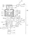
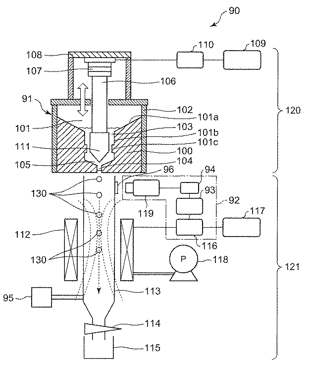
図1は、本発明の実施の形態における金属粒子の製造方法に用いられる金属粒子製造装置90の断面図である。この金属粒子製造装置90は、溶融した金属を吐出する吐出部120と、吐出部120から吐出した金属粒子130を回収する回収部121とを備えて、溶融金属から金属粒子を製造する。金属粒子の一例としては、粒子径200〜800μmの金属粒子である。
FIG. 1 is a cross-sectional view of a metal
まずは、金属粒子を吐出する吐出部120について説明する。
First, the
(吐出部120)
一例として、吐出部120はノズルヘッド100で構成される。ノズルヘッド100には、溶融金属供給室101と、圧力室105と、ノズル104と、吐出力付与装置の一例としての圧電素子107とプランジャ106とを備える。
(Discharge unit 120)
As an example, the
溶融金属供給室101は、素材となる金属材料を溶融金属として蓄える保持容器91内に形成する。保持容器91の供給室101の周囲には、加熱機構102が備えられ、供給室101内の金属材料をその融点以上に加熱して溶融させて溶融金属として保持する。供給室101の底面101aは、漏斗状となっており、底面101aの中央に凹部101bあり、凹部101bの下端は圧力室105に連通して、供給室101から圧力室105に、溶融した金属材料103を供給可能とする。溶融した金属材料103の例としては、はんだ材料であって、SnAgBiInCuを主成分とする合金が例示できる。
圧力室105の下端にノズル104を配置して圧力室105がノズル104に連通し、溶融した金属材料103を圧力室105から下方に所定の圧力で送り、ノズル104から下方に吐出可能とする。
The molten
The
プランジャ106は、供給室101を上下方向に貫通して、下端の先端部111が、供給室101の凹部101bと圧力室105との中で上下移動可能に配置される。凹部101bの下端の側面全周には凸部が突出形成されて小径部101cを構成する。プランジャ106の先端部111は尖塔状に加工が施されて、先端部111と小径部101cとにより、小径部101cよりも上側の供給室101と、小径部101cよりも下側の圧力室105とを仕切って、圧力室105内に供給された、溶融した金属材料103に加圧できるようにしている。よって、プランジャ106の先端部111が圧力室105内で上下移動することにより、凹部101bから小径部101cを介して圧力室105内に、溶融した金属材料103を供給可能で、かつ、圧力室105内に供給された金属材料103に対して、ノズル104から吐出するための圧力を生成可能とする。
The
また、このプランジャ106の上端は、推力を発生させる圧電素子107と接続されており、プランジャ106は、圧電素子107の推力を圧力室105に伝達する作用を担う。圧電素子107は、固定具108により供給室101の上部に固定されている。
The upper end of the
また、圧電素子107は、外部電源109と、ファンクションジェネレータ110と、電気的に接続され、外部電源109によりファンクションジェネレータ110を介して駆動することができる。ファンクションジェネレータ110において所定周波数の矩形波の電圧を発生させ、ファンクションジェネレータ110から圧電素子107に矩形波の電圧を印加し、所定周波数でかつ所定振幅の振動を圧電素子107に発生させる。その結果、圧電素子107と実質的に一体構造のプランジャ106を同じ周波数のパルスで保持容器91に対して上下方向に振動させ、プランジャ106の先端部側で接触している圧力室105内の、溶融した金属材料103にパルス圧力波を発生させる。
The
これにより、圧電素子107が、図1における下方に所定の変位量以上変位する(臨界変位以上に変位する)と、プランジャ106を介して圧力室105内の溶融した金属材料103をノズル104から液滴状にして吐出する。この吐出は、パルス圧力波の1周期に1回ずつ行われる。ここで、圧電素子107の臨界変位とは、溶融金属(溶融した金属材料103)に発生させる臨界変位のことであり、圧力室105内の溶融した金属材料103がノズル104から液滴状に吐出する程度の変位を意味する。例えば、粒子径200〜800μmの金属粒子を製造するとき、ノズル104の内径を160〜640μmとすると、所定周波数は10〜1000Hzであり、所定振幅は0.5〜170μm(変位量)である。なお、ノズル104の内径、圧電素子107の変位の周波数又は振幅も特に限定的ではなく、対象とする金属材料の種類、金属粒子の粒子径、又は、必要とする製造速度などに応じて、適宜選択すればよい。
Thereby, when the
(回収部121)
次に、金属粒子製造装置90を構成する回収部121について説明する。
(Recovery unit 121)
Next, the collection |
吐出部120を構成するノズル104の下部には、吐出される金属粒子130を捕捉するための回収部121が設けられる。回収部121は、電磁石112と、不活性ガスが供給される円筒状の回収筒113と、ゲートバルブ114と、回収部材の一例としての金属粒子回収ボックス115とを備える。よって、この回収部121の上端から、例えば、30cm以内に電磁石112を回収部121の外部に有する。電磁石112の下方でかつ回収筒113の下端には、回収筒113内に吐出された後、回収筒113内で冷却された金属粒子130に対して開閉可能なゲートバルブ114が配置されている。ゲートバルブ114のさらに下方には、ゲートバルブ114が開いたときゲートバルブ114を通過して落下する金属粒子130を回収する金属粒子回収ボックス115が接続されている。
A
ノズル104から回収筒113内に吐出された、溶融した金属材料103は、その表面張力により球形となり、回収筒113内の気体中にて冷却されて球形成がなされる。このとき、表面の酸化を抑制するために、不活性ガス供給装置95から回収筒113内に窒素等の不活性ガスが下から上向きに微少流量で供給されて、回収筒113内に窒素等の不活性ガス雰囲気を形成する。このように構成することにより、回収筒113内の窒素等の不活性ガス雰囲気中へ金属材料103が吐出されかつ冷却されることが望ましい。
The
また、電磁石112には、外部電源117と、ファンクションジェネレータ116とを用いて矩形波の交流電圧を加えている。電磁石112は、回収筒113の外周に配置されて、時間的に磁場方向が変わる交流磁場を発生させる円筒の電磁石であり、磁場方向と回収筒113の上下方向沿いの軸方向とが平行になるよう設置されている。時間的に磁場方向が変わる交流磁場とは、例えば、ある磁場強度で数msの間に百回〜数百回程度、磁場の正負を反転させるような交流磁場を意味している。交流電圧、磁場強度、時間、及び、反転回数等は、金属の種類又は金属粒子の粒径などにより異なっている。なお、圧電素子107に発生させる周波数と磁場の正負の反転回数との間に関係性を持たせて、例えば、磁場の正負を反転回数は、圧電素子107に発生させる周波数の±10%の範囲内とすれば、金属粒子130の落下速度がより制御しやすい場合もある。
In addition, a rectangular wave AC voltage is applied to the
吐出された金属材料103が金属粒子130として落下するときの落下速度を撮像装置例えば高速度カメラ119又はストロボカメラを用いて計測(算出)し、計測結果をファンクションジェネレータ116にフィードバックすることで、電磁石112の中心部での磁場の正負を制御して磁場の方向を制御し、金属粒子130に対して交流磁場を発生させて、磁気体積力を発現させて落下速度を減少させている。このフィードバックは、例えば以下のようにして行うことができる。
An electromagnet is obtained by measuring (calculating) the falling speed when the discharged
最初に、予め決められた初期条件下で、電磁石112の中心部での磁場の正負を制御して磁場の方向を制御し、金属粒子130に対して交流磁場を発生させて、磁気体積力を発現させた状態で、金属粒子130の落下を開始する。初期条件の例としては、後述の実施例の条件のいずれかから適宜選択して採用すればよい。
First, under predetermined initial conditions, the polarity of the magnetic field at the center of the
次いで、回収筒113の透明窓96を通して高速度カメラ119で、回収筒113内で落下する金属粒子130を撮像し、金属粒子130の体積を基に粒径を演算部94で算出する。これは、落下直後の金属粒子130は必ずしも球形ではなく、楕円形など球形とは異なる形状をしている可能性があるため、撮像した粒子像を基に演算部94で三次元解析して体積を求め、求めた体積から球形である場合の直径を算出する。算出した直径が所望の粒径であるか否かを判定部93で判定する。算出した直径が所望の粒径でない場合には、交流電圧、磁場強度、時間、及び、反転回数等の制御因子を変化させる。算出した直径が所望の粒径である場合には、以下の落下速度の計測等を行う。
Next, the high-
次いで、金属粒子130の落下速度を高速度カメラ119で計測する。計測の一例としては、高速度カメラ119で落下する金属粒子130を撮像した情報から、金属粒子130の落下速度を演算部94で算出する。高速度カメラ119で算出した金属粒子130の落下速度が、落下速度が速すぎて粒子同士が衝突してしまう落下速度の上限値を越えるか否かを判定部93で判定する。算出された落下速度が上限値を越えると判定部93で判定したときは、そのときに交流磁場の正負を反転させるように設定されている電圧よりもさらに頻繁に交流磁場の正負を反転させるような追加電圧の印加を行うような補正信号を、判定部93からファンクションジェネレータ116に出力する。一方、算出された落下速度が上限値を越えないと判定部93で判定したときは、そのときの交流磁場をそのまま維持するように電圧の印加を続けるような信号を、判定部93からファンクションジェネレータ116に出力する。上限値は、落下速度が速すぎて粒子同士が衝突してしまう落下速度に限らず、安全を考慮して、落下速度が速すぎて粒子同士が衝突してしまう落下速度よりも遅い速度としてもよい。
Next, the falling speed of the
よって、このように、高速度カメラ119と、演算部94と、判定部93と、ファンクションジェネレータ116とが、交流磁場制御部92の一例として機能する。
Thus, the high-
このように、回収筒113内で冷却されつつ落下する金属粒子130に対して、交流磁場を発生させて、金属粒子130に上向きの磁気体積力を発現させて、金属粒子130の落下速度を減少させた後は、ゲートバルブ114を介して金属粒子回収ボックス115内に回収される。
In this way, an alternating magnetic field is generated for the
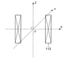
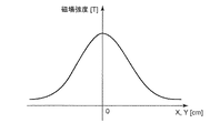
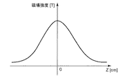
図2Aに、本発明の実施の形態における電磁石112の座標の取り方を示す。電磁石112の中心を原点とし、印加磁場方向をz軸とし、またz軸に対して垂直な軸をx,y軸とし、それぞれz軸に対して直交する。また、図2Bにx,y方向における磁場分布を示し、図2Cにz方向における磁場分布を示す。図2B及び図2Cのそれぞれにおいて、縦軸は磁場強度[T]を表し、横軸は座標[cm]を表す。これらの図より、ソレノイド型円筒磁石であるため、電磁石112の中心部である原点が、最も磁場強度が強いことがわかる。磁場勾配は、z軸第一象限が負となり、第二象限が正となる。吐出方向の乱れを抑制させるため、金属粒子130は、xy軸の磁場勾配の少ないソレノイド型円筒の電磁石112の中心部を通過することが好ましい。また、高磁場発生時には、電磁石112が発熱して磁場強度が低下する恐れがあるため、電磁石112の内部に冷却水を遠心ポンプ118で循環させている。冷却能力を最大化するため、冷却水には不凍液を使用し、−10〜0℃で管理することが好ましい。
FIG. 2A shows how to take the coordinates of the
次に、本実施形態の特徴である金属粒子130に交流磁場を印加し、磁気体積力を発現させて落下速度を減少させるメカニズムについて説明する。
Next, a mechanism for reducing the falling speed by applying an alternating magnetic field to the
金属粒子130をノズル104から回収筒113内に吐出すると、金属粒子130は表面張力により球形化したのち、金属粒子130には、重力と空気抵抗とによる力が加わる。そこに、電磁石112を用いて磁場を印加することで、上向きに磁気体積力
When the
を金属粒子130に発現し、重力の作用を低減することで、金属粒子130の落下速度(落下速度)を減少させることが可能となる。ここで、Mは磁化[A/m]、Hは電磁石112によって発生する磁場[A/m]、Vは金属粒子130である磁性体の体積[m3]、χは磁性体の磁化率[m3/kg]、ΔHは磁場勾配[A/m]、太文字はベクトル量、細文字はスカラー量を表す。
Is expressed in the
この式より、磁気体積力 From this formula, magnetic body force
の向きは、吐出した金属粒子130の磁化Mの向きと磁気勾配ΔHとによって決定されることがわかる。また、磁化Mは、磁場強度Hと金属粒子130の磁化率χとの積で表すことが出来き、金属粒子130の磁化率χの正負によって磁場の向きを上下変更することで、磁化Mの向きを制御することが出来る。
It can be seen that the direction of is determined by the direction of the magnetization M of the discharged
例として、金属粒子130が錫、銀、ビスマス、インジウム、及び、銅で形成されたSnAgBiInCuはんだの場合を示す。表1にSnAgBiInCuはんだを形成している各金属の磁化率χを表す。
As an example, the case where the
表1より、すべての形成金属の磁化率χがχ<0であり、反磁性材料であることがわかる。 From Table 1, it can be seen that the magnetic susceptibility χ of all the formed metals is χ <0 and is a diamagnetic material.
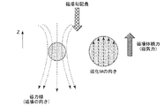
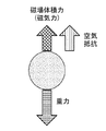
また、図3Aに、電磁石112の上部で磁場勾配が負又は下向きに磁場を印加した時にSnAgBiInCuはんだが吐出されたときに加わる力を示し、図3Bに磁気体積力を発現させたときに加わるすべての力を示す。ここで、重力方向の下向きを負とし、上向きを正とする。図3Aのように下向きに磁場を印加すると、SnAgBiInCuはんだは反磁性材料(磁化率χ<0)であるため、磁場の向きとは逆向きの上向きに磁化し、磁気体積力は上向きに加わる。そのため、図3Bのように、吐出後に加わる重力と空気抵抗とに加えて、更に磁気体積力を発現させることで、金属粒子130の落下速度を低減させることが出来る。
Also, FIG. 3A shows the force applied when SnAgBiInCu solder is ejected when a magnetic field gradient is applied negatively or downwardly at the top of the
また、金属粒子130が強磁性材料の場合は、磁化率χ>0であるため、上向きに印加する必要があり、金属粒子130の組成によって変更する必要がある。
Further, when the
以下、ノズル径300μm、500μmを用いて金属粒子径300±10μm、500±10μmを製造した実施例を示す。 Examples in which metal particle diameters of 300 ± 10 μm and 500 ± 10 μm are manufactured using nozzle diameters of 300 μm and 500 μm are shown below.
(実施例1)
前記各図に示した金属粒子製造装置において、圧電素子107として積層型圧電素子を用いた。圧電素子107の最大変位量は、14.7μmであり、周波数特性は1.7MHzである。ここでは、上述の圧電素子107の温度が40°C以上にならないように温度制御した。高温になる部材、例えばプランジャ106及びノズル104はSUS製とし、一定温度に制御を行った。また、プランジャ106の直径(約8mm)内に1個のノズル104を設けた。ノズル径は、約300μm(0.3mm)とした。
Example 1
In the metal particle manufacturing apparatus shown in each figure, a multilayer piezoelectric element was used as the
金属粒子130の組成は、鉛フリーはんだとして使用されているSn−Ag−Bi−In−Cu系合金(融点約210℃)を用い、加熱機構102を用いて250℃に加熱保持し、回収部121内には、不活性ガスである窒素ガスを圧力約1kPaで導入した。ノズル104から吐出した溶融した金属材料103は、ノズル104から約1m下方の金属粒子回収ボックス115で回収した。
The composition of the
圧電素子107の動作周波数を100Hzとして、圧電素子107の温度が一定になっていることを確認してから、金属粒子製造を8時間(約300万個)行った。また、詳細は省略するが、回収部121内にストロボカメラを設置して、吐出している金属粒子130の形状をリアルタイムで観察し、この観察結果に基づいて交流磁場制御部92で製造条件の調整を行った。
The operating frequency of the
また、回収部121における電磁石112によって、0.5〜4.5Tまで0.5T刻みで磁場を印加した場合と磁場を印加しない無磁場の場合とで、金属粒子吐出製造を行った。金属粒子回収ボックス115内に回収した金属粒子130については、無作為に1000個採取し、走査型電子顕微鏡(SEM)による粒子形状観察及び画像解析装置によるへこみ又は欠けの有無と、真球度(長辺/短辺)と、収率(300±10μmを所望粒径とする)との測定を行った。
Moreover, metal particle discharge manufacture was performed by the case where the magnetic field was applied in 0.5T increments from 0.5 to 4.5T by the
回収した金属粒子130を評価した結果を表2に示す。
Table 2 shows the results of evaluating the recovered
表2より、1.0〜2.0Tを印加した場合、金属粒子130に欠け及びへこみがなく平均真球度も1に近い値をとっており、長辺と短辺との差が約3%前後であり、実際にBGAパッケージに搭載する際も転がり抵抗なく搭載することができる。また、収率も90%以上で生産性も良いことがわかる。それ以外の範囲では、平均真球度が1.3近くで長辺と短辺との差が約30%前後あり、品質が悪いことがわかる。以降、磁場強度によって、この様に差異が生じた要因を考察する。
From Table 2, when 1.0 to 2.0 T is applied, the
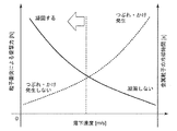
金属粒子130の落下速度と、つぶれ又は欠けと、凝固との関係を図4に示す。図4は両軸グラフとなっており、縦軸には粒子衝突による衝撃力[N]と金属粒子の冷却時間[s]とを表し、横軸には落下時間を表している。落下速度[m/s]に対し、つぶれ又は欠けと金属の凝固との関係はトレードオフの関係にあり、落下速度を速くしすぎると、金属材料103が表面張力で球形化して凝固する前に金属粒子回収ボックス115に入るため、扁平な粒子が発生する。また、金属粒子回収ボックス115に入っている粒子との粒子同士の衝突による衝撃力も大きくなってしまうので、欠け又はひびが粒子に入ってしまう。そのため、品質の良い粒子を製造するためには、ある一定の落下速度以下であることが必要である。
FIG. 4 shows the relationship between the falling speed of the
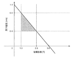
また、図5に落下速度と印加した磁場強度との関係及び実施結果を表す。縦軸は、高速度カメラ119を用いて計測(算出)した金属粒子の落下速度[m/s]を表し、横軸は、印加した磁場強度を表し、斜線部は欠け及びへこみのない金属粒子が製造可能な範囲を表している。品質の良い金属粒子を高収率で製造可能な領域は、落下速度が0.4m/s≦v≦0.8m/sの範囲(磁場強度が1.0T≦H≦2.0T)である。
FIG. 5 shows the relationship between the drop speed and the applied magnetic field strength and the results of the implementation. The vertical axis represents the falling speed [m / s] of the metal particles measured (calculated) using the high-
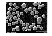
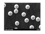
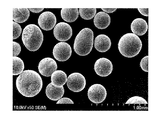
比較例1−1、実施例1−2、及び比較例1−3のときに、金属粒子回収ボックス115より回収した金属粒子130のSEM画像を、それぞれ、図6、図7、及び図8に示す。
In Comparative Example 1-1, Example 1-2, and Comparative Example 1-3, SEM images of the
図6から、無磁場の場合は、金属粒子130が円形ではなく、円形の一部が欠落した欠けが多いことがわかる。これは、落下速度が速過ぎて金属粒子回収ボックス115に回収されたときに粒子同士が衝突し変形し、又は、凝固前に落下したため変形したと考えられる。また、図8より、磁場強度が2.5Tの場合、金属粒子が磁力線方向に変形したため、円形の粒子ではなく、扁平粒子が多いことがわかる。これに対して、図7の場合、円形の粒子が多く、図6及び図8のような欠けのある粒子又は扁平粒子がほとんどないことがわかる。
From FIG. 6, it can be seen that in the case of no magnetic field, the
よって、300μmの金属粒子を欠け・かけら無く、高収率で製造するためには、磁場強度が1.0T≦H≦2.0T(落下速度が0.4m/s≦v≦0.8m/s)であることが必要である。 Therefore, in order to produce a high yield without losing or applying 300 μm of metal particles, the magnetic field strength is 1.0 T ≦ H ≦ 2.0 T (the falling speed is 0.4 m / s ≦ v ≦ 0.8 m / s).
(実施例2)
前記実施例1と同様にして、ノズル径を500μm(0.5mm)として金属粒子製造を行った。その結果を、表3に示す。所望の金属粒子径は500±10μmである。
(Example 2)
In the same manner as in Example 1, metal particles were produced with a nozzle diameter of 500 μm (0.5 mm). The results are shown in Table 3. The desired metal particle diameter is 500 ± 10 μm.
実施例1と同様に、ある印加磁場範囲である実施例2−1、2−2、2−3、2−4では、真球度が1に近く、収率も他の実施例条件とは異なって90%以上あり、欠け及びへこみのない品質の良い粒子を製造するためには、2.0T≦H≦3.5Tの磁場印加が必要であることがわかる。 Similar to Example 1, in Examples 2-1, 2-2, 2-3, 2-4, which are in a certain applied magnetic field range, the sphericity is close to 1, and the yield is also different from other example conditions. It can be seen that a magnetic field application of 2.0T ≦ H ≦ 3.5T is necessary in order to produce high-quality particles that are 90% or more and are free from chipping and dents.
実施例1では、金属粒子の最適な印加磁場強度は1.0T≦H≦2.0Tであったが、実施例2では、金属粒子の最適な印加磁場強度は2.0T≦H≦3.5Tへと増加している。これは、吐出される金属粒子の質量が増加したため、落下速度が増加したことに起因する。 In Example 1, the optimum applied magnetic field strength of the metal particles was 1.0T ≦ H ≦ 2.0T, but in Example 2, the optimum applied magnetic field strength of the metal particles was 2.0T ≦ H ≦ 3. It has increased to 5T. This is due to an increase in falling speed due to an increase in the mass of discharged metal particles.
(実施例3)
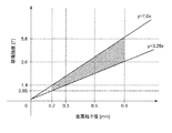
図9に実施例1及び実施例2と同様にノズル径を0.2〜0.8mmまで変更して金属粒子の吐出を行った結果を示す。縦軸に印加した磁場強度[T]を表し、横軸に吐出した金属粒子径[μm]を表し、また、斜線部はつぶれ・欠けがない金属粒子を90%以上の収率で製造できた範囲を表す。斜線部y軸の範囲は、実施例1、2の90%以上の収率で製造できた最大磁場強度2.0T、3.5Tと最小磁場強度1.0Tと2.0Tの点をそれぞれ通る最小二乗法で近似した一次関数y=7.0x、y=3.25xから決定した。よって、図9より、0.2≦粒子径x[mm]≦0.8、3.25x≦磁場強度y≦7.0xの範囲の場合、0.2〜0.8mmボールを、つぶれ・欠けなく製造可能である。
(Example 3)
FIG. 9 shows the result of discharging metal particles by changing the nozzle diameter from 0.2 to 0.8 mm in the same manner as in Example 1 and Example 2. The vertical axis represents the magnetic field strength [T] applied, the horizontal axis represents the discharged metal particle diameter [μm], and the hatched portion was able to produce metal particles with no crushing or chipping in a yield of 90% or more. Represents a range. The range of the hatched portion y-axis passes through the points of maximum magnetic field strength 2.0T, 3.5T and minimum magnetic field strength 1.0T and 2.0T, respectively, which can be manufactured with a yield of 90% or more of Examples 1 and 2. The linear function approximated by the least square method was determined from y = 7.0x and y = 3.25x. Therefore, from FIG. 9, in the case of 0.2 ≦ particle diameter x [mm] ≦ 0.8, 3.25x ≦ magnetic field strength y ≦ 7.0x, a 0.2 to 0.8 mm ball is crushed and chipped. Can be manufactured without any problem.
(製造した金属粒子の特徴)
次に、製造した金属粒子の特徴を述べる。表4に実施例1―2で作製した300μmの金属粒子に2Tの磁場を3.0cmから0.5cmずつ近づけた結果を示す。磁場を印加し、反応したものを○、反応しなかったものを×として評価した。
(Characteristics of manufactured metal particles)
Next, the characteristics of the manufactured metal particles will be described. Table 4 shows the results of bringing the 2T magnetic field closer to the 300 μm metal particles produced in Example 1-2 by 3.0 cm to 0.5 cm. When a magnetic field was applied, the reaction was evaluated as ◯, and the reaction was not evaluated as ×.
この結果より、本実施形態の製造装置を用いて製造した金属粒子は、磁場強度2Tの磁場を距離1cm以内で加えると、磁化することを特徴に持ち、別手法を用いて製造した金属粒子と判別することができる。また、評価した金属粒子は、回収部の高さが0.5m〜3.0mで製造したものである。 From this result, the metal particles manufactured using the manufacturing apparatus of the present embodiment are characterized by being magnetized when a magnetic field having a magnetic field strength of 2T is applied within a distance of 1 cm, and the metal particles manufactured using another method Can be determined. Further, the evaluated metal particles are manufactured with a height of the recovery part of 0.5 m to 3.0 m.
前記実施形態によれば、回収筒113に強磁場印加が可能な電磁石112を配置し、磁場の向き及び磁場勾配を操作することで、金属粒子130に上向きに磁気体積力(磁気力)を発現させ、落下速度を減少させることで、品質の良い(へこみ及び欠けのない)粒子を製造することが出来、収率が向上することができる。よって、落下速度が速すぎて粒子同士が衝突することがなく、へこみ及び欠けが無くて品質の良い金属粒子130を高収率で製造することができる。
According to the embodiment, the
なお、前記様々な実施形態又は変形例のうちの任意の実施形態又は変形例を適宜組み合わせることにより、それぞれの有する効果を奏するようにすることができる。また、実施形態同士の組み合わせ又は実施例同士の組み合わせ又は実施形態と実施例との組み合わせが可能であると共に、異なる実施形態又は実施例の中の特徴同士の組み合わせも可能である。 In addition, it can be made to show the effect which each has by combining arbitrary embodiment or modification of the said various embodiment or modification suitably. In addition, combinations of the embodiments, combinations of the examples, or combinations of the embodiments and examples are possible, and combinations of features in different embodiments or examples are also possible.
本発明の前記態様における金属粒子製造方法及び装置は、粒径の異なる粒子をある一定の高さで、常に安定した体積を吐出させることが可能となる。特に、磁化率が大きい溶融金属の球形成を行う場合などでは、高い直径精度で高効率製造が可能である。 The metal particle manufacturing method and apparatus according to the aspect of the present invention can always discharge a stable volume of particles having different particle diameters at a certain height. Particularly when a molten metal sphere having a high magnetic susceptibility is formed, high-efficiency production with high diameter accuracy is possible.
1 ピエゾ素子
2 供給口
3 振動棒
4 溶湯
5 溶解チャンバー
6 オリフィス
7 電極板
8 液滴
9 回収チャンバー
10 球状凝固体
11 ガス供給口
90 金属粒子製造装置
91 保持容器
92 交流磁場制御部
93 判定部
94 演算部
95 不活性ガス供給装置
96 透明窓
100 ノズルヘッド
101 供給室
102 加熱機構
103 金属材料
104 ノズル
105 圧力室
106 プランジャ
107 圧電素子
108 固定具
109 外部電源
110 ファンクションジェネレータ
111 先端部
112 電磁石
113 回収筒
114 ゲートバルブ
115 金属粒子回収ボックス
116 ファンクションジェネレータ
117 外部電源
118 遠心ポンプ
119 高速度カメラ
120 吐出部
121 回収部
130 吐出される金属材料(金属粒子)
DESCRIPTION OF
Claims (8)
圧電素子にパルス圧力を発生させ、
このパルス圧力によるプランジャの上下移動動作により、前記パルス圧力を、保持容器内に保持した前記溶融金属に伝達し、
前記パルス圧力が伝達された前記溶融金属に臨界変位以上の変位が発生して、前記保持容器に設けられたノズルから前記溶融金属を、回収筒内の不活性ガス雰囲気中に1個ずつ単分散粒子として吐出して球形化し、
前記回収筒の外部から電磁石により交流磁場を前記回収筒内に発生させ、前記回収筒内に吐出された前記単分散粒子に、上向きに磁気体積力を発現させて、前記単分散粒子の落下速度を低減させつつ前記球形化した単分散粒子を回収する、金属粒子の製造方法。 When producing metal particles from molten metal,
Generate a pulse pressure on the piezoelectric element,
By the vertical movement operation of the plunger by this pulse pressure, the pulse pressure is transmitted to the molten metal held in a holding container,
Displacement exceeding the critical displacement occurs in the molten metal to which the pulse pressure has been transmitted, and the molten metal is monodispersed one by one in an inert gas atmosphere in a collection cylinder from a nozzle provided in the holding container. Discharged as particles and spheroidized,
An alternating magnetic field is generated in the recovery cylinder by an electromagnet from the outside of the recovery cylinder, and the monodisperse particles discharged in the recovery cylinder are caused to express a magnetic volume force upward, and the falling speed of the monodisperse particles A method for producing metal particles, wherein the spheroidized monodispersed particles are recovered while reducing the amount of the particles.
請求項1に記載の金属粒子の製造方法。 The alternating magnetic field is generated in the collection cylinder by the electromagnet, and the upward magnetic volume force is expressed in the monodisperse particles discharged into the collection cylinder, thereby reducing the falling speed of the monodisperse particles. When the AC magnetic field control unit controls the AC magnetic field generated in the recovery cylinder by the electromagnet,
The manufacturing method of the metal particle of Claim 1.
前記交流磁場の磁場強度y[T]は、3.25x≦y≦7.0xである関係である、請求項1又は2に記載の金属粒子の製造方法。 The particle diameter x [mm] of the monodisperse particles is 0.2 ≦ x ≦ 0.8,
3. The method for producing metal particles according to claim 1, wherein the magnetic field strength y [T] of the alternating magnetic field has a relationship of 3.25x ≦ y ≦ 7.0x.
前記保持容器に配置されて前記溶融金属を前記保持容器から吐出するノズルと、
所定のパルス圧力を発生する圧電素子と、
前記圧電素子で発生した前記パルス圧力を前記ノズルに位置する前記溶融金属に伝達し、溶融金属側に臨界変位以上に変位させて、前記ノズルから前記溶融金属を1個ずつ単分散粒子の液滴として前記保持容器から吐出するプランジャと、
前記ノズルの下方に連通されて前記単分散粒子を凝固及び球形化する回収筒と、
前記回収筒の外部に配置されて前記回収筒内に交流磁場を発生させる電磁石と、
前記吐出されて凝固及び球形化した前記単分散粒子の落下速度が前記交流磁場により低減された状態で前記単分散粒子を回収する回収部材とを備える、
金属粒子の製造装置。 A holding container for holding molten metal;
A nozzle that is disposed in the holding container and discharges the molten metal from the holding container;
A piezoelectric element that generates a predetermined pulse pressure;
The pulse pressure generated by the piezoelectric element is transmitted to the molten metal located at the nozzle, and is displaced to the molten metal side by a critical displacement or more, so that the molten metal is dropped from the nozzle one by one with monodisperse particles. A plunger that discharges from the holding container as
A collection cylinder communicated below the nozzle to solidify and spheroidize the monodisperse particles;
An electromagnet disposed outside the recovery cylinder to generate an alternating magnetic field in the recovery cylinder;
A recovery member that recovers the monodispersed particles in a state in which the falling speed of the monodispersed particles that have been discharged, solidified, and spheroidized is reduced by the alternating magnetic field;
Metal particle manufacturing equipment.
請求項5に記載の金属粒子の製造装置。 An AC magnetic field control unit that controls the alternating magnetic field generated by the electromagnet to express the magnetic volume force upward in the metal particles and controls the falling speed of the monodisperse particles;
The apparatus for producing metal particles according to claim 5.
請求項5又は6に記載の金属粒子の製造装置。 The height of the collection part that combines the collection cylinder and the collection member is 0.5 m or more and 3.0 m or less.
The apparatus for producing metal particles according to claim 5 or 6.
請求項5〜7のいずれか1つに記載の金属粒子の製造装置。 The collection member collects metal particles that are magnetized when a magnetic field having a magnetic field strength of 2T is applied within a distance of 1 cm as the spherical monodisperse particles.
The metal particle manufacturing apparatus according to any one of claims 5 to 7.
Priority Applications (1)
| Application Number | Priority Date | Filing Date | Title |
|---|---|---|---|
| JP2016082337A JP2017190516A (en) | 2016-04-15 | 2016-04-15 | Metal particle manufacturing method and metal particle manufacturing apparatus |
Applications Claiming Priority (1)
| Application Number | Priority Date | Filing Date | Title |
|---|---|---|---|
| JP2016082337A JP2017190516A (en) | 2016-04-15 | 2016-04-15 | Metal particle manufacturing method and metal particle manufacturing apparatus |
Publications (1)
| Publication Number | Publication Date |
|---|---|
| JP2017190516A true JP2017190516A (en) | 2017-10-19 |
Family
ID=60084451
Family Applications (1)
| Application Number | Title | Priority Date | Filing Date |
|---|---|---|---|
| JP2016082337A Pending JP2017190516A (en) | 2016-04-15 | 2016-04-15 | Metal particle manufacturing method and metal particle manufacturing apparatus |
Country Status (1)
| Country | Link |
|---|---|
| JP (1) | JP2017190516A (en) |
Cited By (4)
| Publication number | Priority date | Publication date | Assignee | Title |
|---|---|---|---|---|
| CN110842209A (en) * | 2019-12-23 | 2020-02-28 | 北京工业大学 | Device for preparing uniform metal particles through pressure difference regulation and electromagnetic disturbance |
| CN114939666A (en) * | 2022-07-25 | 2022-08-26 | 浙江亚通焊材有限公司 | Particle size control method for preparing metal powder by gas atomization method |
| CN115889775A (en) * | 2022-08-22 | 2023-04-04 | 江西理工大学 | A short-process preparation device for fine-grained tungsten ingot |
| CN116638090A (en) * | 2023-04-14 | 2023-08-25 | 北京工业大学 | A device and method for preparing uniform metal particles based on electromagnetic self-excitation disturbance |
-
2016
- 2016-04-15 JP JP2016082337A patent/JP2017190516A/en active Pending
Cited By (4)
| Publication number | Priority date | Publication date | Assignee | Title |
|---|---|---|---|---|
| CN110842209A (en) * | 2019-12-23 | 2020-02-28 | 北京工业大学 | Device for preparing uniform metal particles through pressure difference regulation and electromagnetic disturbance |
| CN114939666A (en) * | 2022-07-25 | 2022-08-26 | 浙江亚通焊材有限公司 | Particle size control method for preparing metal powder by gas atomization method |
| CN115889775A (en) * | 2022-08-22 | 2023-04-04 | 江西理工大学 | A short-process preparation device for fine-grained tungsten ingot |
| CN116638090A (en) * | 2023-04-14 | 2023-08-25 | 北京工业大学 | A device and method for preparing uniform metal particles based on electromagnetic self-excitation disturbance |
Similar Documents
| Publication | Publication Date | Title |
|---|---|---|
| USRE39224E1 (en) | Apparatus and method for making uniformly sized and shaped spheres | |
| CN201208649Y (en) | Device for preparing spherical tin-based alloy powder for soldering paste by ultrasonic vibration atomization method | |
| CN108311707B (en) | Ultrafine powder preparation device and preparation method | |
| Xiong et al. | Experimental investigation on the height deviation of bumps printed by solder jet technology | |
| CN103769595A (en) | Method for preparing microcrystal and amorphous state powder material | |
| Goudar et al. | Effect of atomization parameters on size and morphology of Al-17Si alloy powder produced by free fall atomizer | |
| TWI898761B (en) | Tin metal for solder ball manufacturing | |
| Dong et al. | Size-on-demand preparation of SAC305 solder balls based on pulsated orifice ejection method | |
| JP2001226706A (en) | Apparatus for manufacturing fine metallic ball | |
| JP2001267730A (en) | Solder ball | |
| CN113560587A (en) | BGA tin ball smelting and rapid forming method | |
| JP2018090866A (en) | Molten-metal discharge device | |
| TWI603793B (en) | A hybrid atomization device | |
| CN109807339A (en) | A kind of device and method preparing hypoxemia globular metallic powder | |
| JP2001226705A (en) | Method for manufacturing fine metallic ball and apparatus for manufacturing fine metallic ball | |
| CN114850483B (en) | A device and method for quickly and efficiently screening uniform solder balls | |
| JP2001107113A (en) | Method for producing metallic glass sphere, metallic glass sphere produced by this method, and apparatus for producing the same | |
| Chao et al. | Experimental analysis of a pneumatic drop-on-demand (DOD) injection technology for 3D printing using a gallium-indium alloy | |
| CN111375775A (en) | Shock wave generator for crushing high-temperature molten metal | |
| JP2001353436A (en) | Monodisperse particle and method for manufacturing monodisperse particle and monodisperse particle manufacturing by this method for manufacture as well as apparatus for manufacturing the same | |
| JP4902119B2 (en) | Method for producing metal silicon particles | |
| KR100469018B1 (en) | method and apparatus for producing fine metal spheres of uniform sizes | |
| CN207479613U (en) | A kind of equipment for preparing hypoxemia globular metallic powder | |
| JP2006009113A (en) | Method for producing fine metal ball | |
| JP5022022B2 (en) | Monodisperse particle production equipment |