JP2017190733A - Kick starting type motorcycle - Google Patents
Kick starting type motorcycle Download PDFInfo
- Publication number
- JP2017190733A JP2017190733A JP2016081022A JP2016081022A JP2017190733A JP 2017190733 A JP2017190733 A JP 2017190733A JP 2016081022 A JP2016081022 A JP 2016081022A JP 2016081022 A JP2016081022 A JP 2016081022A JP 2017190733 A JP2017190733 A JP 2017190733A
- Authority
- JP
- Japan
- Prior art keywords
- pedal
- kick
- center stand
- lever
- vehicle
- Prior art date
- Legal status (The legal status is an assumption and is not a legal conclusion. Google has not performed a legal analysis and makes no representation as to the accuracy of the status listed.)
- Pending
Links
Images


Landscapes
- Automatic Cycles, And Cycles In General (AREA)
Abstract
【課題】センタースタンド及びキックレバーペダルの外観が損傷することを防止できるようにすること。【解決手段】車両を自立させるためのセンタースタンド(10)と、センタースタンドの近傍に設けられて内燃機関(2)を始動させるキックレバーペダル(20)とを備える。キックレバーペダルは、車両前後方向に延びるレバー部(21)と、レバー部の後端部において収納位置と踏込位置との間で回動可能に支持されるペダル部(22)とを有している。センタースタンドは、起立状態と格納状態との間で回動可能な脚部(11、12)と、脚部に設けられて運転者の足によって操作される足掛け部(17)と有している。脚部を格納状態として車両側面視したときに、足掛け部がペダル部と少なくとも交差する位置に配置され、ペダル部が踏込位置に回動されることが規制される。【選択図】図2A center stand and a kick lever pedal are prevented from being damaged in appearance. A center stand (10) for allowing a vehicle to stand by itself and a kick lever pedal (20) provided in the vicinity of the center stand for starting an internal combustion engine (2) are provided. The kick lever pedal has a lever portion (21) extending in the vehicle front-rear direction and a pedal portion (22) supported at the rear end portion of the lever portion so as to be rotatable between a storage position and a step-on position. Yes. The center stand has legs (11, 12) that can be rotated between a standing state and a retracted state, and a legrest (17) that is provided on the legs and is operated by the driver's feet. . When the leg portion is in the retracted state and viewed from the side of the vehicle, the footrest portion is disposed at a position at least crossing the pedal portion, and the pedal portion is restricted from being rotated to the depressed position. [Selection] Figure 2
Description
本発明は、キック始動式自動二輪車に関し、特に、センタースタンドを備えたキック始動式自動二輪車に関する。 The present invention relates to a kick starter motorcycle, and more particularly to a kick starter motorcycle equipped with a center stand.
従来、自動二輪車においては、セルスタータと併用してキック始動装置を備えたものが多く利用されている。キック始動装置は、先端にペダルを有するキックレバーが回動可能に設けられ、運転者がペダルを足で踏み降ろす操作を行うことでエンジンが始動される。 2. Description of the Related Art Conventionally, in motorcycles, those equipped with a kick starter in combination with a cell starter are often used. In the kick starter, a kick lever having a pedal at the tip is rotatably provided, and the engine is started when the driver performs an operation of stepping down the pedal.
ここで、特許文献1では、車両が急発進することを防止するため、駆動輪(後輪)の接地時にキックレバーの回動操作を制限している。具体的には、特許文献1の自動二輪車は、後輪を浮かせた状態で車両を自立させるセンタースタンドを備え、センタースタンドを格納状態として後輪が接地しているのにキックレバーを踏み降ろすと、キックレバーがセンタースタンドの一部に当接するようになっている。そして、この当接した状態を無視して運転者がキックレバーを更に踏み降ろすと、キックレバーに押されてセンタースタンドも回動し、センタースタンドが接地することでキックレバーの踏込みを規制している。
Here, in
しかしながら、特許文献1にあっては、運転者の踏込みの初期段階でキックレバーがセンタースタンドに当接しながら両方とも回動されるので、それらの表面が擦れたり衝突したりして外観損傷が発生する、という問題がある。
However, in
本発明はかかる点に鑑みてなされたものであり、センタースタンド及びキックレバーペダルの外観が損傷することを防止することができるキック始動式自動二輪車を提供することを目的とする。 The present invention has been made in view of this point, and an object of the present invention is to provide a kick starter type motorcycle that can prevent the appearance of the center stand and the kick lever pedal from being damaged.
本発明のキック始動式自動二輪車は、車両を自立させるためのセンタースタンドと、該センタースタンドの近傍に設けられて内燃機関を始動させるキックレバーペダルとを備えたキック始動式自動二輪車であって、前記キックレバーペダルは、車両前後方向に延びるレバー部と、該レバー部の後端部に設けられる回動軸部と、該回動軸部に支持されて収納位置と踏込位置との間で回動可能なペダル部とを有し、前記センタースタンドは、回動軸を介して起立状態と格納状態との間で回動可能な脚部と、該脚部に設けられて運転者の足によって操作される足掛け部と有し、前記脚部を格納状態として車両側面視したときに、前記足掛け部が前記ペダル部と少なくとも交差する位置に配置されることを特徴とする。 The kick start type motorcycle of the present invention is a kick start type motorcycle including a center stand for allowing the vehicle to stand on its own, and a kick lever pedal provided near the center stand for starting the internal combustion engine, The kick lever pedal includes a lever portion extending in the vehicle front-rear direction, a rotating shaft portion provided at a rear end portion of the lever portion, and supported between the rotating shaft portion and rotated between a storage position and a step-on position. The center stand has a leg portion that is rotatable between a standing state and a retracted state via a rotation shaft, and a leg portion provided on the leg portion by a driver's foot. The footrest portion is operated, and the legrest portion is disposed at a position at least crossing the pedal portion when the leg portion is in a retracted state when viewed from the side of the vehicle.
この構成によれば、センタースタンドにおける脚部の格納状態では足掛け部が邪魔になってペダル部を踏込位置に回動できなくなり、ひいては、キックレバーペダルを回動不能にすることができる。従って、キックレバーペダルを回動させることができないので、格納状態のセンタースタンドにキックレバーペダルが当接する問題も発生しなくなり、それらが擦れたり衝突したりして外観損傷が発生することを防ぐことができる。 According to this configuration, when the leg portion of the center stand is retracted, the footrest portion becomes an obstacle and the pedal portion cannot be rotated to the depressed position, and thus the kick lever pedal can be disabled. Therefore, the kick lever pedal cannot be rotated, so that the problem of the kick lever pedal coming into contact with the center stand in the retracted state does not occur, and the appearance damage caused by rubbing or colliding with them is prevented. Can do.
上記キック始動式自動二輪車において、前記キックレバーペダルは、前記ペダル部が前後方向に沿う向きに付勢する付勢部材を備えているとよい。この構成では、キックペダルの意図しない回動を規制でき、キックペダルの誤動作をより良く防止することができる。 In the kick start type motorcycle, the kick lever pedal may include a biasing member that biases the pedal portion in a direction along the front-rear direction. In this configuration, unintentional rotation of the kick pedal can be restricted, and malfunction of the kick pedal can be better prevented.
上記キック始動式自動二輪車において、前記脚部を格納状態として車両側面視したときに、前記足掛け部の上端が前記ペダル部の上面より上方に配設されるとよい。この構成では、ペダル部を操作しようとする運転者の足が足掛け部に当たり易くなってペダル部が回動不能であることを運転者により容易に認識させることができる。 In the kick start type motorcycle, the upper end of the footrest portion may be disposed above the upper surface of the pedal portion when the leg portion is in the retracted state and viewed from the side of the vehicle. In this configuration, the driver's foot who wants to operate the pedal portion can easily hit the footrest portion, and the driver can easily recognize that the pedal portion cannot rotate.
上記キック始動式自動二輪車において、前記ペダル部における収納位置と踏込位置との間の回動軌跡に重なる位置に前記足掛け部が配置されるとよい。 In the kick start type motorcycle, the footrest portion may be disposed at a position overlapping a rotation locus between the storage position and the stepping position in the pedal portion.
本発明によれば、ペダル部に対して足掛け部を上述のように配置したので、センタースタンド及びキックレバーペダルの外観が損傷することを防止することができる。 According to the present invention, since the footrest portion is disposed as described above with respect to the pedal portion, it is possible to prevent the appearance of the center stand and the kick lever pedal from being damaged.
以下、本発明の実施の形態について添付図面を参照して詳細に説明する。なお、以下においては、本発明に係るセンタースタンド及びキックレバーペダルの構造をスクータタイプの自動二輪車に適用した場合について説明するが、適用対象はこれに限定されることなく他のタイプの自動二輪車などに変更可能である。 Hereinafter, embodiments of the present invention will be described in detail with reference to the accompanying drawings. In the following, the case where the structure of the center stand and the kick lever pedal according to the present invention is applied to a scooter type motorcycle will be described, but the application target is not limited to this, and other types of motorcycles, etc. Can be changed.
図1は、本実施の形態に係るキック始動式自動二輪車の部分左側面図である。図1においては、スクータタイプの自動二輪車にユニットスイング式エンジンユニットを適用した場合について示しているが、これに限定されるものではない。また、図1においては、ユニットスイング式エンジンユニット周辺の一部の構成部品のみを示している。なお、以下の説明においては、車両前方を矢印FR、車両後方を矢印RE、車両左側を矢印L、車両右側を矢印Rでそれぞれ示すものとする。 FIG. 1 is a partial left side view of a kick starter motorcycle according to the present embodiment. Although FIG. 1 shows a case where a unit swing type engine unit is applied to a scooter type motorcycle, the present invention is not limited to this. Further, FIG. 1 shows only some components around the unit swing type engine unit. In the following description, the front of the vehicle is indicated by an arrow FR, the rear of the vehicle is indicated by an arrow RE, the left side of the vehicle is indicated by an arrow L, and the right side of the vehicle is indicated by an arrow R.
図1に示すように、ユニットスイング式エンジンユニット(以下、適宜「エンジンユニット」という)1は、車両の下方側であって、車両中央から後方側の位置に配置されている。エンジンユニット1は、図示しない車体フレームに上下方向に揺動可能に支持されている。エンジンユニット1は、内燃機関2と変速機3とが一体化して構成されている。内燃機関2は、例えば、4ストロークサイクル単気筒空冷式内燃機関で構成され、クランクケース2aと、シリンダブロック2bと、シリンダヘッド2cと、シリンダヘッドカバー2dとを含んで構成される。変速機3は、変速機ケース3a内に配置される不図示のVベルト無段変速機を備えた構成が例示できる。内燃機関2の後端部近傍では、変速機3を介して駆動力を受ける後輪4を支持している。
As shown in FIG. 1, a unit swing type engine unit (hereinafter referred to as “engine unit” as appropriate) 1 is disposed on the lower side of the vehicle and on the rear side from the center of the vehicle. The
エンジンユニット1の上方には、エアクリーナ5及びスロットルボディ6がブラケットを介して取り付けられ、エンジンユニット1と共に揺動可能に構成されている。エアクリーナ5は、走行時に取り込んだ外気を、内蔵するエアフィルタによって清浄化し、スロットルボディ6に供給する。エアクリーナ5及びスロットルボディ6の上方には、運転者が座るシート7及びラゲッジボックス8が配置されている。
Above the
エンジンユニット1の下方には、後輪4を浮かせた状態で車両を自立させるためのセンタースタンド10が回動可能に設けられている。また、変速機3の左側面側(図1の紙面で手前側)であってセンタースタンド10の近傍には、キックレバーペダル20が設けられている。キックレバーペダル20は、変速機3におけるクランク軸(不図示)にキックシャフト9等を介して連結され、回転駆動力をクランク軸に伝達して内燃機関2の始動を行えるようになる。
Below the
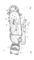
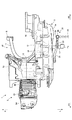
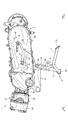
ここで、本実施の形態に係るセンタースタンド10及びキックレバーペダル20の構成について、図2〜図5を参照しながら説明する。図2は、図1を部分拡大したセンタースタンドが格納状態の左側面図であり、図3は、図2の平面図である。図4は、センタースタンドが起立状態の図2と同様の左側面図であり、図5は、図4の平面図である。
Here, the configuration of the center stand 10 and the
図2及び図3に示すように、センタースタンド10は、1本のパイプ部材を概略U字状に湾曲することで形成される右脚部11(図2では不図示)及び左脚部12を備えている。センタースタンド10には、右脚部11及び左脚部12に固定されるブラケット13が設けられている。ブラケット13は、クランクケース2aの下部に回転軸15を介して回動可能に軸支されている。従って、右脚部11及び左脚部12は、図2及び図3に示す格納状態と、図4及び図5に示す起立状態との間で回動可能となり、車両の走行状態では格納状態となる。
As shown in FIGS. 2 and 3, the
右脚部11及び左脚部12の先端側には、それぞれ湾曲形状となる板部材からなる接地部16が設けられている。図示省略したが、一方の脚部11、12には、センタースタンド10を格納状態へ付勢するばね部材が設けられている。また、左脚部12には、運転者の足によって操作されるバー状の足掛け部17が設けられている。
A
足掛け部17は、右脚部11及び左脚部12を起立状態に回動させる踏込力を右脚部11及び左脚部12へ伝える。足掛け部17は、一端部を基端部として左脚部12に溶接等によって固定され、基端部から車幅外方向(左外方向)へ向かって延びている。また、足掛け部17は、他端部となる自由端部に板状の踏付部17aが設けられている。足掛け部17は、センタースタンド10を図2に示す格納状態としたときに、自由端側が鉛直方向に向けられて上向きとなり、最上位に踏付部17aが位置するよう屈曲させて形成される。これにより、踏付部17aは、センタースタンド10の格納状態において運転者により踏込力を加えやすい位置に配置される。左脚部12と足掛け部17との間には、梁状に架け渡される補強部材18が設けられる。
The
キックレバーペダル20は、車両前後方向に延びるレバー部21と、レバー部21の後端側に支持されるペダル部22とを備えている。レバー部21は、前端側がキックシャフト9に連結され、後方へ行くに連れて緩やかに外側(左側)及び上側に湾曲しながら延出している。レバー部21の後端側には回動軸部23が設けられ、この回転軸部23を介してペダル部22が回動可能に支持されている。具体的には、図3の実線で示すようにペダル部22が前後方向に沿って配置され且つペダル部22の先端が前方に向けられる収納位置と、図3の二点鎖線で示すようにペダル部22が左右方向に沿って配置され且つペダル部22の先端が外方(左方)に向けられる踏込位置との間で回動可能となる。キックレバーペダル20において、ペダル部22を踏込位置に配置することで、ペダル部22を介して踏込力を加えることができるようになる。
The
ここで、キックレバーペダル20は、回動軸部23の軸回りに設けられたコイルばね等からなる付勢部材25を更に備えている。付勢部材25は、外部に表出せずにレバー部21やペダル部22の内部に組み込まれるように設けられる。付勢部材25は、平面視で、ペダル部22が前後方向に沿って向くような弾性力を常時発揮するようペダル部22に装着される。これにより、ペダル部22は、意図的な外力を付与しない限り図2及び図3の実線で示す収納位置に保持される。
Here, the
図2に示すセンタースタンド10の格納状態からキックレバーペダル20を用いて内燃機関2を始動させる場合、先ず、センタースタンド10を図4に示す起立状態に回動させる。この回動は、運転者が踏付部17aに足裏を載せて足掛け部17を斜め下後方に向かって踏込むことにより行われる。この踏込みによって、回転軸15を中心としてセンタースタンド10が図2中時計回りに回動され、センタースタンド10が格納状態から起立状態へ回動される。このとき、センタースタンド10では、先ず、各脚部11、12先端の接地部16を路面に接地させる。この状態で運転者が踏付部17aを更に踏み付けつつ自動二輪車を後方斜め上方に引き上げると、センタースタンド10は回転軸15を支点に揺動しつつ起立状態に向かう。そして、センタースタンド10が起立状態に配置されると、後輪4を浮かした状態で自動二輪車は自立する。自立した状態では、踏付部17aを含む足掛け部17が路面から離れている。
When the internal combustion engine 2 is started using the
センタースタンド10を起立状態としてから、図5に示すように、ペダル部22の先端が前方から左方向に向くよう運転者が足で回動操作する。そして、左右方向に向いたペダル部22を下方に向かって踏込み、キックレバーペダル20を図5の二点鎖線で示す位置まで回動することで、内燃機関2がキック始動される。
After the center stand 10 is in an upright state, as shown in FIG. 5, the driver rotates the foot with the foot so that the front end of the
続いて、センタースタンド10とキックレバーペダル20との相対位置関係について説明する。センタースタンド10(右脚部11及び左脚部12)の格納状態では、車両側面視した図2において、足掛け部17がペダル部22と少なくとも交差する位置に配置される。具体的には、図2において、先端側が上方に向けられる足掛け部17が、前後方向に延びるペダル部22と左右方向(図2中紙面直交方向)に重なっている。そして、ペダル部22の上面より足掛け部17(踏付部17a)の最上端の方が上方に位置している。この状態で、図3に示すように、ペダル部22は、変速機3の変速機ケース3aと足掛け部17との間に配置され、ペダル部22における収納位置と踏込位置との間の回動軌跡に重なるように足掛け部17が配置される。変速機ケース3aと足掛け部17との離間距離は、運転者の足が入らない距離に設定される。
Next, the relative positional relationship between the
上述のように、センタースタンド10の格納状態では、ペダル部22の左側に足掛け部17が位置するので、ペダル部22の先端が左方に向く踏込位置に回動することが足掛け部17によって規制される。従って、センタースタンド10を起立状態にしない限り、運転者がペダル部22を踏込位置に回動できずペダル部22に踏込力を加えることができなくなり、キックレバーペダル20を回動できない状態にすることができる。これにより、キックレバーペダル20の回動による足掛け部17や左脚部12とレバー部21との接触を回避でき、かかる接触に起因する足掛け部17やレバー部21等の傷付き、塗装剥がれ、変形等の外観損傷をなくすことができる。
As described above, in the retracted state of the
また、ペダル部22の上面より足掛け部17の上端が上方に配設されるので、ペダル部22を踏み込もうとすると、運転者の足裏がペダル部22に接触せずに足掛け部17に接触することとなる。この足裏の感触によってセンタースタンド10の格納状態を認識させることができ、かかる格納状態での運転者の足によるキックレバーペダル20の操作を未然に防ぐことができる。
Further, since the upper end of the
更に、付勢部材25によってペダル部22が収納位置に付勢されるので、外部に突出しない簡単な構成によってペダル部22の収納位置を維持することができ、また、ペダル部22の誤操作を防止することができる。
Further, since the
なお、本発明は上記実施の形態に限定されず、種々変更して実施することが可能である。上記実施の形態において、添付図面に図示されている大きさや形状、方向などについては、これに限定されず、本発明の効果を発揮する範囲内で適宜変更することが可能である。その他、本発明の目的の範囲を逸脱しない限りにおいて適宜変更して実施することが可能である。 In addition, this invention is not limited to the said embodiment, It can change and implement variously. In the above-described embodiment, the size, shape, direction, and the like illustrated in the accompanying drawings are not limited to this, and can be appropriately changed within a range in which the effect of the present invention is exhibited. In addition, various modifications can be made without departing from the scope of the object of the present invention.
例えば、上記実施の形態では、センタースタンド10がクランクケース2aに回動可能に支持される構成としたが、これに限られず、車両を構成するフレームにセンタースタンド10が回動可能に支持される等、種々の変更が可能である。 For example, in the above-described embodiment, the center stand 10 is rotatably supported by the crankcase 2a. However, the present invention is not limited to this, and the center stand 10 is rotatably supported by a frame constituting the vehicle. Various modifications are possible.
また、センタースタンド10の格納状態における足掛け部17の向きや位置は、車両側面視したときに足掛け部17がペダル部22と交差する限りにおいて、鉛直方向に対して傾斜する等、変更してもよい。
Further, the direction and position of the
以上説明したように、本発明は、センタースタンド及びキックレバーペダルの外観が損傷することを防止することができる、という効果を有し、センタースタンドを備えたキック始動式自動二輪車に有用である。 As described above, the present invention has an effect that the appearance of the center stand and the kick lever pedal can be prevented from being damaged, and is useful for a kick start type motorcycle including the center stand.
10 センタースタンド
11 右脚部(脚部)
12 左脚部(脚部)
15 回動軸
17 足掛け部
20 キックレバーペダル
21 レバー部
22 ペダル部
23 回動軸部
25 付勢部材
10 Center stand 11 Right leg (leg)
12 Left leg (leg)
DESCRIPTION OF SYMBOLS 15
Claims (4)
前記キックレバーペダルは、車両前後方向に延びるレバー部と、該レバー部の後端部に設けられる回動軸部と、該回動軸部に支持されて収納位置と踏込位置との間で回動可能なペダル部とを有し、
前記センタースタンドは、回動軸を介して起立状態と格納状態との間で回動可能な脚部と、該脚部に設けられて運転者の足によって操作される足掛け部と有し、
前記脚部を格納状態として車両側面視したときに、前記足掛け部が前記ペダル部と少なくとも交差する位置に配置されることを特徴とするキック始動式自動二輪車。 A kick start type motorcycle including a center stand for making a vehicle self-supporting and a kick lever pedal provided in the vicinity of the center stand for starting an internal combustion engine,
The kick lever pedal includes a lever portion extending in the vehicle front-rear direction, a rotating shaft portion provided at a rear end portion of the lever portion, and supported between the rotating shaft portion and rotated between a storage position and a step-on position. A movable pedal part,
The center stand has a leg portion that can be rotated between a standing state and a retracted state via a rotation shaft, and a legrest portion that is provided on the leg portion and is operated by a driver's foot,
The kick starter-type motorcycle, wherein the leg portion is disposed at a position at least crossing the pedal portion when the leg portion is in a retracted state when viewed from the side of the vehicle.
The kick starter type motorcycle according to any one of claims 1 to 3, wherein the footrest portion is disposed at a position overlapping a rotation locus between a storage position and a stepping position in the pedal portion. .
Priority Applications (1)
| Application Number | Priority Date | Filing Date | Title |
|---|---|---|---|
| JP2016081022A JP2017190733A (en) | 2016-04-14 | 2016-04-14 | Kick starting type motorcycle |
Applications Claiming Priority (1)
| Application Number | Priority Date | Filing Date | Title |
|---|---|---|---|
| JP2016081022A JP2017190733A (en) | 2016-04-14 | 2016-04-14 | Kick starting type motorcycle |
Publications (1)
| Publication Number | Publication Date |
|---|---|
| JP2017190733A true JP2017190733A (en) | 2017-10-19 |
Family
ID=60084711
Family Applications (1)
| Application Number | Title | Priority Date | Filing Date |
|---|---|---|---|
| JP2016081022A Pending JP2017190733A (en) | 2016-04-14 | 2016-04-14 | Kick starting type motorcycle |
Country Status (1)
| Country | Link |
|---|---|
| JP (1) | JP2017190733A (en) |
Cited By (2)
| Publication number | Priority date | Publication date | Assignee | Title |
|---|---|---|---|---|
| JP2019063184A (en) * | 2017-09-29 | 2019-04-25 | 株式会社ユニバーサルエンターテインメント | Game machine |
| JP2019063187A (en) * | 2017-09-29 | 2019-04-25 | 株式会社ユニバーサルエンターテインメント | Game machine |
-
2016
- 2016-04-14 JP JP2016081022A patent/JP2017190733A/en active Pending
Cited By (2)
| Publication number | Priority date | Publication date | Assignee | Title |
|---|---|---|---|---|
| JP2019063184A (en) * | 2017-09-29 | 2019-04-25 | 株式会社ユニバーサルエンターテインメント | Game machine |
| JP2019063187A (en) * | 2017-09-29 | 2019-04-25 | 株式会社ユニバーサルエンターテインメント | Game machine |
Similar Documents
| Publication | Publication Date | Title |
|---|---|---|
| JP5190395B2 (en) | Gear shift control device for saddle riding type vehicle | |
| US9261043B2 (en) | Stop control system for engine | |
| JP2012066714A5 (en) | ||
| JP5171554B2 (en) | Motorcycle | |
| JP4755637B2 (en) | Kick starter motorcycle | |
| JPS6081463A (en) | Kick type starting device for vehicle | |
| JP5457760B2 (en) | Protective cover structure for saddle-ride type vehicle engine case | |
| JP5555519B2 (en) | Kick pedal mechanism for saddle riding type vehicles | |
| JP6534776B2 (en) | Saddle-ride type vehicle | |
| JP2013071718A (en) | Motorcycle handle | |
| JP6761132B2 (en) | Exhaust gas sensor mounting structure | |
| JP2009073308A (en) | Motorcycle exhaust system | |
| JP3001932B2 (en) | Motorcycle brake operating device | |
| JP2751288B2 (en) | Motorcycle kick starter | |
| JP5246422B2 (en) | Motorcycle | |
| JP4359058B2 (en) | Motorcycle step structure | |
| JP2010051221A (en) | Steering device of combine harvester | |
| JPH0214991B2 (en) | ||
| JP2020055381A (en) | Fender structure for vehicle | |
| JPH0741892Y2 (en) | Kick lever device for motorcycles | |
| JP2019027369A (en) | Engine unit for saddle-ride type vehicles | |
| JP2792569B2 (en) | Soundproof structure of kick-start system for vehicles | |
| JPH02130264A (en) | Engine starting kick lever of motorcycle | |
| JP2970613B2 (en) | Scooter type vehicle with storage box | |
| JPH11263266A (en) | Step bracket device for motorcycle |