JP2017190740A - Wind power generator - Google Patents

Wind power generator Download PDF

Info

Publication number
JP2017190740A
JP2017190740A JP2016081321A JP2016081321A JP2017190740A JP 2017190740 A JP2017190740 A JP 2017190740A JP 2016081321 A JP2016081321 A JP 2016081321A JP 2016081321 A JP2016081321 A JP 2016081321A JP 2017190740 A JP2017190740 A JP 2017190740A
Authority
JP
Japan
Prior art keywords
clutch
friction plate
pinion
output shaft
hydraulic pressure
Prior art date
Legal status (The legal status is an assumption and is not a legal conclusion. Google has not performed a legal analysis and makes no representation as to the accuracy of the status listed.)
Granted
Application number
JP2016081321A
Other languages
Japanese (ja)
Other versions
JP6771935B2 (en
Inventor
主鉉 柳
Shugen Ryu
主鉉 柳
東石 良治
Ryoji Toseki
良治 東石
勝彦 横山
Katsuhiko Yokoyama
勝彦 横山
浅川 雄一
Yuichi Asakawa
雄一 浅川
Current Assignee (The listed assignees may be inaccurate. Google has not performed a legal analysis and makes no representation or warranty as to the accuracy of the list.)
Hitachi Ltd
Nabtesco Corp
Original Assignee
Hitachi Ltd
Nabtesco Corp
Priority date (The priority date is an assumption and is not a legal conclusion. Google has not performed a legal analysis and makes no representation as to the accuracy of the date listed.)
Filing date
Publication date
Application filed by Hitachi Ltd, Nabtesco Corp filed Critical Hitachi Ltd
Priority to JP2016081321A priority Critical patent/JP6771935B2/en
Priority to TW106106108A priority patent/TWI624591B/en
Priority to US15/486,534 priority patent/US20170298903A1/en
Priority to EP17166400.6A priority patent/EP3232054B1/en
Publication of JP2017190740A publication Critical patent/JP2017190740A/en
Application granted granted Critical
Publication of JP6771935B2 publication Critical patent/JP6771935B2/en
Expired - Fee Related legal-status Critical Current
Anticipated expiration legal-status Critical

Links

Images

Classifications

    • FMECHANICAL ENGINEERING; LIGHTING; HEATING; WEAPONS; BLASTING
    • F03MACHINES OR ENGINES FOR LIQUIDS; WIND, SPRING, OR WEIGHT MOTORS; PRODUCING MECHANICAL POWER OR A REACTIVE PROPULSIVE THRUST, NOT OTHERWISE PROVIDED FOR
    • F03DWIND MOTORS
    • F03D7/00Controlling wind motors 
    • F03D7/02Controlling wind motors  the wind motors having rotation axis substantially parallel to the air flow entering the rotor
    • F03D7/0204Controlling wind motors  the wind motors having rotation axis substantially parallel to the air flow entering the rotor for orientation in relation to wind direction
    • FMECHANICAL ENGINEERING; LIGHTING; HEATING; WEAPONS; BLASTING
    • F03MACHINES OR ENGINES FOR LIQUIDS; WIND, SPRING, OR WEIGHT MOTORS; PRODUCING MECHANICAL POWER OR A REACTIVE PROPULSIVE THRUST, NOT OTHERWISE PROVIDED FOR
    • F03DWIND MOTORS
    • F03D15/00Transmission of mechanical power
    • FMECHANICAL ENGINEERING; LIGHTING; HEATING; WEAPONS; BLASTING
    • F03MACHINES OR ENGINES FOR LIQUIDS; WIND, SPRING, OR WEIGHT MOTORS; PRODUCING MECHANICAL POWER OR A REACTIVE PROPULSIVE THRUST, NOT OTHERWISE PROVIDED FOR
    • F03DWIND MOTORS
    • F03D15/00Transmission of mechanical power
    • F03D15/10Transmission of mechanical power using gearing not limited to rotary motion, e.g. with oscillating or reciprocating members
    • FMECHANICAL ENGINEERING; LIGHTING; HEATING; WEAPONS; BLASTING
    • F03MACHINES OR ENGINES FOR LIQUIDS; WIND, SPRING, OR WEIGHT MOTORS; PRODUCING MECHANICAL POWER OR A REACTIVE PROPULSIVE THRUST, NOT OTHERWISE PROVIDED FOR
    • F03DWIND MOTORS
    • F03D7/00Controlling wind motors 
    • F03D7/02Controlling wind motors  the wind motors having rotation axis substantially parallel to the air flow entering the rotor
    • F03D7/022Adjusting aerodynamic properties of the blades
    • F03D7/0224Adjusting blade pitch
    • FMECHANICAL ENGINEERING; LIGHTING; HEATING; WEAPONS; BLASTING
    • F05INDEXING SCHEMES RELATING TO ENGINES OR PUMPS IN VARIOUS SUBCLASSES OF CLASSES F01-F04
    • F05BINDEXING SCHEME RELATING TO WIND, SPRING, WEIGHT, INERTIA OR LIKE MOTORS, TO MACHINES OR ENGINES FOR LIQUIDS COVERED BY SUBCLASSES F03B, F03D AND F03G
    • F05B2240/00Components
    • F05B2240/60Shafts
    • FMECHANICAL ENGINEERING; LIGHTING; HEATING; WEAPONS; BLASTING
    • F05INDEXING SCHEMES RELATING TO ENGINES OR PUMPS IN VARIOUS SUBCLASSES OF CLASSES F01-F04
    • F05BINDEXING SCHEME RELATING TO WIND, SPRING, WEIGHT, INERTIA OR LIKE MOTORS, TO MACHINES OR ENGINES FOR LIQUIDS COVERED BY SUBCLASSES F03B, F03D AND F03G
    • F05B2260/00Function
    • F05B2260/40Transmission of power
    • F05B2260/402Transmission of power through friction drives
    • F05B2260/4023Transmission of power through friction drives through a friction clutch
    • FMECHANICAL ENGINEERING; LIGHTING; HEATING; WEAPONS; BLASTING
    • F05INDEXING SCHEMES RELATING TO ENGINES OR PUMPS IN VARIOUS SUBCLASSES OF CLASSES F01-F04
    • F05BINDEXING SCHEME RELATING TO WIND, SPRING, WEIGHT, INERTIA OR LIKE MOTORS, TO MACHINES OR ENGINES FOR LIQUIDS COVERED BY SUBCLASSES F03B, F03D AND F03G
    • F05B2260/00Function
    • F05B2260/40Transmission of power
    • F05B2260/403Transmission of power through the shape of the drive components
    • F05B2260/4031Transmission of power through the shape of the drive components as in toothed gearing
    • FMECHANICAL ENGINEERING; LIGHTING; HEATING; WEAPONS; BLASTING
    • F05INDEXING SCHEMES RELATING TO ENGINES OR PUMPS IN VARIOUS SUBCLASSES OF CLASSES F01-F04
    • F05BINDEXING SCHEME RELATING TO WIND, SPRING, WEIGHT, INERTIA OR LIKE MOTORS, TO MACHINES OR ENGINES FOR LIQUIDS COVERED BY SUBCLASSES F03B, F03D AND F03G
    • F05B2260/00Function
    • F05B2260/40Transmission of power
    • F05B2260/403Transmission of power through the shape of the drive components
    • F05B2260/4031Transmission of power through the shape of the drive components as in toothed gearing
    • F05B2260/40311Transmission of power through the shape of the drive components as in toothed gearing of the epicyclic, planetary or differential type
    • FMECHANICAL ENGINEERING; LIGHTING; HEATING; WEAPONS; BLASTING
    • F05INDEXING SCHEMES RELATING TO ENGINES OR PUMPS IN VARIOUS SUBCLASSES OF CLASSES F01-F04
    • F05BINDEXING SCHEME RELATING TO WIND, SPRING, WEIGHT, INERTIA OR LIKE MOTORS, TO MACHINES OR ENGINES FOR LIQUIDS COVERED BY SUBCLASSES F03B, F03D AND F03G
    • F05B2260/00Function
    • F05B2260/70Adjusting of angle of incidence or attack of rotating blades
    • F05B2260/74Adjusting of angle of incidence or attack of rotating blades by turning around an axis perpendicular the rotor centre line
    • YGENERAL TAGGING OF NEW TECHNOLOGICAL DEVELOPMENTS; GENERAL TAGGING OF CROSS-SECTIONAL TECHNOLOGIES SPANNING OVER SEVERAL SECTIONS OF THE IPC; TECHNICAL SUBJECTS COVERED BY FORMER USPC CROSS-REFERENCE ART COLLECTIONS [XRACs] AND DIGESTS
    • Y02TECHNOLOGIES OR APPLICATIONS FOR MITIGATION OR ADAPTATION AGAINST CLIMATE CHANGE
    • Y02EREDUCTION OF GREENHOUSE GAS [GHG] EMISSIONS, RELATED TO ENERGY GENERATION, TRANSMISSION OR DISTRIBUTION
    • Y02E10/00Energy generation through renewable energy sources
    • Y02E10/70Wind energy
    • Y02E10/72Wind turbines with rotation axis in wind direction

Landscapes

  • Engineering & Computer Science (AREA)
  • Life Sciences & Earth Sciences (AREA)
  • Sustainable Development (AREA)
  • Sustainable Energy (AREA)
  • Chemical & Material Sciences (AREA)
  • Combustion & Propulsion (AREA)
  • Mechanical Engineering (AREA)
  • General Engineering & Computer Science (AREA)
  • Physics & Mathematics (AREA)
  • Fluid Mechanics (AREA)
  • Wind Motors (AREA)

Abstract

【課題】過大な力を受けた場合であっても、部品にかかる力を軽減して故障を未然に防ぐことができる風力発電装置を提供する。【解決手段】風力発電装置は、駆動装置1Aと、クラッチ油圧源94と、クラッチ制御部90とを備える。駆動装置1Aは、出力軸66からピニオン100への回転動力の伝達及び非伝達を切り換える油圧式のクラッチ機構88を有する。クラッチ油圧源94は、クラッチ機構88に油圧を供給する。クラッチ制御部90は、クラッチ油圧源94からクラッチ機構88に供給される油圧を制御する。【選択図】図5Provided is a wind turbine generator that can reduce a force applied to a component and prevent a failure even when an excessive force is applied. A wind turbine generator includes a drive device, a clutch hydraulic pressure source, and a clutch control unit. The drive device 1A includes a hydraulic clutch mechanism 88 that switches between transmission and non-transmission of rotational power from the output shaft 66 to the pinion 100. The clutch hydraulic pressure source 94 supplies hydraulic pressure to the clutch mechanism 88. The clutch control unit 90 controls the hydraulic pressure supplied from the clutch hydraulic pressure source 94 to the clutch mechanism 88. [Selection] Figure 5

Description

本発明は風力発電装置に係り、特に、リングギアを介してナセル又はブレードを回転させるための駆動装置を備える風力発電装置に関する。   The present invention relates to a wind turbine generator, and more particularly, to a wind turbine generator including a driving device for rotating a nacelle or a blade via a ring gear.

タワー上部に設置されるナセルと、当該ナセルに取り付けられる複数のブレードとを備える風車が、風力発電装置などで用いられている。ナセルはタワーに対して回転可能に設けられ、ヨー駆動装置によりタワーに対してナセルを回転駆動することで、風向きに応じてナセルを旋回させることができる。一方、ブレードは、ナセルに取り付けられたハブに対してピッチ方向に揺動可能に設置され、ピッチ駆動装置によりブレードの軸部をハブに対して回転駆動することで、ブレードのピッチ角を変えられる。   A windmill including a nacelle installed at an upper portion of a tower and a plurality of blades attached to the nacelle is used in a wind power generator or the like. The nacelle is provided so as to be rotatable with respect to the tower, and the nacelle can be turned according to the wind direction by rotating the nacelle with respect to the tower by the yaw driving device. On the other hand, the blade is installed so as to be swingable in the pitch direction with respect to the hub attached to the nacelle, and the pitch angle of the blade can be changed by rotationally driving the shaft portion of the blade with respect to the hub by a pitch driving device. .

上述の風力発電装置に用いられる駆動装置として、例えば、特許文献1に開示される偏心揺動型の減速機を好適に使用することができる。この減速機では、モータからの回転駆動力が入力ギアを介して複数のスパーギアに伝達され、クランク軸、外歯歯車及びピン内歯を含む揺動機構を介してクランク軸の公転動作及びキャリアの回転が行われる。そして、このキャリアの回転に応じて、当該キャリアにスプライン結合する出力軸が回転され、当該出力軸に取り付けられるピニオンを介して大きなトルクが得られる。   As a drive device used in the above-described wind power generator, for example, an eccentric oscillating type speed reducer disclosed in Patent Document 1 can be suitably used. In this speed reducer, the rotational driving force from the motor is transmitted to the plurality of spur gears via the input gear, and the revolution of the crankshaft and the carrier are transmitted via the swing mechanism including the crankshaft, the external gear and the pin internal teeth. Rotation takes place. Then, according to the rotation of the carrier, the output shaft that is splined to the carrier is rotated, and a large torque is obtained through a pinion attached to the output shaft.

特開2014−211204号公報JP 2014-211204 A

自然環境下に設置される風車は、予期しない風を受けて想定外の大きな外力が加えられることがある。想定外の大きな外力を風車が受けると、風車の可動部には局所的に過大な力が作用し、例えば「ブレードとハブとの連結部」や「ナセルとタワーとの連結部」において部品が破損してしまうことがある。特に、これらの連結部では、ピッチ駆動及びヨー駆動を行う駆動装置の出力軸に設けられたピニオンとリングギア等の係合体とが係合しているが、駆動装置の出力軸は、減速機に接続されていることからフリーに回転できない。そのためピニオンと係合体とが相互にロックされた状態に置かれ、風車の可動部に大きな外力が働くと駆動装置や係合体に大きな力がかかって破損しやすい。   Wind turbines installed in natural environments may receive unexpected unexpected winds and apply unexpected large external forces. When the wind turbine receives an unexpected large external force, an excessive force acts locally on the moving part of the wind turbine. For example, the parts in the `` blade and hub connection part '' and `` nacelle and tower connection part '' It may be damaged. In particular, in these connecting portions, a pinion provided on an output shaft of a driving device that performs pitch driving and yaw driving is engaged with an engaging body such as a ring gear, but the output shaft of the driving device is a reduction gear. Cannot rotate freely because it is connected to. Therefore, when the pinion and the engaging body are placed in a locked state, and a large external force is applied to the movable part of the windmill, the driving device and the engaging body are easily applied and easily damaged.

また、破損を来さない程度の外力が風車の可動部に働いている場合であっても、この状態下で駆動装置を作動させると、通常よりも大きな負荷が可動部にかかるため、やはり駆動装置や係合体は破損しやすくなる。さらに、十分なトルクを確保するため、風車の可動部には、通常、複数の駆動装置が設けられる。したがって複数の駆動装置の一つが故障によりロックされることもあるが、そのような状態で、他の風車用駆動装置が作動すると、いずれかの駆動装置のピニオンと係合体との間に大きな力がかかって破損することがある。   Even if external force that does not cause damage is acting on the moving part of the windmill, operating the drive device under this condition causes a larger load on the moving part. The device and the engagement body are easily damaged. Furthermore, in order to ensure sufficient torque, the movable part of the windmill is usually provided with a plurality of driving devices. Accordingly, one of the plurality of drive devices may be locked due to a failure. When another wind turbine drive device operates in such a state, a large force is generated between the pinion of one of the drive devices and the engagement body. May be damaged.

これらのピニオンや係合体等の部品が破損してしまうと、破損部品の交換や駆動装置自体の交換が必要になるが、そのような部品交換にはコストがかかり、部品交換が行われる間は風車の稼働を止めなければならない。特にナセルとタワーとの連結部に設けられ駆動装置と係合するリングギアは大型であり比較的高価な部品であるため、そのようなリングギアの交換作業には手間が非常にかかるだけではなく多大なコストが必要になる。   If these parts, such as pinions and engaging bodies, are damaged, replacement of damaged parts and replacement of the drive unit itself are necessary, but such parts replacement is costly and while parts are being replaced. The operation of the windmill must be stopped. In particular, the ring gear that is provided at the connecting portion between the nacelle and the tower and engages with the drive device is a large and relatively expensive part. Significant cost is required.

したがって駆動装置が想定外の過大な力を受ける場合であっても、部品にかかる力を軽減して破損等の故障を未然に防ぐことができる機構が望まれている。   Therefore, there is a demand for a mechanism that can reduce a force applied to a component and prevent a failure such as a breakage even when the driving device receives an unexpected excessive force.

本発明は上述の事情に鑑みてなされたものであり、過大な力を受けた場合であっても、部品にかかる力を軽減して故障を未然に防ぐことができる風力発電装置を提供することを目的とする。   The present invention has been made in view of the above-described circumstances, and provides a wind turbine generator that can reduce a force applied to components and prevent a failure even when an excessive force is applied. With the goal.

本発明の一態様は、リングギアと、リングギアを介してナセル又はブレードを回転させるための駆動装置と、クラッチ油圧源と、クラッチ制御部と、を備え、駆動装置は、動力軸を有するモータと、動力軸から動力が伝達され当該動力によって回転される入力ギアと、入力ギアを介して入力される動力によって回転される出力軸を有する減速部と、リングギアと噛合っており、出力軸から伝達される回転動力によって回転されるピニオンと、出力軸からピニオンへの回転動力の伝達及び非伝達を切り換える油圧式のクラッチ機構と、を有し、クラッチ油圧源は、クラッチ機構に油圧を供給し、クラッチ制御部は、クラッチ油圧源からクラッチ機構に供給される油圧を制御する風力発電装置に関する。   One aspect of the present invention includes a ring gear, a driving device for rotating a nacelle or a blade via the ring gear, a clutch hydraulic pressure source, and a clutch control unit, and the driving device includes a motor having a power shaft. And an input gear that receives power from the power shaft and is rotated by the power, a speed reduction unit that has an output shaft that is rotated by power input through the input gear, and a ring gear. And a hydraulic clutch mechanism that switches between transmission and non-transmission of rotational power from the output shaft to the pinion, and a clutch hydraulic source supplies hydraulic pressure to the clutch mechanism The clutch control unit relates to a wind turbine generator that controls the hydraulic pressure supplied from the clutch hydraulic pressure source to the clutch mechanism.

本態様によれば、過大な力を受けた場合であっても、出力軸からピニオンへの回転動力の状態をクラッチ機構によって非伝達状態に切り換えることで、ピニオンにかかる力を軽減して故障を未然に防ぐことができる。また、クラッチ油圧源およびクラッチ制御部を駆動装置と別体とすることにより駆動装置の小型化にも寄与しうる。   According to this aspect, even when an excessive force is received, the state of rotational power from the output shaft to the pinion is switched to the non-transmission state by the clutch mechanism, thereby reducing the force applied to the pinion and It can be prevented in advance. Further, by making the clutch hydraulic power source and the clutch control unit separate from the drive device, the drive device can be reduced in size.

駆動装置は、複数設けられ、クラッチ油圧源は、複数の駆動装置のそれぞれのクラッチ機構に油圧を供給してもよい。   A plurality of drive devices may be provided, and the clutch hydraulic pressure source may supply hydraulic pressure to each clutch mechanism of the plurality of drive devices.

本態様によれば、1つのクラッチ油圧源で、複数の駆動装置のクラッチ機構を駆動させることができるため、1つの駆動装置に対して1つのクラッチ油圧源を設ける構成と比べて構成を簡素化することができ、ナセルやハブ(ローター)の小型化を促進しうる。   According to this aspect, the clutch mechanism of a plurality of drive devices can be driven by one clutch hydraulic power source, so the configuration is simplified compared to a configuration in which one clutch hydraulic power source is provided for one drive device. It is possible to reduce the size of the nacelle and hub (rotor).

風力発電装置は、リングギアを介したナセル又はブレードの回転を抑止するためのギア抑止部であって、クラッチ油圧源から供給される油圧を利用してナセル又はブレードの回転を抑止するギア抑止部を更に備えてもよい。   The wind power generator is a gear suppression unit for suppressing the rotation of the nacelle or the blade via the ring gear, and the gear suppression unit for suppressing the rotation of the nacelle or the blade using the hydraulic pressure supplied from the clutch hydraulic pressure source. May be further provided.

本態様によれば、構成を簡素化することができ、ナセルやハブ(ローター)の小型化を促進しうる。   According to this aspect, the configuration can be simplified, and downsizing of the nacelle and the hub (rotor) can be promoted.

クラッチ機構は、出力軸に取り付けられる第1摩擦板と、ピニオンに取り付けられる第2摩擦板とを有し、クラッチ制御部は、第1摩擦板と第2摩擦板とを係合させることで出力軸からピニオンへの回転動力の伝達を行い、第1摩擦板と第2摩擦板との間の係合を解除することで出力軸からピニオンへの回転動力の非伝達を行ってもよい。   The clutch mechanism has a first friction plate attached to the output shaft and a second friction plate attached to the pinion, and the clutch control unit outputs the output by engaging the first friction plate and the second friction plate. Rotational power may be transmitted from the shaft to the pinion, and the engagement between the first friction plate and the second friction plate may be released so that the rotational power is not transmitted from the output shaft to the pinion.

クラッチ制御部は、第1摩擦板及び第2摩擦板のうち少なくともいずれか一方に当接されるクラッチ駆動体と、当該クラッチ駆動体の移動をコントロールすることで第1摩擦板と第2摩擦板との間の係合及び非係合を切り換えるクラッチ切換部とを有してもよい。   The clutch control unit includes a clutch driving body that is in contact with at least one of the first friction plate and the second friction plate, and controls the movement of the clutch driving body to thereby control the first friction plate and the second friction plate. And a clutch switching unit that switches between engagement and disengagement.

クラッチ駆動体は油圧ピストンを含み、クラッチ切換部は、液状伝達媒体を介して油圧ピストンの移動をコントロールして第1摩擦板と第2摩擦板との間の係合及び非係合を切り換えてもよい。   The clutch driving body includes a hydraulic piston, and the clutch switching unit controls the movement of the hydraulic piston via the liquid transmission medium to switch between engagement and disengagement between the first friction plate and the second friction plate. Also good.

駆動装置は複数設けられ、複数の駆動装置のそれぞれが有するモータで消費される電流量を検出する電流検出部が設けられ、クラッチ制御部は、電流検出部の検出結果から導き出される複数の駆動装置間におけるモータで消費される電流量の差に基づいて、複数の駆動装置のそれぞれが有するクラッチ機構にクラッチ油圧源から供給される油圧を制御してもよい。   A plurality of drive devices are provided, a current detection unit that detects a current amount consumed by a motor included in each of the plurality of drive devices is provided, and the clutch control unit is a plurality of drive devices derived from the detection result of the current detection unit The hydraulic pressure supplied from the clutch hydraulic pressure source to the clutch mechanism of each of the plurality of drive devices may be controlled based on the difference in the amount of current consumed by the motor.

本態様によれば、モータ間の消費電流量の相違に応じて、クラッチ機構をコントロールすることができる。   According to this aspect, the clutch mechanism can be controlled in accordance with the difference in current consumption between the motors.

本発明によれば、クラッチ機構によって出力軸からピニオンへの回転動力の伝達及び非伝達を切り換えることができる。したがって、駆動装置が過大な力を受けた場合であっても、出力軸からピニオンへの回転動力の状態をクラッチ機構によって非伝達状態に切り換えることで、故障を未然に防ぐことができる。   According to the present invention, transmission and non-transmission of rotational power from the output shaft to the pinion can be switched by the clutch mechanism. Therefore, even when the driving device receives an excessive force, a failure can be prevented in advance by switching the state of the rotational power from the output shaft to the pinion to the non-transmission state by the clutch mechanism.

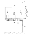
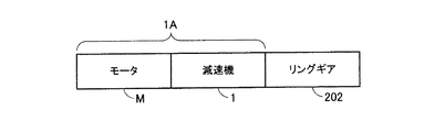
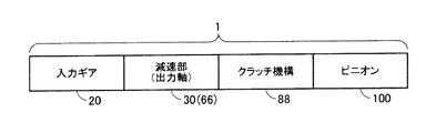
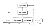
図1は、本発明の一実施形態に係る風車の一例を示す概略断面図である。FIG. 1 is a schematic cross-sectional view showing an example of a windmill according to an embodiment of the present invention. 図2は、駆動装置の構成例の概略を示す機能ブロック図である。FIG. 2 is a functional block diagram illustrating an outline of a configuration example of the driving device. 図3は、減速機の構成例の概略を示す機能ブロック図である。FIG. 3 is a functional block diagram showing an outline of a configuration example of the speed reducer. 図4は、クラッチ機構の構成例の概略を示す機能ブロック図である。FIG. 4 is a functional block diagram showing an outline of a configuration example of the clutch mechanism. 図5は、駆動装置の構成及びクラッチ機構の機能構成を例示する断面図である。FIG. 5 is a cross-sectional view illustrating the configuration of the drive device and the functional configuration of the clutch mechanism. 図6は、図5に示す構成における出力軸からピニオンへの回転動力の伝達及び非伝達のメカニズムを説明するための概念図であり、(a)は回転動力の伝達状態を示し、(b)は回転動力の非伝達状態を示す。FIG. 6 is a conceptual diagram for explaining the mechanism of transmission and non-transmission of rotational power from the output shaft to the pinion in the configuration shown in FIG. 5, (a) shows the transmission state of rotational power, (b) Indicates a non-transmission state of rotational power. 図7は、クラッチ機構及びクラッチ制御部の一変形例に係る機能構成例を示す図である。FIG. 7 is a diagram illustrating a functional configuration example according to a modification of the clutch mechanism and the clutch control unit.

以下、図面を参照して本発明の一実施形態について説明する。   Hereinafter, an embodiment of the present invention will be described with reference to the drawings.

以下の実施形態では、風車(風力発電装置)が備える駆動装置を「タワー(ベース部)に対してナセル(可動部)を回転駆動するヨー駆動装置」として使用する例について説明するが、下述の駆動装置の構成は風車の可動部をベース部に対して回転駆動させるための駆動装置全般に適用可能である。したがって、例えば「ハブ(ベース部)に対してブレード(可動部)をピッチ方向に回転駆動するピッチ駆動装置」として下述の駆動装置を使用してもよい。より具体的には、例えば後述のリングギアを介してナセル又はブレードを回転させるための駆動装置として、下述の駆動装置を使用してもよい。   In the following embodiment, an example will be described in which a driving device provided in a wind turbine (wind power generator) is used as a “yaw driving device that rotationally drives a nacelle (movable part) with respect to a tower (base part)”. The configuration of this driving device can be applied to all driving devices for rotating the movable part of the windmill relative to the base part. Therefore, for example, the following driving device may be used as a “pitch driving device that rotationally drives the blade (movable portion) in the pitch direction with respect to the hub (base portion)”. More specifically, for example, the following driving device may be used as a driving device for rotating the nacelle or the blade via a ring gear described later.

[風車(風力発電装置)]
図1は、本発明の一実施形態に係る風車200の一例を示す概略断面図である。以下の説明において「風車200」は風力発電装置を構成する装置であり、「風車200」は「風力発電装置」と同義に用いられうる。本例の風車200は、タワー201と、タワー201によって回転可能に支持されるナセル204と、ナセル204にハブ206を介して取り付けられる複数のブレード203とを備える。
[Windmill (wind power generator)]
FIG. 1 is a schematic cross-sectional view showing an example of a windmill 200 according to an embodiment of the present invention. In the following description, “windmill 200” is a device constituting a wind power generator, and “windmill 200” can be used synonymously with “wind power generator”. The windmill 200 of this example includes a tower 201, a nacelle 204 rotatably supported by the tower 201, and a plurality of blades 203 attached to the nacelle 204 via hubs 206.

タワー201は地上に設置されるベース部であり、タワー201の内側には回転駆動ギアとして形成される内歯歯車型のリングギア202が固定的に取り付けられている。ナセル204には、当該ナセル204に固定的に取り付けられる回転架台205と、当該回転架台205に取り付けられる複数(とりわけ3以上)の駆動装置1Aとが設けられている。各駆動装置1Aは、回転架台205に形成された孔から突出してリングギア202と噛み合うピニオン100を具備する。リングギア202の内側の周方向に沿ってピニオン100が複数箇所に配置されるように、各駆動装置1Aはナセル204内において位置決めされる。したがって複数の駆動装置1Aのモータが相互に同期して動力軸を回転させて、各駆動装置1Aのピニオン100を回転駆動することで、回転架台205とともにナセル204全体がタワー201に対して回転駆動(旋回駆動)される。これにより、ナセル204に取り付けられるハブ206及びブレード203の向きが変えられる。なお複数の駆動装置1Aのモータ間における動力軸の回転同期は、例えば、複数の駆動装置1Aにコントローラを接続し、当該コントローラによって各モータを制御することで行われうる。またナセル204には、ハブ206に連結される動力伝達軸、増速機、発電機及びコンバーター等が更に設けられる。   The tower 201 is a base portion installed on the ground, and an internal gear type ring gear 202 formed as a rotational drive gear is fixedly attached to the inside of the tower 201. The nacelle 204 is provided with a rotating gantry 205 fixedly attached to the nacelle 204 and a plurality (particularly three or more) of driving devices 1A attached to the rotating gantry 205. Each drive device 1 </ b> A includes a pinion 100 that protrudes from a hole formed in the rotary mount 205 and meshes with the ring gear 202. Each drive device 1 </ b> A is positioned in the nacelle 204 so that the pinions 100 are arranged at a plurality of locations along the inner circumferential direction of the ring gear 202. Accordingly, the motors of the plurality of drive devices 1A rotate the power shaft in synchronization with each other, and the pinion 100 of each drive device 1A is rotationally driven, so that the whole nacelle 204 and the rotating rack 205 are rotationally driven relative to the tower 201. (Swivel drive). Thereby, the direction of the hub 206 and the blade 203 attached to the nacelle 204 is changed. The rotation synchronization of the power shaft between the motors of the plurality of drive devices 1A can be performed, for example, by connecting a controller to the plurality of drive devices 1A and controlling each motor by the controller. The nacelle 204 is further provided with a power transmission shaft, a speed increaser, a generator, a converter, and the like connected to the hub 206.

ハブ206は、ナセル204に対して回転可能に取り付けられるとともに、複数のブレード203が軸部を介して取り付けられ、これらのブレード203は相互間の角度が均等となるように配置されている。各ブレード203は、軸部を中心にハブ206に対してピッチ方向に回転可能に設けられ、ピッチ駆動装置により回転駆動されてピッチ角が適宜変えられる。なお本例ではピッチ駆動装置の図示を省略するが、ピッチ駆動装置の構成は特に限定されず、例えば後述の駆動装置1Aと同様の構成を有するピッチ駆動装置によって各ブレード203を回転駆動することも可能である。   The hub 206 is rotatably attached to the nacelle 204, and a plurality of blades 203 are attached via shafts, and these blades 203 are arranged so that the angles between them are equal. Each blade 203 is provided so as to be able to rotate in the pitch direction with respect to the hub 206 around the shaft portion, and is rotationally driven by a pitch driving device to appropriately change the pitch angle. Although the illustration of the pitch driving device is omitted in this example, the configuration of the pitch driving device is not particularly limited. For example, each blade 203 may be rotationally driven by a pitch driving device having the same configuration as the driving device 1A described later. Is possible.

なお風車200は、図1に示す構成に限定されない。例えば、図1に示す例ではリングギア202がタワー201に対して固定的に設けられているが、リングギア202はナセル204と共に回転するように設けられてもよい。公知の風車200においても「駆動装置1A」及び当該駆動装置1Aのピニオン100と噛み合う「リングギア202」の構成態様として、様々な態様が採用されているが、以下に説明する駆動装置1Aに関連する技術は、そのような様々な構成態様の駆動装置1A及びリングギア202に対しても適用することができる。   The windmill 200 is not limited to the configuration shown in FIG. For example, in the example shown in FIG. 1, the ring gear 202 is fixedly provided with respect to the tower 201, but the ring gear 202 may be provided so as to rotate together with the nacelle 204. Also in the known windmill 200, various modes are adopted as the configuration modes of the “drive device 1A” and the “ring gear 202” that meshes with the pinion 100 of the drive device 1A, but these are related to the drive device 1A described below. The technology to be applied can be applied to the drive device 1A and the ring gear 202 having such various configurations.

[駆動装置]
まず、本実施形態に係る駆動装置1Aの構成の概略について説明する。
[Driver]
First, an outline of the configuration of the drive device 1A according to the present embodiment will be described.

図2は、駆動装置1Aの構成例の概略を示す機能ブロック図である。本例の駆動装置1Aは、モータM及び減速機1を具備し、モータMから減速機1に供給される回転動力は、減速機1により減速されてトルクが増大され、リングギア202に伝達されてヨー駆動力に変換される。   FIG. 2 is a functional block diagram showing an outline of a configuration example of the driving apparatus 1A. The drive device 1A of this example includes a motor M and a speed reducer 1. The rotational power supplied from the motor M to the speed reducer 1 is decelerated by the speed reducer 1 to increase the torque and is transmitted to the ring gear 202. Converted into yaw driving force.

図3は、減速機1の構成例の概略を示す機能ブロック図である。本例の減速機1は、モータMが有する動力軸から動力が伝達され当該動力によって回転される入力ギア20と、入力ギア20に連結される減速部30と、ピニオン100と、減速部30とピニオン100との間に介在するクラッチ機構88とを含む。減速部30は、入力ギア20を介して動力軸から入力される動力により回転される出力軸66を有する。ピニオン100は、クラッチ機構88を介して減速部30の出力軸66に連結され、出力軸66から伝達される回転動力によって回転される。クラッチ機構88は、減速部30の出力軸66からピニオン100への回転動力の伝達及び非伝達を切り換える。   FIG. 3 is a functional block diagram illustrating an outline of a configuration example of the speed reducer 1. The speed reducer 1 of this example includes an input gear 20 that receives power from a power shaft of the motor M and is rotated by the power, a speed reduction unit 30 that is coupled to the input gear 20, a pinion 100, and a speed reduction unit 30. And a clutch mechanism 88 interposed between the pinion 100 and the pinion 100. The speed reduction unit 30 has an output shaft 66 that is rotated by power input from the power shaft via the input gear 20. The pinion 100 is connected to the output shaft 66 of the speed reduction unit 30 via the clutch mechanism 88 and is rotated by the rotational power transmitted from the output shaft 66. The clutch mechanism 88 switches between transmission and non-transmission of rotational power from the output shaft 66 of the speed reduction unit 30 to the pinion 100.

図4は、クラッチ機構88の構成例の概略を示す機能ブロック図である。本例のクラッチ機構88は、減速部30の出力軸66とピニオン100との間に設けられる一対のクラッチ作動部89と、一対のクラッチ作動部89のうち少なくともいずれか一方を移動させることができるクラッチ駆動体91とを有する。各クラッチ作動部89は出力軸66及びピニオン100の各々に取り付けられており、出力軸66に取り付けられるクラッチ作動部89とピニオン100に取り付けられるクラッチ作動部89との間の係合状態(固定状態)及び非係合状態(非固定状態)がクラッチ駆動体91によって切り換えられる。クラッチ駆動体91は、出力軸66に取り付けられるクラッチ作動部89及びピニオン100に取り付けられるクラッチ作動部89のうち少なくともいずれか一方に当接され、クラッチ制御部90によって移動させられる。本例のクラッチ制御部90は、クラッチ油圧源からクラッチ機構88に供給される油圧を制御し、クラッチ駆動体91の移動をコントロールして一対のクラッチ作動部89の係合及び非係合を切り換える。またクラッチ制御部90には、複数の駆動装置1Aのそれぞれが有するモータMで消費される電流量を検出する電流検出部209が接続され、各モータMで消費される電流量に応じた検出信号が電流検出部209からクラッチ制御部90に送られる。   FIG. 4 is a functional block diagram showing an outline of a configuration example of the clutch mechanism 88. The clutch mechanism 88 of the present example can move at least one of the pair of clutch operating portions 89 provided between the output shaft 66 of the speed reduction portion 30 and the pinion 100 and the pair of clutch operating portions 89. A clutch driver 91. Each clutch operating part 89 is attached to each of the output shaft 66 and the pinion 100, and an engagement state (fixed state) between the clutch operating part 89 attached to the output shaft 66 and the clutch operating part 89 attached to the pinion 100. ) And a non-engaged state (non-fixed state) are switched by the clutch driver 91. The clutch driver 91 is brought into contact with at least one of the clutch operating part 89 attached to the output shaft 66 and the clutch operating part 89 attached to the pinion 100 and is moved by the clutch control part 90. The clutch control unit 90 of the present example controls the hydraulic pressure supplied to the clutch mechanism 88 from the clutch hydraulic pressure source, controls the movement of the clutch driver 91, and switches between engagement and disengagement of the pair of clutch operation units 89. . The clutch control unit 90 is connected to a current detection unit 209 that detects the amount of current consumed by the motor M of each of the plurality of drive devices 1A, and a detection signal corresponding to the amount of current consumed by each motor M. Is sent from the current detection unit 209 to the clutch control unit 90.

図2〜図4に示すような機能構成を有する上述の複数の駆動装置1Aにおいて想定外の事由によって特定のモータMのみで異常が発生することがあり、その特定のモータMで消費される電流量が他のモータMで消費される電流量に比べて過度に大きくなったり小さくなったりすることがある。クラッチ制御部90は、そのような特定のモータMの異常の有無を、電流検出部209から送られてくる検出信号に基づいて検知する。クラッチ制御部90は、電流検出部209の検出結果(検出信号)に基づいて特定のモータMの異常を検知した場合には、対応の一対のクラッチ作動部89間のクラッチを切る。すなわち消費電流量に関して異常を示すモータMに連結される一対のクラッチ作動部89が非係合状態にされ、出力軸66とピニオン100とが非連結状態とされる。これにより出力軸66からピニオン100に伝達される力の大きさが低減され、ピニオン100及びリングギア202等の破損などの故障を未然に防ぐことができる。   In the above-described plurality of drive devices 1A having the functional configurations shown in FIGS. 2 to 4, an abnormality may occur only in the specific motor M due to an unexpected reason, and the current consumed by the specific motor M The amount may be excessively larger or smaller than the amount of current consumed by the other motor M. The clutch control unit 90 detects the presence / absence of such abnormality of the specific motor M based on the detection signal sent from the current detection unit 209. When the clutch control unit 90 detects an abnormality of a specific motor M based on the detection result (detection signal) of the current detection unit 209, the clutch control unit 90 disconnects the clutch between the corresponding pair of clutch operation units 89. That is, the pair of clutch actuating portions 89 connected to the motor M that shows an abnormality with respect to the current consumption amount is disengaged, and the output shaft 66 and the pinion 100 are disengaged. As a result, the magnitude of the force transmitted from the output shaft 66 to the pinion 100 is reduced, and failures such as damage to the pinion 100 and the ring gear 202 can be prevented.

次に、上述の機能構成を有する駆動装置1Aの典型例について説明する。以下に示す例では、いわゆる偏心揺動型の減速部を備える駆動装置1Aに対して本発明が適用される。   Next, a typical example of the driving apparatus 1A having the above-described functional configuration will be described. In the example shown below, the present invention is applied to a drive device 1A including a so-called eccentric oscillating type deceleration unit.

図5は、駆動装置1Aの構成及びクラッチ機構の機能構成を例示する断面図である。本例の駆動装置1Aは、動力軸35を有するモータMと、動力軸35及びピニオン100の各々に連結され、動力軸35からピニオン100に動力を伝達する減速機1とを備える。この駆動装置1Aは、上述のように風車200(図1参照)のナセル204に設けられる回転架台205に対して堅固に固定される。   FIG. 5 is a cross-sectional view illustrating the configuration of the drive device 1A and the functional configuration of the clutch mechanism. The drive device 1 </ b> A of this example includes a motor M having a power shaft 35 and a speed reducer 1 that is connected to each of the power shaft 35 and the pinion 100 and transmits power from the power shaft 35 to the pinion 100. As described above, the driving device 1A is firmly fixed to the rotating frame 205 provided in the nacelle 204 of the windmill 200 (see FIG. 1).

複数の駆動装置1Aのそれぞれが有するモータMには電流検出部209が接続され、当該電流検出部209によってモータMで消費される電流量が検出される。電流検出部209にはクラッチ制御部90が接続され、電流検出部209の検出結果を示す検出信号が電流検出部209からクラッチ制御部90に送られる。本実施形態では、クラッチ制御部90が、電流検出部209からの検出信号に基づいて各モータMの異常の有無を監視及び判定する。そしてクラッチ制御部90は、電流検出部209の検出結果(検出信号)から導き出される「複数の駆動装置1A間におけるモータMで消費される電流量の差」に基づいて、複数の駆動装置1Aのそれぞれが有する一対のクラッチ作動部89(クラッチ機構88)にクラッチ油圧源から供給される油圧を制御する。   A current detection unit 209 is connected to the motor M included in each of the plurality of drive devices 1A, and the current detection unit 209 detects the amount of current consumed by the motor M. A clutch control unit 90 is connected to the current detection unit 209, and a detection signal indicating the detection result of the current detection unit 209 is sent from the current detection unit 209 to the clutch control unit 90. In the present embodiment, the clutch control unit 90 monitors and determines whether each motor M is abnormal based on the detection signal from the current detection unit 209. Then, the clutch control unit 90 is configured based on the “difference in the amount of current consumed by the motor M between the plurality of drive devices 1A” derived from the detection result (detection signal) of the current detection unit 209. The hydraulic pressure supplied from the clutch hydraulic pressure source to the pair of clutch operating portions 89 (clutch mechanism 88) included in each is controlled.

例えば何らかの事情により特定のモータMのみ動力軸35の回転がロックされて当該モータMで消費される電流量が他のモータMに比べて極端に大きくなった場合、電流検出部209からの検出信号に基づいてそのような異常状態を検知したクラッチ制御部90は、その特定のモータMとつながる出力軸66に連結されるクラッチ作動部89のクラッチを切り、出力軸66とピニオン100との連結を解除する。したがってクラッチ制御部90は、消費電流量の差が所定値以上である場合には、少なくとも消費される電流量が最も大きいモータM及び/又は最も小さいモータMを有する駆動装置1Aのクラッチ機構88(クラッチ作動部89)が出力軸66からピニオン100へ回転動力を伝達しないように、油圧を制御することができる。   For example, when the rotation of the power shaft 35 is locked only for a specific motor M for some reason and the amount of current consumed by the motor M becomes extremely large compared to other motors M, a detection signal from the current detection unit 209 is detected. The clutch control unit 90 that has detected such an abnormal state based on the clutch disengages the clutch operating unit 89 connected to the output shaft 66 connected to the specific motor M, and connects the output shaft 66 and the pinion 100. To release. Accordingly, when the difference in the amount of current consumption is equal to or greater than a predetermined value, the clutch control unit 90 has at least the motor M that consumes the largest amount of current and / or the clutch mechanism 88 ( The hydraulic pressure can be controlled so that the clutch actuating portion 89) does not transmit rotational power from the output shaft 66 to the pinion 100.

[減速機]
図5に示す減速機1は、モータMの動力軸35に連結される入力ギア20と、入力ギア20と噛み合う複数のスパーギア53と、複数のスパーギア53の各々に固定される複数のクランク軸50を有する偏心揺動型の減速部30と、クラッチ作動部89を介して減速部30の出力軸66に連結されるピニオン100と、を備える。
[Decelerator]
The reduction gear 1 shown in FIG. 5 includes an input gear 20 connected to the power shaft 35 of the motor M, a plurality of spur gears 53 that mesh with the input gear 20, and a plurality of crankshafts 50 that are fixed to the plurality of spur gears 53, respectively. And the pinion 100 connected to the output shaft 66 of the speed reduction unit 30 through the clutch operation unit 89.

減速部30は、内周側(内周面)に内歯12を有するケース10と、ケース10の内歯12と噛み合う外歯41を有する外歯歯車40と、外歯歯車40を保持するキャリア60と、クラッチ作動部89及び出力軸66を介してキャリア60に連結されるピニオン100と、を有する。ケース10は、筒状に形成され、内側に入力ギア20、複数のスパーギア53、複数のクランク軸50、外歯歯車40及びキャリア60を収容する。外歯歯車40は、外歯用軸受(図示省略)を介して複数のクランク軸50を回転自在に保持し、入力ギア20及び複数のスパーギア53の回転に応じて複数のクランク軸50により揺動される揺動ギアとして機能する。キャリア60は、各クランク軸50を回転自在に保持するとともに、複数のクランク軸50を介して外歯歯車40を保持する。   The speed reduction unit 30 includes a case 10 having internal teeth 12 on the inner peripheral side (inner peripheral surface), an external gear 40 having external teeth 41 that mesh with the internal teeth 12 of the case 10, and a carrier that holds the external gear 40. 60, and a pinion 100 connected to the carrier 60 via the clutch operating portion 89 and the output shaft 66. The case 10 is formed in a cylindrical shape, and accommodates the input gear 20, the plurality of spur gears 53, the plurality of crankshafts 50, the external gear 40, and the carrier 60 inside. The external gear 40 rotatably holds a plurality of crankshafts 50 via external tooth bearings (not shown) and swings by the plurality of crankshafts 50 according to the rotation of the input gear 20 and the plurality of spur gears 53. Functions as a rocking gear. The carrier 60 holds each crankshaft 50 rotatably, and holds the external gear 40 via the plurality of crankshafts 50.

上述の構成を有する減速機1では、モータMから入力ギア20に入力される回転動力が、減速部30により回転減速されてピニオン100から出力される。ピニオン100はリングギア202(図1参照)と噛み合うように配置されている。したがって入力ギア20及び減速部30を介してピニオン100に伝達される回転動力は、トルクが増大した状態でヨー駆動力としてリングギア202に出力される。   In the speed reducer 1 having the above-described configuration, the rotational power input from the motor M to the input gear 20 is rotationally decelerated by the speed reduction unit 30 and output from the pinion 100. The pinion 100 is disposed so as to mesh with the ring gear 202 (see FIG. 1). Therefore, the rotational power transmitted to the pinion 100 via the input gear 20 and the speed reduction unit 30 is output to the ring gear 202 as a yaw driving force in a state where the torque is increased.

図5において符号「L1」はピニオン100の中心軸を示す。ケース10の内歯12が設けられる内周面の中心軸は、中心軸L1と同軸上に位置する。以下の説明において、単に「軸方向」として表される方向は、中心軸L1上を延びる方向又は中心軸L1に平行な方向を意味する。また、中心軸L1に直交する方向を「径方向」と呼び、中心軸L1周りの方向を「周方向」と呼ぶ。   In FIG. 5, the symbol “L1” indicates the central axis of the pinion 100. The central axis of the inner peripheral surface on which the internal teeth 12 of the case 10 are provided is located coaxially with the central axis L1. In the following description, a direction represented simply as “axial direction” means a direction extending on the central axis L1 or a direction parallel to the central axis L1. A direction orthogonal to the central axis L1 is referred to as a “radial direction”, and a direction around the central axis L1 is referred to as a “circumferential direction”.

ケース10は、筒状に形成され両端部が開放されたメインケース部11aと、メインケース部11aの一端部側に固定されるサブケース部11bと、を有する。本例ではメインケース部11aの縁部とサブケース部11bの縁部とがボルト(図示省略)によって固定されることにより、メインケース部11aとサブケース部11bとは連結される。メインケース部11aのうちサブケース部11bが装着される一端部とは反対側の他端部からは、出力軸66が突出する。   The case 10 includes a main case portion 11a that is formed in a cylindrical shape and whose both end portions are open, and a sub case portion 11b that is fixed to one end portion side of the main case portion 11a. In this example, the main case part 11a and the sub case part 11b are connected by fixing the edge part of the main case part 11a and the edge part of the sub case part 11b with bolts (not shown). An output shaft 66 protrudes from the other end portion of the main case portion 11a opposite to the one end portion to which the sub case portion 11b is attached.

内歯12は、ピン状に形成された複数の内歯ピンから構成されている。これらの内歯ピンは、メインケース部11aの入力側部分111の内周面の全域にわたって周方向に沿って等間隔に複数形成されたピン溝13に嵌め込まれ、各内歯ピンの長手方向が中心軸L1と平行になるように配置されている。このような構成を有する内歯12は、上述の外歯歯車40の外歯41と噛み合うように配置されている。   The internal teeth 12 are composed of a plurality of internal teeth pins formed in a pin shape. These internal tooth pins are fitted into pin grooves 13 formed in a plurality at equal intervals along the circumferential direction over the entire inner peripheral surface of the input side portion 111 of the main case portion 11a, and the longitudinal direction of each internal tooth pin is It arrange | positions so that it may become parallel to the central axis L1. The internal teeth 12 having such a configuration are arranged so as to mesh with the external teeth 41 of the external gear 40 described above.

ケース10のサブケース部11bにはモータMが取り付けられる。モータMが有する動力軸35はサブケース部11bの内側に向かって延在し、サブケース部11b内に配置される入力ギア20と固定的に接続され、モータMによって生み出される回転動力が動力軸35を介して入力ギア20に伝達される。   A motor M is attached to the sub case portion 11 b of the case 10. The power shaft 35 of the motor M extends toward the inside of the sub case portion 11b, is fixedly connected to the input gear 20 disposed in the sub case portion 11b, and the rotational power generated by the motor M is the power shaft. 35 is transmitted to the input gear 20 via 35.

入力ギア20は平歯車構造を有し、モータMの動力軸35の中心軸及び入力ギア20の中心軸がピニオン100の中心軸L1上に位置する。入力ギア20は複数のスパーギア53の各々と噛み合うように配置され、動力軸35から入力ギア20に伝えられる回転動力が、複数のスパーギア53の各々に固定される複数のクランク軸50に伝達される。   The input gear 20 has a spur gear structure, and the central axis of the power shaft 35 of the motor M and the central axis of the input gear 20 are located on the central axis L1 of the pinion 100. The input gear 20 is arranged to mesh with each of the plurality of spur gears 53, and the rotational power transmitted from the power shaft 35 to the input gear 20 is transmitted to the plurality of crankshafts 50 fixed to each of the plurality of spur gears 53. .

減速部30を構成するキャリア60は、クランク軸50の一端部(入力ギア20及びスパーギア53側の端部)を回転自在に保持する第1保持部61と、クランク軸50の他端部(ピニオン100が突出する側の端部)を回転自在に保持する第2保持部62と、第1保持部61と第2保持部62とを連結する支柱63と、キャリア60を出力軸66と連結するための結合筒部64と、を有する。なお便宜上、図5において支柱63は二点鎖線により表される。   The carrier 60 constituting the speed reducing unit 30 includes a first holding unit 61 that rotatably holds one end of the crankshaft 50 (an end on the input gear 20 and the spur gear 53 side), and the other end (pinion) of the crankshaft 50. The second holding portion 62 that rotatably holds the end portion on the side from which 100 protrudes, the support 63 that connects the first holding portion 61 and the second holding portion 62, and the carrier 60 to the output shaft 66. A coupling cylinder part 64 for the purpose. For convenience, the column 63 is represented by a two-dot chain line in FIG.

第1保持部61及び第2保持部62はそれぞれ円環状に形成され、第1保持部61と第2保持部62とは軸方向に関して離間した位置で互いに対向して配置される。支柱63は、第1保持部61の径方向の略中央領域と第2保持部62の径方向の略中央領域との間に跨がるように設けられ、第1保持部61と第2保持部62とを連結する。結合筒部64は、第1保持部61の内周縁と第2保持部62の内周縁との間に跨がるように設けられ、円筒形状を有し、内周面においてキャリア側スプライン部65が形成されている。上述のように、このキャリア側スプライン部65が出力軸66の出力軸側スプライン部102と嵌合することで、出力軸66と減速部30とは結合される。   The first holding part 61 and the second holding part 62 are each formed in an annular shape, and the first holding part 61 and the second holding part 62 are arranged to face each other at positions separated from each other in the axial direction. The support column 63 is provided so as to straddle between a substantially central region in the radial direction of the first holding portion 61 and a substantially central region in the radial direction of the second holding portion 62, and the first holding portion 61 and the second holding portion are provided. The part 62 is connected. The coupling cylinder part 64 is provided so as to straddle between the inner peripheral edge of the first holding part 61 and the inner peripheral edge of the second holding part 62, has a cylindrical shape, and has a carrier-side spline part 65 on the inner peripheral surface. Is formed. As described above, when the carrier side spline portion 65 is fitted to the output shaft side spline portion 102 of the output shaft 66, the output shaft 66 and the speed reduction portion 30 are coupled.

第1保持部61には第1端部用貫通孔71が形成され、クランク軸50の一端部は、第1クランク軸用軸受73を介して第1端部用貫通孔71に回転自在に保持されている。また第2保持部62には第2端部用貫通孔72が形成され、クランク軸50の他端部は、第2クランク軸用軸受74を介して第2端部用貫通孔72に回転自在に保持されている。   A first end through hole 71 is formed in the first holding portion 61, and one end of the crankshaft 50 is rotatably held in the first end through hole 71 through a first crankshaft bearing 73. Has been. A second end through hole 72 is formed in the second holding portion 62, and the other end of the crankshaft 50 is rotatable to the second end through hole 72 via a second crankshaft bearing 74. Is held in.

本例のキャリア60は軸方向で二分割され、サブケース部11b側に配置される第1半体60aと、ピニオン100が突出する側に配置される第2半体60bとによって構成されている。第1半体60aは、上述の第1保持部61と、支柱63の一部を構成する第1支柱半部と、結合筒部64の一部を構成する第1筒半部64aと、を有する。一方、第2半体60bは、上述の第2保持部62と、支柱63の一部を構成する第2支柱半部と、結合筒部64の一部を構成する第2筒半部64bと、を有する。   The carrier 60 of this example is divided into two parts in the axial direction, and is constituted by a first half 60a disposed on the sub-case portion 11b side and a second half 60b disposed on the side from which the pinion 100 protrudes. . The first half 60a includes the first holding portion 61 described above, a first column half that forms part of the column 63, and a first tube half 64a that forms part of the coupling tube 64. Have. On the other hand, the second half 60 b includes the above-described second holding portion 62, a second column half that forms part of the column 63, and a second tube half 64 b that forms part of the coupling tube portion 64. Have.

第1支柱半部と第2支柱半部とにはボルト(図示省略)が跨がって挿入され、このボルトによって第1支柱半部と第2支柱半部とが連結されることで、第1半体60aと第2半体60bとが連結される。また、第1筒半部64a及び第2筒半部64bの各々の内周面には、上述のキャリア側スプライン部65が跨がって形成されている。   A bolt (not shown) is inserted across the first support column half and the second support column half, and the first support column half and the second support column half are connected by this bolt, The first half 60a and the second half 60b are connected. In addition, the carrier-side spline portion 65 is formed on the inner peripheral surface of each of the first tube half 64a and the second tube half 64b.

各クランク軸50は、シャフト本体51と、当該シャフト本体51に設けられる偏心体(図示省略)とを有し、シャフト本体51の一端部にはスパーギア53が取り付けられる。すなわちシャフト本体51の一端部は第1端部用貫通孔71からサブケース部11b側に突出し、この第1端部用貫通孔71から突出するシャフト本体51の一端部にスパーギア53が固定されている。そして、シャフト本体51のうちスパーギア53と外歯歯車40との間に配置される一端側の部分は、第1クランク軸用軸受73を介して第1端部用貫通孔71に回転自在に保持され、シャフト本体51の他端側は、第2クランク軸用軸受74を介して第2端部用貫通孔72に回転自在に保持されている。   Each crankshaft 50 has a shaft body 51 and an eccentric body (not shown) provided on the shaft body 51, and a spur gear 53 is attached to one end portion of the shaft body 51. That is, one end portion of the shaft body 51 protrudes from the first end through hole 71 toward the sub case portion 11b, and the spur gear 53 is fixed to one end portion of the shaft body 51 protruding from the first end through hole 71. Yes. A portion of one end side of the shaft main body 51 disposed between the spur gear 53 and the external gear 40 is rotatably held in the first end through hole 71 via the first crankshaft bearing 73. The other end side of the shaft body 51 is rotatably held in the second end through hole 72 via the second crankshaft bearing 74.

クランク軸50がキャリア60により保持された状態において、クランク軸50の偏心体は、キャリア60の第1保持部61と第2保持部62との間に配置される。一方、第1保持部61と第2保持部62との間に設けられる外歯歯車40には、上述のキャリア60の支柱63を通すための支柱用貫通孔(図示省略)に加え、クランク軸50を挿入するためのクランク軸用貫通孔(図示省略)が軸方向と平行に形成されている。クランク軸50の偏心体は、クランク軸用軸受(図示省略)を介して外歯歯車40のクランク軸用貫通孔内に配置される。   In a state where the crankshaft 50 is held by the carrier 60, the eccentric body of the crankshaft 50 is disposed between the first holding portion 61 and the second holding portion 62 of the carrier 60. On the other hand, the external gear 40 provided between the first holding portion 61 and the second holding portion 62 has a crankshaft in addition to a through-hole for a column (not shown) for passing the column 63 of the carrier 60 described above. A crankshaft through hole (not shown) for inserting 50 is formed in parallel with the axial direction. The eccentric body of the crankshaft 50 is disposed in the crankshaft through hole of the external gear 40 via a crankshaft bearing (not shown).

外歯歯車40の外歯41は、ケース10の内周の内歯12の歯数よりも1個或いは複数個少なくなるように設けられている。このため、クランク軸50が回転するたびに外歯41と内歯12との噛み合いがずれ、外歯歯車40が偏心運動(クランク運動)して揺動回転する。   The external teeth 41 of the external gear 40 are provided so as to be one or more than the number of teeth of the internal teeth 12 on the inner periphery of the case 10. For this reason, every time the crankshaft 50 rotates, the meshing between the external teeth 41 and the internal teeth 12 shifts, and the external gear 40 rotates eccentrically (crank motion) and swings.

このような構成を有する減速機1において、モータMの動力軸35から伝えられる回転動力により入力ギア20が回転すると、入力ギア20に噛み合う各スパーギア53が回転し、各クランク軸50が回転する。各クランク軸50が回転することで、外歯歯車40が内歯12と噛み合いをずらしながら揺動するように偏心回転する。この外歯歯車40の偏心回転に伴って、各クランク軸50は自転しながら中心軸L1を中心とした公転動作を行う。このような外歯歯車40の揺動及び偏心回転に応じたクランク軸50の公転動作により、クランク軸50を保持するキャリア60が回転する。そしてこのキャリア60の回転に応じて、キャリア60にスプライン結合された出力軸66が回転する。このようにしてモータMの動力軸35から出力軸66に回転動力が伝達され、さらにクラッチ機構88を介して出力軸66の回転動力がピニオン100に伝えられる。そして、ピニオン100からリングギア202へトルクが伝達されることで、回転架台205を具備するナセル204又はブレード203の向きが変えられる。   In the speed reducer 1 having such a configuration, when the input gear 20 is rotated by the rotational power transmitted from the power shaft 35 of the motor M, each spur gear 53 that meshes with the input gear 20 is rotated, and each crankshaft 50 is rotated. As each crankshaft 50 rotates, the external gear 40 rotates eccentrically so as to oscillate while shifting its mesh with the internal teeth 12. Along with the eccentric rotation of the external gear 40, each crankshaft 50 rotates around the central axis L1 while rotating. The carrier 60 that holds the crankshaft 50 is rotated by the revolving operation of the crankshaft 50 according to such swinging and eccentric rotation of the external gear 40. In accordance with the rotation of the carrier 60, the output shaft 66 splined to the carrier 60 rotates. In this way, rotational power is transmitted from the power shaft 35 of the motor M to the output shaft 66, and further, rotational power of the output shaft 66 is transmitted to the pinion 100 via the clutch mechanism 88. Then, by transmitting torque from the pinion 100 to the ring gear 202, the direction of the nacelle 204 or the blade 203 provided with the rotating mount 205 is changed.

[クラッチ機構]
次に、クラッチ機構88の具体的な構成例について説明する。上述のようにクラッチ機構88はクラッチ作動部89及びクラッチ駆動体91を具備し、クラッチ制御部90の制御下で作動する。クラッチ制御部90は、空圧方式及び油圧方式等の任意の動力によってクラッチ作動部89及びクラッチ駆動体91を駆動制御することが可能である。例えば図5に示す駆動装置1Aでは、油圧方式の動力によってクラッチ作動部89及びクラッチ駆動体91が駆動制御される。図5に示す例では、クラッチ油圧源94及びクラッチ制御部90等が駆動装置1Aとは別体に設置され、油等の液状伝達媒体が満たされる油圧供給路93によって、クラッチ油圧源94及びクラッチ制御部90とクラッチ駆動体91とがつながれている。クラッチ駆動体91は、液状伝達媒体により押されて軸方向に移動可能に設けられており、クラッチ駆動体91の軸方向位置に応じてクラッチ作動部89に対するクラッチ駆動体91の当接状態(押圧状態)が変わる。クラッチ制御部90は、油圧供給路93内(特にクラッチ制御部90とクラッチ駆動体91との間)の液状伝達媒体の圧力を調整することでクラッチ作動部89に対するクラッチ駆動体91の押圧力を変えることができ、クラッチ作動部89のクラッチのオンオフを制御する。
[Clutch mechanism]
Next, a specific configuration example of the clutch mechanism 88 will be described. As described above, the clutch mechanism 88 includes the clutch operating unit 89 and the clutch driver 91 and operates under the control of the clutch control unit 90. The clutch control unit 90 can drive and control the clutch operating unit 89 and the clutch driving body 91 with arbitrary power such as an air pressure method and a hydraulic method. For example, in the driving apparatus 1A shown in FIG. 5, the clutch operating unit 89 and the clutch driving body 91 are driven and controlled by hydraulic power. In the example shown in FIG. 5, the clutch hydraulic power source 94 and the clutch control unit 90 are installed separately from the drive device 1 </ b> A, and the hydraulic pressure supply path 93 is filled with a liquid transmission medium such as oil. The controller 90 and the clutch driver 91 are connected. The clutch driving body 91 is provided so as to be moved in the axial direction by being pushed by the liquid transmission medium. The clutch driving body 91 is in contact with the clutch operating portion 89 according to the axial position of the clutch driving body 91 (pressing force). State) changes. The clutch control unit 90 adjusts the pressure of the liquid transmission medium in the hydraulic pressure supply passage 93 (particularly between the clutch control unit 90 and the clutch drive body 91), thereby reducing the pressing force of the clutch drive body 91 against the clutch operation unit 89. The on / off state of the clutch actuating portion 89 is controlled.

以下に例示するクラッチ機構88及びクラッチ制御部90は、特に、リングギア202がナセル204と共に回転するように構成されるケースに適用される。すなわち本例では、リングギア202の回転を抑止するためのギア抑止部250が設けられ、当該ギア抑止部250の動力源である共有油圧源194がクラッチ油圧源94として働く。さらに、この共有油圧源194(クラッチ油圧源94)は、複数の駆動装置1Aのそれぞれのクラッチ機構88に油圧を供給する。すなわち本例に係る風車200(風力発電装置)は、共有油圧源194(クラッチ油圧源94)から供給される油圧を利用してリングギア202及びナセル204の回転を抑止するギア抑止部250を更に備え、1つの共有油圧源194がギア抑止部250及び複数の駆動装置1Aの動力源として使用される。   The clutch mechanism 88 and the clutch control unit 90 exemplified below are applied particularly to a case where the ring gear 202 is configured to rotate with the nacelle 204. That is, in this example, a gear suppression unit 250 for suppressing the rotation of the ring gear 202 is provided, and the shared hydraulic source 194 that is a power source of the gear suppression unit 250 serves as the clutch hydraulic source 94. Further, the common hydraulic pressure source 194 (clutch hydraulic pressure source 94) supplies hydraulic pressure to each clutch mechanism 88 of the plurality of drive devices 1A. That is, the wind turbine 200 (wind power generator) according to this example further includes a gear suppression unit 250 that suppresses the rotation of the ring gear 202 and the nacelle 204 using the hydraulic pressure supplied from the shared hydraulic source 194 (clutch hydraulic source 94). In addition, one shared hydraulic power source 194 is used as a power source for the gear restraint unit 250 and the plurality of drive devices 1A.

ギア抑止部250は、典型的にはキャリパーブレーキとして構成可能であり、図5に示す例では押し当て部251を含む。押し当て部251は、図示しないコントローラの制御下で移動可能であり、リングギア202に当接したりリングギア202から離間したりする。例えば、ナセル204の向きを固定する場合には、押し当て部251がリングギア202に押し当てられて、リングギア202及びナセル204が回転しないように押し当て部251によってリングギア202が保持される。一方、ナセル204の向きを可変状態にする場合には、押し当て部251がリングギア202から離間される。   The gear suppression unit 250 can typically be configured as a caliper brake, and includes a pressing unit 251 in the example shown in FIG. The pressing portion 251 can move under the control of a controller (not shown), and abuts on the ring gear 202 or moves away from the ring gear 202. For example, when the orientation of the nacelle 204 is fixed, the pressing portion 251 is pressed against the ring gear 202, and the ring gear 202 is held by the pressing portion 251 so that the ring gear 202 and the nacelle 204 do not rotate. . On the other hand, when the direction of the nacelle 204 is changed to a variable state, the pressing portion 251 is separated from the ring gear 202.

ギア抑止部250には、油圧モータ252により駆動される共有油圧源194が接続され、共有油圧源194からギア抑止部250に供給される油圧(すなわち液状伝達媒体を介して伝達される圧力)が利用されて押し当て部251の推進力(すなわち押し当て部251による保持力)が得られている。共有油圧源194には、油圧供給路93を介してリリーフ弁98、アキュムレータ95及びドレン弁99が順次接続されており、これらの要素はギア抑止部250の駆動制御に用いられる。また共有油圧源194とリリーフ弁98とを連結する油圧供給路93は途中で分岐しており、この分岐した油圧供給路93は圧力調整弁(電磁弁)90aに接続され、この分岐した油圧供給路93を介して共有油圧源194と圧力調整弁90aとが連結されている。   A shared hydraulic pressure source 194 driven by a hydraulic motor 252 is connected to the gear suppression unit 250, and the hydraulic pressure (that is, the pressure transmitted through the liquid transmission medium) supplied from the shared hydraulic source 194 to the gear suppression unit 250. The propulsive force of the pressing portion 251 (that is, the holding force by the pressing portion 251) is obtained by being used. A relief valve 98, an accumulator 95, and a drain valve 99 are sequentially connected to the common hydraulic power source 194 via a hydraulic pressure supply passage 93, and these elements are used for driving control of the gear restraining unit 250. Further, a hydraulic pressure supply path 93 that connects the shared hydraulic pressure source 194 and the relief valve 98 is branched in the middle, and the branched hydraulic pressure supply path 93 is connected to a pressure regulating valve (electromagnetic valve) 90a. The common hydraulic pressure source 194 and the pressure regulating valve 90a are connected via a path 93.

一方、クラッチ機構88のクラッチ作動部89を介し、出力軸66からピニオン100への回転動力の伝達及び非伝達が切り換えられる。クラッチ作動部89は、出力軸66に対してスプライン結合により連結される第1摩擦板89aと、ピニオン100に対してスプライン結合により連結される第2摩擦板89bとを有する(後述の図6(a)及び図6(b)参照)。第1摩擦板89a及び第2摩擦板89bは、中心軸L1周りの回転方向の挙動に関しては出力軸66及びピニオン100にそれぞれ拘束されるが、中心軸L1方向に関しては出力軸66及びピニオン100には拘束されずに移動可能に設けられている。ただし、第1摩擦板89a及び第2摩擦板89bの中心軸L1方向の挙動は、第1摩擦板89a及び第2摩擦板89bの下方に設けられるクラッチ駆動体91及び第1連結部材107によって拘束され、第1摩擦板89a及び第2摩擦板89bの脱落が防がれている。   On the other hand, transmission and non-transmission of rotational power from the output shaft 66 to the pinion 100 are switched via the clutch operating portion 89 of the clutch mechanism 88. The clutch operating unit 89 includes a first friction plate 89a connected to the output shaft 66 by spline coupling, and a second friction plate 89b connected to the pinion 100 by spline coupling (FIG. 6 described later). a) and FIG. 6B). The first friction plate 89a and the second friction plate 89b are constrained by the output shaft 66 and the pinion 100 with respect to the behavior in the rotation direction around the central axis L1, respectively, but the output shaft 66 and the pinion 100 are in the direction of the central axis L1. Is provided to be movable without being restricted. However, the behavior of the first friction plate 89a and the second friction plate 89b in the direction of the central axis L1 is restricted by the clutch driver 91 and the first connecting member 107 provided below the first friction plate 89a and the second friction plate 89b. Thus, the first friction plate 89a and the second friction plate 89b are prevented from falling off.

第1連結部材107は、出力軸66の先端部にネジ部材107aを介して取り付けられ、クラッチ駆動体91の内側に配置される。第1連結部材107の外周部は、中心軸L1に対し垂直な方向に関して出力軸66よりも僅かに突出して第1摩擦板89a及び第2摩擦板89bの下方に配置される。この第1連結部材107の外周部は、第1連結部材107によって支持される第1摩擦板89a及び第2摩擦板89bが相互間で押圧し合わずに第1摩擦板89aと第2摩擦板89bとの間で摩擦力が生じないような位置に、配置される。   The first connecting member 107 is attached to the distal end portion of the output shaft 66 via a screw member 107 a and is disposed inside the clutch driver 91. The outer peripheral portion of the first connecting member 107 is disposed below the first friction plate 89a and the second friction plate 89b so as to slightly protrude from the output shaft 66 in the direction perpendicular to the central axis L1. The outer peripheral portion of the first connecting member 107 has the first friction plate 89a and the second friction plate without the first friction plate 89a and the second friction plate 89b supported by the first connecting member 107 pressing each other. It is arranged at a position where no frictional force is generated with respect to 89b.

クラッチ駆動体91は、ピニオン100の内側でクラッチ作動部89(第1摩擦板89a及び第2摩擦板89b)よりも下方において、中心軸L1方向へ移動可能に設けられている。クラッチ駆動体91の下部の一部は切り欠かれており、このクラッチ駆動体91の切欠部には弾性部材92が挿入されている。図5に示す弾性部材92は、板バネによって構成され、ピニオン100の下部にネジ部材109aを介して取り付けられる第3連結部材109と、クラッチ駆動体91とによって保持されている。弾性部材92は、自らの弾性力を利用して、クラッチ作動部89(第1摩擦板89a及び第2摩擦板89b)にクラッチ駆動体91が押し当てられるように、中心軸L1方向に関してクラッチ駆動体91に押圧力を加える。   The clutch driver 91 is provided inside the pinion 100 so as to be movable in the direction of the central axis L1 below the clutch actuating portion 89 (the first friction plate 89a and the second friction plate 89b). A part of the lower portion of the clutch driving body 91 is cut out, and an elastic member 92 is inserted into the cutout portion of the clutch driving body 91. The elastic member 92 shown in FIG. 5 is configured by a leaf spring, and is held by a third connecting member 109 attached to the lower part of the pinion 100 via a screw member 109a and a clutch driver 91. The elastic member 92 uses its own elastic force to drive the clutch with respect to the direction of the central axis L1 so that the clutch driving body 91 is pressed against the clutch operating portion 89 (the first friction plate 89a and the second friction plate 89b). A pressing force is applied to the body 91.

ピニオン100の下部の一部は切り欠かれており、このピニオン100の切欠部にはクラッチ駆動体91の一部が挿入されている。このピニオン100の切欠部は、中心軸L1方向に関し、当該切欠部に挿入されるクラッチ駆動体91の一部よりも大きく形成されており、クラッチ駆動体91はピニオン100の切欠部が許容する範囲で中心軸L1方向へ移動可能に設けられている。すなわちクラッチ駆動体91は、「ピニオン100に接する位置(上端位置)」と「第3連結部材109に接する位置(下端位置)」との間で、ピニオン100及び第1連結部材107に沿ってスライド移動することができる。クラッチ駆動体91が上端位置以外の位置に配置される場合、ピニオン100とクラッチ駆動体91との間にはスペースが形成され、当該スペースが、油圧供給路93からの液状伝達媒体が流出入する油圧作用部93bを構成する。なおクラッチ駆動体91が上端位置に配置される場合には、ピニオン100とクラッチ駆動体91との間にスペース(油圧作用部93b)が形成されてもよいし、形成されなくてもよい。   A part of the lower part of the pinion 100 is notched, and a part of the clutch driving body 91 is inserted into the notch part of the pinion 100. The notch portion of the pinion 100 is formed larger than a part of the clutch drive body 91 inserted into the notch portion with respect to the direction of the central axis L1, and the clutch drive body 91 is within a range allowed by the notch portion of the pinion 100. Are provided so as to be movable in the direction of the central axis L1. That is, the clutch driver 91 slides along the pinion 100 and the first connecting member 107 between the “position in contact with the pinion 100 (upper position)” and the “position in contact with the third connecting member 109 (lower end position)”. Can move. When the clutch driving body 91 is disposed at a position other than the upper end position, a space is formed between the pinion 100 and the clutch driving body 91, and the liquid transmission medium from the hydraulic pressure supply passage 93 flows into and out of the space. The hydraulic action part 93b is configured. When the clutch driving body 91 is disposed at the upper end position, a space (hydraulic action portion 93b) may be formed between the pinion 100 and the clutch driving body 91, or may not be formed.

油圧作用部93bは、ピニオン100とクラッチ駆動体91との間に設けられるOリング等のシーリング部材によって液密構造を有するが、ピニオン100内に形成される油圧供給路93と連通する。ピニオン100内に形成される油圧供給路93は、第3連結部材109内に形成される油圧供給路93と連通し、第3連結部材109内に形成される油圧供給路93は圧力調整弁90aから延在する油圧供給路93とスイベルジョイントを介して連通する。したがって、共有油圧源194と油圧作用部93bとは油圧供給路93を介して連通される。なお、圧力調整弁90aと第3連結部材109との間の油圧供給路93にはドレン弁199が設けられている。   The hydraulic operating portion 93 b has a liquid-tight structure by a sealing member such as an O-ring provided between the pinion 100 and the clutch driving body 91, but communicates with a hydraulic pressure supply passage 93 formed in the pinion 100. The hydraulic pressure supply path 93 formed in the pinion 100 communicates with the hydraulic pressure supply path 93 formed in the third connection member 109, and the hydraulic pressure supply path 93 formed in the third connection member 109 is a pressure regulating valve 90a. Communicating with a hydraulic supply passage 93 extending from the through a swivel joint. Therefore, the shared hydraulic pressure source 194 and the hydraulic pressure action part 93 b are communicated with each other via the hydraulic pressure supply path 93. A drain valve 199 is provided in the hydraulic pressure supply passage 93 between the pressure regulating valve 90a and the third connecting member 109.

圧力調整弁90aには、電流検出部209からの検出信号が入力される通電コントローラ90bが接続されている。通電コントローラ90bは、電流検出部209からの検出信号に基づいて、圧力調整弁90aの消磁及び励磁の状態をコントロールする。例えば、電流検出部209からの検出信号が「複数の駆動装置1A間におけるモータMで消費される電流量の差が所定値よりも小さい」ことを示す場合、通電コントローラ90bは、圧力調整弁90aを通電せずに消磁状態として閉弁状態とする。一方、電流検出部209からの検出信号が「複数の駆動装置1A間におけるモータMで消費される電流量の差が所定値以上」を示す場合、通電コントローラ90bは、少なくとも消費電流量が最も大きい及び/又は最も小さいモータMを有する駆動装置1Aに供給される油圧を制御する圧力調整弁90aに電圧を印加して通電することでその圧力調整弁90aを励磁状態として開弁状態とする。圧力調整弁90aが開弁されると、共有油圧源194からの液状伝達媒体がピニオン100内の油圧供給路93に流れ込み、比較的高い圧力を持った液状伝達媒体が油圧作用部93bに流入する。油圧供給路93から油圧作用部93bに流入した高圧の液状伝達媒体によって、クラッチ駆動体91は押し下げられてクラッチ作動部89(第1摩擦板89a及び第2摩擦板89b)から離間する方向に移動する。   An energization controller 90b to which a detection signal from the current detection unit 209 is input is connected to the pressure adjustment valve 90a. The energization controller 90b controls the demagnetization and excitation states of the pressure adjustment valve 90a based on the detection signal from the current detection unit 209. For example, when the detection signal from the current detection unit 209 indicates that “the difference in the amount of current consumed by the motor M between the plurality of drive devices 1A is smaller than a predetermined value”, the energization controller 90b includes the pressure adjustment valve 90a. The valve is closed as a demagnetized state without energizing. On the other hand, when the detection signal from the current detection unit 209 indicates that “the difference in the amount of current consumed by the motor M among the plurality of drive devices 1A is equal to or greater than a predetermined value”, the energization controller 90b has at least the largest amount of current consumption. And / or by applying a voltage to the pressure regulating valve 90a that controls the hydraulic pressure supplied to the driving device 1A having the smallest motor M and energizing the pressure regulating valve 90a, the pressure regulating valve 90a is brought into an excited state to be opened. When the pressure regulating valve 90a is opened, the liquid transmission medium from the shared hydraulic power source 194 flows into the hydraulic pressure supply passage 93 in the pinion 100, and the liquid transmission medium having a relatively high pressure flows into the hydraulic operation section 93b. . The clutch driving body 91 is pushed down by the high-pressure liquid transmission medium flowing from the hydraulic supply passage 93 into the hydraulic operation section 93b and moves away from the clutch operation section 89 (the first friction plate 89a and the second friction plate 89b). To do.

図6は、図5に示す例における出力軸66からピニオン100への回転動力の伝達及び非伝達のメカニズムを説明するための概念図であり、(a)は回転動力の伝達状態を示し、(b)は回転動力の非伝達状態を示す。なお図6(a)及び(b)では、作動メカニズムの理解を容易にするため、各要素の表示が簡略化されており、一部要素の図示が省略されている。   FIG. 6 is a conceptual diagram for explaining the mechanism of transmission and non-transmission of rotational power from the output shaft 66 to the pinion 100 in the example shown in FIG. b) shows the non-transmission state of rotational power. In FIGS. 6A and 6B, in order to facilitate understanding of the operation mechanism, the display of each element is simplified, and the illustration of some elements is omitted.

出力軸66からピニオン100に回転動力を伝達する際には、図5に示す圧力調整弁90aは閉じられて油圧供給路93内の液状伝達媒体の流通を遮断し、圧力調整弁90aからピニオン100内に至る油圧供給路93内の圧力が低く保たれる。この場合、図6(a)に示すように、クラッチ駆動体91が弾性部材92によって押し上げられ、第1摩擦板89a及び第2摩擦板89bは、クラッチ駆動体91とピニオン100との間に挟まれて中心軸L1方向に関して相互に押圧される。これにより第1摩擦板89a及び第2摩擦板89bは相互に摩擦係合して出力軸66からの回転動力をピニオン100に伝え、ピニオン100は第1摩擦板89a及び第2摩擦板89bを介して出力軸66と一体的に回転する。   When transmitting rotational power from the output shaft 66 to the pinion 100, the pressure regulating valve 90a shown in FIG. 5 is closed to block the flow of the liquid transmission medium in the hydraulic pressure supply passage 93, and the pressure regulating valve 90a to the pinion 100. The pressure in the hydraulic pressure supply passage 93 leading to the inside is kept low. In this case, as shown in FIG. 6A, the clutch driving body 91 is pushed up by the elastic member 92, and the first friction plate 89a and the second friction plate 89b are sandwiched between the clutch driving body 91 and the pinion 100. Thus, they are pressed against each other in the direction of the central axis L1. As a result, the first friction plate 89a and the second friction plate 89b frictionally engage with each other to transmit the rotational power from the output shaft 66 to the pinion 100, and the pinion 100 passes through the first friction plate 89a and the second friction plate 89b. And rotate integrally with the output shaft 66.

なお、この場合、必要に応じて図5に示すドレン弁199が開かれて圧力調整弁90aからピニオン100内に至る油圧供給路93内の液状伝達媒体が排出されることで、油圧供給路93内の圧力が積極的に下げられてもよい。したがって、後述のように圧力調整弁90aから油圧作用部93bに至る油圧供給路93内が高圧の液状伝達媒体で満たされて出力軸66とピニオン100との間で回転動力が非伝達とされても、ドレン弁199を開くことで、駆動装置1Aを再び使用できる。すなわちドレン弁199を開いて液状伝達媒体を排出して油圧供給路93内の圧力を下げることで、クラッチ駆動体91は弾性部材92によって押し上げられ、第1摩擦板89a及び第2摩擦板89bは再び摩擦係合し、出力軸66からピニオン100に回転動力を伝達することができる。   In this case, if necessary, the drain valve 199 shown in FIG. 5 is opened and the liquid transmission medium in the hydraulic supply passage 93 extending from the pressure regulating valve 90a into the pinion 100 is discharged, so that the hydraulic supply passage 93 is discharged. The internal pressure may be actively reduced. Therefore, as will be described later, the inside of the hydraulic pressure supply passage 93 extending from the pressure regulating valve 90a to the hydraulic pressure action portion 93b is filled with a high-pressure liquid transmission medium, and rotational power is not transmitted between the output shaft 66 and the pinion 100. However, by opening the drain valve 199, the drive device 1A can be used again. That is, by opening the drain valve 199 and discharging the liquid transmission medium to lower the pressure in the hydraulic pressure supply passage 93, the clutch driver 91 is pushed up by the elastic member 92, and the first friction plate 89a and the second friction plate 89b are The friction engagement is again performed, and the rotational power can be transmitted from the output shaft 66 to the pinion 100.

一方、出力軸66からピニオン100に回転動力を非伝達とする際には、圧力調整弁90aは開かれて油圧供給路93内の液状伝達媒体の流通を許容し、高圧の液状伝達媒体が共有油圧源194からピニオン100内の油圧供給路93に送られる。そして、ピニオン100内の油圧供給路93から油圧作用部93bに高圧の液状伝達媒体が流入し、弾性部材92の弾性力に抗して、第1摩擦板89a及び第2摩擦板89bから離間する方向へクラッチ駆動体91が移動する。これにより第1摩擦板89a及び第2摩擦板89bの相互間の押圧力が低減し、第1摩擦板89aと第2摩擦板89bとの間の摩擦係合は解除され、出力軸66の回転動力がピニオン100に伝達されなくなる。そのため、出力軸66及び第1摩擦板89aが中心軸L1周りに回転しても、第2摩擦板89b及びピニオン100は基本的に回転しない。   On the other hand, when the rotational power is not transmitted from the output shaft 66 to the pinion 100, the pressure regulating valve 90a is opened to allow the liquid transmission medium in the hydraulic supply passage 93 to flow, and the high-pressure liquid transmission medium is shared. It is sent from the hydraulic pressure source 194 to the hydraulic pressure supply path 93 in the pinion 100. Then, a high-pressure liquid transmission medium flows from the hydraulic pressure supply passage 93 in the pinion 100 to the hydraulic action portion 93b, and is separated from the first friction plate 89a and the second friction plate 89b against the elastic force of the elastic member 92. The clutch driver 91 moves in the direction. Accordingly, the pressing force between the first friction plate 89a and the second friction plate 89b is reduced, the frictional engagement between the first friction plate 89a and the second friction plate 89b is released, and the rotation of the output shaft 66 is performed. The power is not transmitted to the pinion 100. Therefore, even if the output shaft 66 and the first friction plate 89a rotate around the central axis L1, the second friction plate 89b and the pinion 100 do not basically rotate.

したがって、「複数の駆動装置1A間におけるモータMで消費される電流量の差が所定値よりも小さい」間は、圧力調整弁90aは通電コントローラ90bの制御下で閉弁状態にされ、弾性部材92によりクラッチ駆動体91が第2摩擦板89bに押し当てられて、第1摩擦板89aと第2摩擦板89bとは係合する。これにより、出力軸66とピニオン100とは第1摩擦板89a及び第2摩擦板89bを介して連結され、出力軸66の回転動力が、第1摩擦板89a及び第2摩擦板89bを介してピニオン100に伝達される。   Therefore, while the “difference in the amount of current consumed by the motor M among the plurality of drive devices 1A is smaller than a predetermined value”, the pressure adjustment valve 90a is closed under the control of the energization controller 90b, and the elastic member The clutch driving body 91 is pressed against the second friction plate 89b by 92, and the first friction plate 89a and the second friction plate 89b are engaged. As a result, the output shaft 66 and the pinion 100 are coupled via the first friction plate 89a and the second friction plate 89b, and the rotational power of the output shaft 66 is transmitted via the first friction plate 89a and the second friction plate 89b. It is transmitted to the pinion 100.

一方、特定の駆動装置1A(特にモータMの動力軸35の回転動作)に関して何らかの異常が生じて「複数の駆動装置1A間におけるモータMで消費される電流量の差が所定値以上」の場合には、圧力調整弁90aは通電コントローラ90bの制御下で通電されて開弁状態にされ、高圧の液状伝達媒体が油圧供給路93から油圧作用部93bに流入する。これにより、クラッチ駆動体91が押し下げられて、第1摩擦板89aと第2摩擦板89bとの間の係合が解除され、出力軸66とピニオン100とは非連結状態となり、ピニオン100やピニオン100に係合するリングギア202の破損を未然に防ぐことができる。   On the other hand, when a certain abnormality occurs with respect to a specific drive device 1A (especially the rotational operation of the power shaft 35 of the motor M), the “difference in the amount of current consumed by the motor M among the plurality of drive devices 1A is equal to or greater than a predetermined value”. In other words, the pressure regulating valve 90a is energized under the control of the energization controller 90b to be opened, and a high-pressure liquid transmission medium flows from the hydraulic pressure supply passage 93 into the hydraulic operating portion 93b. As a result, the clutch driver 91 is pushed down, the engagement between the first friction plate 89a and the second friction plate 89b is released, and the output shaft 66 and the pinion 100 are disconnected, and the pinion 100 and the pinion Breakage of the ring gear 202 engaged with 100 can be prevented in advance.

以上説明したように本実施形態によれば、複数の駆動装置1A間におけるモータMで消費される電流量の相違に応じて、出力軸66からピニオン100への回転動力の伝達及び非伝達を切り換えることができ、リングギア202の破損を未然に防ぐことができる。特に、ギア抑止部250の動力源でもある共有油圧源194は比較的大きなエネルギーを持つ液状伝達媒体を送り出し、そのような共有油圧源194から供給される油圧が利用されてクラッチ作動部89(クラッチ機構88)が係合状態から非係合状態に切り換えられるため、出力軸66とピニオン100との間で瞬間的に回転動力を非伝達状態にすることができる。またクラッチ機構88の動力源を他の装置(本実施形態ではギア抑止部250)の動力源と共通化することで、装置構成を簡素化して、省スペース化を図ることができる。   As described above, according to the present embodiment, transmission and non-transmission of rotational power from the output shaft 66 to the pinion 100 are switched according to the difference in the amount of current consumed by the motor M among the plurality of drive devices 1A. It is possible to prevent the ring gear 202 from being damaged. In particular, the shared hydraulic power source 194 that is also a power source of the gear restraint unit 250 sends out a liquid transmission medium having relatively large energy, and the hydraulic pressure supplied from the shared hydraulic power source 194 is used to generate the clutch operating unit 89 (clutch Since the mechanism 88) is switched from the engaged state to the non-engaged state, the rotational power can be instantaneously made non-transmitted between the output shaft 66 and the pinion 100. Further, by sharing the power source of the clutch mechanism 88 with the power source of another device (in this embodiment, the gear suppression unit 250), the device configuration can be simplified and the space can be saved.

なお上述の例では、ナセル204とともに回転するリングギア202をギア抑止部250により固定する例について説明したが、これに限定されない。例えばナセル204と共に回転する他の回転体(例えば図1の回転架台205等)をギア抑止部250によって固定保持することで、タワー201(ベース部)に対するナセル204(可動部)の回転を抑止してもよい。また上述のギア抑止部250は、ナセル204の回転を抑止する手段として設けられるが、ブレード203の回転を抑止する手段としてギア抑止部250が設けられてもよい。この場合、上述の例と同様に、ブレード203と共に回転する回転体(例えばリングギアや回転架台等)をギア抑止部250によって固定保持することで、ブレード203の回転を抑止することが可能である。このようにギア抑止部250は、クラッチ油圧源94から供給される圧力を利用し、リングギア202を介したナセル204又はブレード203の回転を抑止することが可能である。   In the above example, the example in which the ring gear 202 that rotates together with the nacelle 204 is fixed by the gear suppression unit 250 has been described, but the present invention is not limited to this. For example, by rotating and holding another rotating body (for example, the rotating gantry 205 in FIG. 1) that rotates together with the nacelle 204 by the gear suppression unit 250, the rotation of the nacelle 204 (movable unit) relative to the tower 201 (base unit) is suppressed. May be. Further, although the above-described gear suppression unit 250 is provided as a unit that suppresses the rotation of the nacelle 204, the gear suppression unit 250 may be provided as a unit that suppresses the rotation of the blade 203. In this case, similarly to the above-described example, the rotation of the blade 203 can be suppressed by fixing and holding a rotating body (for example, a ring gear or a rotating mount) that rotates together with the blade 203 by the gear suppression unit 250. . As described above, the gear suppression unit 250 can suppress the rotation of the nacelle 204 or the blade 203 via the ring gear 202 by using the pressure supplied from the clutch hydraulic pressure source 94.

[クラッチ機構及びクラッチ制御部の変形例]
図7は、クラッチ機構88及びクラッチ制御部90の一変形例に係る機能構成例を示す図である。
[Modification of clutch mechanism and clutch control unit]
FIG. 7 is a diagram illustrating a functional configuration example according to a modification of the clutch mechanism 88 and the clutch control unit 90.

本例のクラッチ作動部89は、第1連結部材107を介して出力軸66に取り付けられる複数の第1摩擦板89aと、第2連結部材108を介してピニオン100に取り付けられる複数の第2摩擦板89bとを有する。第1摩擦板89a、第1連結部材107及び出力軸66は、中心軸L1周りに一体的に回転するように、互いに係止される。同様に、第2摩擦板89b、第2連結部材108及びピニオン100は、中心軸L1周りに一体的に回転するように、互いに係止される。したがって第1摩擦板89aと第2摩擦板89bとが摩擦等により係合して中心軸L1周りに一体的に回転する場合、出力軸66、第1連結部材107、第2連結部材108及びピニオン100も中心軸L1周りに一体的に回転する。   The clutch operating portion 89 of this example includes a plurality of first friction plates 89a attached to the output shaft 66 through the first connecting member 107 and a plurality of second friction members attached to the pinion 100 through the second connecting member 108. Plate 89b. The first friction plate 89a, the first connecting member 107, and the output shaft 66 are locked together so as to rotate integrally around the central axis L1. Similarly, the second friction plate 89b, the second connecting member 108, and the pinion 100 are locked together so as to rotate integrally around the central axis L1. Therefore, when the first friction plate 89a and the second friction plate 89b engage with each other by friction or the like and rotate integrally around the central axis L1, the output shaft 66, the first connection member 107, the second connection member 108, and the pinion 100 also rotates integrally around the central axis L1.

なお第1連結部材107及び第2連結部材108は、それぞれ第1摩擦板89a及び第2摩擦板89bを適切に支持することができればどのような構成であってもよく、単一部材によって構成されてもよいし、複数部材が組み合わされて構成されてもよい。例えば第1連結部材107は、出力軸66にスプライン結合するとともに第1摩擦板89aの各々にスプライン結合する部材によって構成されてもよい。また第2連結部材108は、ピニオン100にスプライン結合するとともに複数の第2摩擦板89bにスプライン結合する部材によって構成されてもよい。第1摩擦板89a及び第2摩擦板89bは、それぞれ第1連結部材107及び第2連結部材108との結合が維持される範囲で、軸方向へわずかに移動可能に構成されている。   The first connecting member 107 and the second connecting member 108 may have any configuration as long as they can appropriately support the first friction plate 89a and the second friction plate 89b, respectively, and are configured by a single member. Alternatively, a plurality of members may be combined. For example, the first connecting member 107 may be configured by a member that is splined to the output shaft 66 and splined to each of the first friction plates 89a. The second connecting member 108 may be configured by a member that is spline-coupled to the pinion 100 and spline-coupled to the plurality of second friction plates 89b. The first friction plate 89a and the second friction plate 89b are configured to be slightly movable in the axial direction as long as the coupling with the first connection member 107 and the second connection member 108 is maintained.

クラッチ制御部90は、クラッチ駆動体91として働く油圧ピストン91aを介し、第1摩擦板89aと第2摩擦板89bとを係合させる(本例では摩擦により固定させる)ことで出力軸66からピニオン100への回転動力の伝達を行い、第1摩擦板89aと第2摩擦板89bとの間の係合を解除することで出力軸66からピニオン100への回転動力の非伝達を行う。   The clutch control unit 90 engages the first friction plate 89a and the second friction plate 89b via the hydraulic piston 91a that works as the clutch driving body 91 (in this example, the pinion is fixed from the output shaft 66 by friction). The rotational power is transmitted to 100, and the engagement between the first friction plate 89a and the second friction plate 89b is released, so that the rotational power is not transmitted from the output shaft 66 to the pinion 100.

本例の油圧ピストン91aは、第1摩擦板89a及び第2摩擦板89bのうち少なくともいずれか一方(本例では第2摩擦板89b)に当接する。油圧ピストン91aには、油圧供給路93を介してクラッチ油圧源94が接続される。油圧ピストン91aは、ピストンシリンダ構造を有し、クラッチ制御部90の制御下で、油圧供給路93内の液状伝達媒体の圧力に応じて、第1摩擦板89aに対する第2摩擦板89bの押し当て力を変えられる。すなわち油圧ピストン91aは、クラッチ制御部90の制御下で「第2摩擦板89bを第1摩擦板89aに押し当てて、第1摩擦板89aと第2摩擦板89bとを係合状態とする位置」及び「第2摩擦板89bを第1摩擦板89aに押し当てずに、第1摩擦板89aと第2摩擦板89bとを非係合状態とする位置」のいずれかに配置される。図7に示す例では、油圧ピストン91aと、油圧ピストン91aよりもモータM側において軸方向に関して固定的に配置される部材との間に、第1摩擦板89a及び第2摩擦板89bが配置され、油圧ピストン91aの軸方向位置に応じて第1摩擦板89a及び第2摩擦板89bの係合状態及び非係合状態の切り換えが行われる。   The hydraulic piston 91a in this example contacts at least one of the first friction plate 89a and the second friction plate 89b (in this example, the second friction plate 89b). A clutch hydraulic pressure source 94 is connected to the hydraulic piston 91a via a hydraulic pressure supply passage 93. The hydraulic piston 91a has a piston cylinder structure, and the second friction plate 89b is pressed against the first friction plate 89a in accordance with the pressure of the liquid transmission medium in the hydraulic supply passage 93 under the control of the clutch control unit 90. You can change your power. That is, under the control of the clutch control unit 90, the hydraulic piston 91 a is “a position where the second friction plate 89 b is pressed against the first friction plate 89 a and the first friction plate 89 a and the second friction plate 89 b are engaged. And “a position where the first friction plate 89a and the second friction plate 89b are not engaged without pressing the second friction plate 89b against the first friction plate 89a”. In the example shown in FIG. 7, a first friction plate 89a and a second friction plate 89b are disposed between the hydraulic piston 91a and a member that is fixedly disposed in the axial direction on the motor M side of the hydraulic piston 91a. The engagement state and the disengagement state of the first friction plate 89a and the second friction plate 89b are switched according to the axial position of the hydraulic piston 91a.

なお油圧ピストン91aによるピストンシリンダ構造は特に限定されず、例えば図7に示す例では、第1連結部材107、第2連結部材108及びクラッチ作動部89によって区画されるスペースに油圧ピストン91aが配置され、第1連結部材107及び第2連結部材108によって油圧ピストン91aの軸方向への移動がガイドされる。油圧ピストン91aと第2連結部材108との間にはOリング等のシーリング部材が配置され、油圧ピストン91aと第2連結部材108とによって区画され油圧供給路93内の液状伝達媒体が流入するスペースは液密構造を有し、当該スペースから外部への液状伝達媒体の漏出が防がれている。したがって油圧供給路93内の液状伝達媒体の圧力が相対的に高い場合、油圧ピストン91aは、当該液状伝達媒体によってクラッチ作動部89に向かって押され、第2摩擦板89bを第1摩擦板89aに押し当てる。一方、油圧供給路93内の液状伝達媒体の圧力が相対的に低い場合、油圧ピストン91aは、クラッチ作動部89から離れる方向に移動し、第2摩擦板89bは油圧ピストン91aによって第1摩擦板89aに押し当てられない。   The piston cylinder structure by the hydraulic piston 91a is not particularly limited. For example, in the example shown in FIG. 7, the hydraulic piston 91a is arranged in a space defined by the first connecting member 107, the second connecting member 108, and the clutch operating portion 89. The first connecting member 107 and the second connecting member 108 guide the movement of the hydraulic piston 91a in the axial direction. A sealing member such as an O-ring is disposed between the hydraulic piston 91a and the second connecting member 108. The space is partitioned by the hydraulic piston 91a and the second connecting member 108 and into which the liquid transmission medium in the hydraulic supply passage 93 flows. Has a liquid-tight structure, and leakage of the liquid transmission medium from the space to the outside is prevented. Therefore, when the pressure of the liquid transmission medium in the hydraulic supply passage 93 is relatively high, the hydraulic piston 91a is pushed toward the clutch operating unit 89 by the liquid transmission medium, and the second friction plate 89b is moved to the first friction plate 89a. Press against. On the other hand, when the pressure of the liquid transmission medium in the hydraulic supply passage 93 is relatively low, the hydraulic piston 91a moves away from the clutch operating unit 89, and the second friction plate 89b is moved by the hydraulic piston 91a to the first friction plate. It cannot be pressed against 89a.

このような油圧ピストン91aの移動は、クラッチ制御部90によりコントロールされる。すなわちクラッチ制御部90により、油圧供給路93内の液状伝達媒体を介して油圧ピストン91aの軸方向への移動がコントロールされ、第1摩擦板89aと第2摩擦板89bとの間の係合及び非係合が切り換えられる。具体的には図7に示すように、クラッチ制御部90は、油圧ピストン91aとクラッチ油圧源94との間の油圧供給路93に設けられ電磁弁によって構成される圧力調整弁92aと、電流検出部209に接続され、圧力調整弁92aの消磁(非通電)及び励磁(通電)をコントロールする通電コントローラ92bと、を有する。   Such movement of the hydraulic piston 91 a is controlled by the clutch control unit 90. That is, the clutch control unit 90 controls the movement of the hydraulic piston 91a in the axial direction via the liquid transmission medium in the hydraulic supply passage 93, and the engagement between the first friction plate 89a and the second friction plate 89b and Disengagement is switched. Specifically, as shown in FIG. 7, the clutch control unit 90 includes a pressure adjusting valve 92 a configured by an electromagnetic valve provided in a hydraulic pressure supply path 93 between the hydraulic piston 91 a and the clutch hydraulic pressure source 94, and current detection. And an energization controller 92b that is connected to the unit 209 and controls demagnetization (non-energization) and excitation (energization) of the pressure regulating valve 92a.

圧力調整弁92aは、油圧ピストン91aに対する液状伝達媒体の圧力を調整する。具体的には、圧力調整弁92aは弁状態を「油圧供給路93の密閉状態を維持したまま油圧供給路93内の液状伝達媒体の流通を許容する状態(開弁状態)」及び「油圧供給路93内の液状伝達媒体の一部を外部ドレンに逃がして油圧供給路93内の液状伝達媒体の圧力を解放する状態(圧力解放状態)」のいずれかに切り換える。図7に示す例では、消磁状態の圧力調整弁92aは開弁状態に置かれ、励磁状態の圧力調整弁92aは圧力解放状態に置かれる。   The pressure adjustment valve 92a adjusts the pressure of the liquid transmission medium with respect to the hydraulic piston 91a. Specifically, the pressure regulating valve 92a has the valve states of “a state in which the flow of the liquid transmission medium in the hydraulic pressure supply passage 93 is allowed to be maintained while the hydraulic pressure supply passage 93 is kept sealed (a valve open state)” and a “hydraulic supply”. A part of the liquid transmission medium in the passage 93 is released to the external drain, and the state is switched to one of the states in which the pressure of the liquid transmission medium in the hydraulic pressure supply passage 93 is released (pressure release state). In the example shown in FIG. 7, the demagnetized pressure adjustment valve 92 a is placed in an open state, and the excited pressure adjustment valve 92 a is placed in a pressure release state.

通電コントローラ92bは、電流検出部209からの検出信号に基づいて圧力調整弁92aの消磁及び励磁の状態をコントロールする。例えば、電流検出部209からの検出信号が「複数の駆動装置1A間におけるモータMで消費される電流量の差が所定値よりも小さい」ことを示す場合、通電コントローラ92bは圧力調整弁92aを通電せずに消磁状態として開弁状態とする。一方、電流検出部209からの検出信号が「複数の駆動装置1A間におけるモータMで消費される電流量の差が所定値以上である」ことを示す場合、通電コントローラ92bは圧力調整弁92aに電圧を印加して通電することで圧力調整弁92aを励磁状態として圧力解放状態とする。   The energization controller 92b controls the demagnetization and excitation states of the pressure adjustment valve 92a based on the detection signal from the current detection unit 209. For example, when the detection signal from the current detection unit 209 indicates that “the difference in the amount of current consumed by the motor M among the plurality of drive devices 1A is smaller than a predetermined value”, the energization controller 92b turns the pressure adjustment valve 92a on. The valve is opened as a demagnetized state without energization. On the other hand, when the detection signal from the current detection unit 209 indicates that “the difference in the amount of current consumed by the motor M between the plurality of drive devices 1A is greater than or equal to a predetermined value”, the energization controller 92b supplies the pressure adjustment valve 92a. By applying a voltage and energizing, the pressure regulating valve 92a is brought into an excited state to be in a pressure released state.

したがって、特に異常がなく「複数の駆動装置1A間におけるモータMで消費される電流量の差が所定値よりも小さい」間は、圧力調整弁92aは開弁状態に置かれ、油圧供給路93内の液状伝達媒体が油圧ピストン91aを押圧して第2摩擦板89bが第1摩擦板89aに押し当てられて係合する。この場合、第1摩擦板89a及び第2摩擦板89bの係合によって出力軸66とピニオン100とは連結され、出力軸66の回転動力が、第1連結部材107、第1摩擦板89a、第2摩擦板89b及び第2連結部材108を介してピニオン100に伝達される。   Therefore, while there is no abnormality and the “difference in the amount of current consumed by the motor M between the plurality of drive devices 1A is smaller than a predetermined value”, the pressure adjustment valve 92a is kept open, and the hydraulic pressure supply passage 93 The liquid transmission medium inside presses the hydraulic piston 91a, and the second friction plate 89b is pressed against and engaged with the first friction plate 89a. In this case, the output shaft 66 and the pinion 100 are connected by the engagement of the first friction plate 89a and the second friction plate 89b, and the rotational power of the output shaft 66 is applied to the first connecting member 107, the first friction plate 89a, the first friction plate 89a, and the second friction plate 89b. It is transmitted to the pinion 100 via the two friction plates 89b and the second connecting member 108.

一方、特定の駆動装置1A(特にモータMの動力軸35の回転動作)に関して何らかの異常が生じて「複数の駆動装置1A間におけるモータMで消費される電流量の差が所定値以上である」場合には、圧力調整弁92aは圧力解放状態に置かれ、油圧供給路93内の液状伝達媒体による油圧ピストン91aの押圧が解放され、第1摩擦板89aと第2摩擦板89bとの係合が解除される。これにより、出力軸66とピニオン100とは非連結状態となり、ピニオン100やピニオン100に係合するリングギア202の破損を未然に防ぐことができる。   On the other hand, some abnormality occurs with respect to the specific drive device 1A (especially the rotation operation of the power shaft 35 of the motor M), and “the difference in the amount of current consumed by the motor M among the plurality of drive devices 1A is greater than or equal to a predetermined value”. In this case, the pressure regulating valve 92a is placed in a pressure release state, the pressure of the hydraulic piston 91a by the liquid transmission medium in the hydraulic pressure supply passage 93 is released, and the first friction plate 89a and the second friction plate 89b are engaged. Is released. As a result, the output shaft 66 and the pinion 100 are disconnected, and damage to the pinion 100 and the ring gear 202 that engages with the pinion 100 can be prevented.

なお本実施形態におけるクラッチ油圧源94は、アキュムレータ95と、油圧供給路93に液状伝達媒体を補給可能な補給口96と、当該補給口96とアキュムレータ95との間に設けられる逆止弁97とを有する。アキュムレータ95は、リリーフ弁98を介して油圧供給路93に連結されるとともに、ドレン弁99が連結されている。逆止弁97は、油圧供給路93内の液状伝達媒体が補給口96から流出するのを防ぐ。   In this embodiment, the clutch hydraulic pressure source 94 includes an accumulator 95, a supply port 96 capable of supplying a liquid transmission medium to the hydraulic pressure supply passage 93, and a check valve 97 provided between the supply port 96 and the accumulator 95. Have The accumulator 95 is connected to a hydraulic pressure supply passage 93 via a relief valve 98 and a drain valve 99 is connected. The check valve 97 prevents the liquid transmission medium in the hydraulic pressure supply passage 93 from flowing out from the supply port 96.

このように本例のクラッチ油圧源94はアキュムレータ95によって構成されるため、ポンプ等を使った油圧源よりも構成を簡素化することができる。また、たとえ圧力調整弁92aが圧力開放状態に置かれて出力軸66とピニオン100とが非連結状態となっても、圧力調整弁92aを開弁状態に戻し、補給口96を介して新たな液状伝達媒体を油圧供給路93に供給することで、第1摩擦板89aと第2摩擦板89bとを再度係合させて、出力軸66とピニオン100とを連結状態に戻すことができる。   Thus, since the clutch hydraulic power source 94 of this example is constituted by the accumulator 95, the configuration can be simplified as compared with a hydraulic power source using a pump or the like. Even if the pressure adjustment valve 92 a is placed in the pressure release state and the output shaft 66 and the pinion 100 are disconnected, the pressure adjustment valve 92 a is returned to the open state and a new one is supplied via the supply port 96. By supplying the liquid transmission medium to the hydraulic pressure supply passage 93, the first friction plate 89a and the second friction plate 89b can be engaged again to return the output shaft 66 and the pinion 100 to the connected state.

[他の変形例]
本発明は上述の実施形態及び変形例に限定されず、種々の変形が加えられてもよく、また上述の実施形態及び変形例が適宜組み合わされてもよい。
[Other variations]
The present invention is not limited to the above-described embodiments and modifications, and various modifications may be added, and the above-described embodiments and modifications may be combined as appropriate.

例えば、出力軸66からピニオン100への回転動力の伝達及び非伝達を切り換えるクラッチ機構88及びクラッチ制御部90の具体的な構成及び配置は、特に限定されない。上述の例ではクラッチ作動部89(第1摩擦板89a及び第2摩擦板89b)が中心軸L1から離間した位置に設けられているが、例えば中心軸L1上にクラッチ作動部89が設けられてもよい。この場合、「出力軸66のうちのピニオン100側端面」及び「ピニオン100のうちの出力軸66側端面」の各々にクラッチ作動部89(摩擦板等)が設けられてもよい。   For example, the specific configurations and arrangements of the clutch mechanism 88 and the clutch control unit 90 that switch between transmission and non-transmission of rotational power from the output shaft 66 to the pinion 100 are not particularly limited. In the above example, the clutch operating portion 89 (the first friction plate 89a and the second friction plate 89b) is provided at a position separated from the central axis L1, but for example, the clutch operating portion 89 is provided on the central axis L1. Also good. In this case, a clutch operating portion 89 (such as a friction plate) may be provided on each of “the end surface on the pinion 100 side of the output shaft 66” and “the end surface on the output shaft 66 side of the pinion 100”.

このようなケースにおいて、電流検出部209からの検出信号が「複数の駆動装置1A間におけるモータMで消費される電流量の差が所定値よりも小さい」ことを示す場合、「出力軸66のうちのピニオン100側端面のクラッチ作動部89」と「ピニオン100のうちの出力軸66側端面のクラッチ作動部89」とが相互に係合するように、出力軸66及びピニオン100の相対位置がクラッチ制御部によってコントロールされる。これにより出力軸66の回転動力がクラッチ作動部89を介してピニオン100に伝達される。一方、電流検出部209からの検出信号が「複数の駆動装置1A間におけるモータMで消費される電流量の差が所定値以上である」ことを示す場合、「出力軸66のうちのピニオン100側端面のクラッチ作動部89」と「ピニオン100のうちの出力軸66側端面のクラッチ作動部89」とが相互に離間して係合が解除されるように、出力軸66及びピニオン100の相対位置がクラッチ制御部によってコントロールされる。これにより出力軸66の回転動力がピニオン100に伝達されることを防ぐことができる。   In such a case, when the detection signal from the current detection unit 209 indicates that “the difference in the amount of current consumed by the motor M among the plurality of drive devices 1A is smaller than a predetermined value”, “the output shaft 66 The relative positions of the output shaft 66 and the pinion 100 are such that the clutch operating portion 89 on the end surface on the pinion 100 side and the clutch operating portion 89 on the end surface on the output shaft 66 side of the pinion 100 are engaged with each other. It is controlled by the clutch control unit. As a result, the rotational power of the output shaft 66 is transmitted to the pinion 100 via the clutch operating portion 89. On the other hand, when the detection signal from the current detection unit 209 indicates that “the difference in the amount of current consumed by the motor M between the plurality of drive devices 1A is equal to or greater than a predetermined value”, “the pinion 100 of the output shaft 66”. The relative relationship between the output shaft 66 and the pinion 100 is such that the clutch operating portion 89 on the side end surface and the clutch operating portion 89 on the end surface on the output shaft 66 side of the pinion 100 are separated from each other and disengaged. The position is controlled by the clutch controller. As a result, the rotational power of the output shaft 66 can be prevented from being transmitted to the pinion 100.

また上述の例ではアキュムレータ95を使ってクラッチ油圧源94が構成されているが、油圧ポンプ等によってクラッチ油圧源94が構成されてもよい。   In the above example, the clutch hydraulic pressure source 94 is configured using the accumulator 95, but the clutch hydraulic pressure source 94 may be configured by a hydraulic pump or the like.

また上述の例では偏心揺動型の減速部30を具備する駆動装置1Aに本発明が適用されているが、他の方式の減速部を具備する駆動装置1Aに本発明が適用されてもよい。例えば偏心揺動型の減速部30の代わりに遊星歯車型等の他の減速部が設けられてもよく、モータMの動力軸35から当該他の減速部に回転動力が伝達され、減速されてトルクが増大した回転動力が当該他の減速部から出力軸66に伝達される駆動装置1Aに対しても本発明を適用できる。また、上述の偏心揺動型の減速部30に加え、遊星歯車型等の他の減速部が設けられてもよい。例えばモータMの動力軸35から当該他の減速部に回転動力が伝達され、減速されてトルクが増大した回転動力が当該他の減速部から入力ギア20を介して偏心揺動型の減速部30に伝達される駆動装置1Aに対しても本発明を適用できる。これらの場合であっても、出力軸66からピニオン100への回転動力の伝達及び非伝達をクラッチ機構88により切り換えることによって、部品の破損等の故障を未然に防ぐことができる。   In the above-described example, the present invention is applied to the drive device 1A including the eccentric oscillating speed reduction unit 30, but the present invention may be applied to the drive device 1A including another type of speed reduction unit. . For example, instead of the eccentric oscillating type speed reducing part 30, another speed reducing part such as a planetary gear type may be provided, and the rotational power is transmitted from the power shaft 35 of the motor M to the other speed reducing part and decelerated. The present invention can also be applied to the drive device 1 </ b> A in which rotational power with increased torque is transmitted from the other speed reduction unit to the output shaft 66. Further, in addition to the eccentric oscillating type reduction unit 30 described above, another reduction unit such as a planetary gear type may be provided. For example, rotational power is transmitted from the power shaft 35 of the motor M to the other speed reduction unit, and the rotational power that has been decelerated and increased in torque is transmitted from the other speed reduction unit via the input gear 20 to the eccentric oscillating speed reduction unit 30. The present invention can also be applied to the driving device 1 </ b> A transmitted to the motor. Even in these cases, the clutch mechanism 88 is used to switch between transmission and non-transmission of rotational power from the output shaft 66 to the pinion 100, so that breakdowns such as component damage can be prevented.

本発明は、上述した個々の実施形態に限定されるものではなく、当業者が想到しうる種々の変形も含むものであり、本発明の効果も上述した内容に限定されない。すなわち、特許請求の範囲に規定された内容及びその均等物から導き出される本発明の概念的な思想と趣旨を逸脱しない範囲で種々の追加、変更及び部分的削除が可能である。   The present invention is not limited to the individual embodiments described above, and includes various modifications that can be conceived by those skilled in the art, and the effects of the present invention are not limited to the contents described above. That is, various additions, changes, and partial deletions can be made without departing from the concept and spirit of the present invention derived from the contents defined in the claims and equivalents thereof.

1 減速機
1A 駆動装置
10 ケース
11a メインケース部
11b サブケース部
12 内歯
13 ピン溝
20 入力ギア
25 電流検出部
30 減速部
35 動力軸
40 外歯歯車
41 外歯
50 クランク軸
51 シャフト本体
53 スパーギア
60 キャリア
60a 第1半体
60b 第2半体
61 第1保持部
62 第2保持部
63 支柱
64 結合筒部
64a 第1筒半部
64b 第2筒半部
65 キャリア側スプライン部
66 出力軸
71 第1端部用貫通孔
72 第2端部用貫通孔
73 第1クランク軸用軸受
74 第2クランク軸用軸受
88 クラッチ機構
89 クラッチ作動部
89a 第1摩擦板
89b 第2摩擦板
90 クラッチ制御部
91 クラッチ駆動体
91a 油圧ピストン
92 弾性部材
92a 圧力調整弁
92b 通電コントローラ
93 油圧供給路
93b 油圧作用部
94 クラッチ油圧源
95 アキュムレータ
96 補給口
97 逆止弁
98 リリーフ弁
99 ドレン弁
100 ピニオン
107 第1連結部材
107a ネジ部材
108 第2連結部材
109 第3連結部材
109a ネジ部材
111 入力側部分
194 共有油圧源
199 ドレン弁
200 風車
201 タワー
202 リングギア
203 ブレード
204 ナセル
205 回転架台
206 ハブ
209 電流検出部
250 ギア抑止部
251 押し当て部
252 油圧モータ
M モータ
DESCRIPTION OF SYMBOLS 1 Reducer 1A Drive device 10 Case 11a Main case part 11b Sub case part 12 Internal tooth 13 Pin groove 20 Input gear 25 Current detection part 30 Reduction part 35 Power shaft 40 External gear 41 External tooth 50 Crankshaft 51 Shaft body 53 Spur gear 60 carrier 60a first half 60b second half 61 first holding part 62 second holding part 63 column 64 coupling cylinder part 64a first cylinder half part 64b second cylinder half part 65 carrier side spline part 66 output shaft 71 first First end through-hole 72 Second end through-hole 73 First crankshaft bearing 74 Second crankshaft bearing 88 Clutch mechanism 89 Clutch operating portion 89a First friction plate 89b Second friction plate 90 Clutch control portion 91 Clutch drive body 91a Hydraulic piston 92 Elastic member 92a Pressure adjustment valve 92b Energizing controller 93 Hydraulic supply path 93b Hydraulic action Portion 94 Clutch hydraulic power source 95 Accumulator 96 Supply port 97 Check valve 98 Relief valve 99 Drain valve 100 Pinion 107 First connection member 107a Screw member 108 Second connection member 109 Third connection member 109a Screw member 111 Input side portion 194 Shared hydraulic pressure Source 199 Drain valve 200 Windmill 201 Tower 202 Ring gear 203 Blade 204 Nacelle 205 Rotating base 206 Hub 209 Current detection unit 250 Gear suppression unit 251 Pressing unit 252 Hydraulic motor M Motor

Claims (7)

リングギアと、
リングギアを介してナセル又はブレードを回転させるための駆動装置と、
クラッチ油圧源と、
クラッチ制御部と、を備え、
前記駆動装置は、
動力軸を有するモータと、
前記動力軸から動力が伝達され当該動力によって回転される入力ギアと、
前記入力ギアを介して入力される動力によって回転される出力軸を有する減速部と、
前記リングギアと噛合っており、出力軸から伝達される回転動力によって回転されるピニオンと、
前記出力軸から前記ピニオンへの回転動力の伝達及び非伝達を切り換える油圧式のクラッチ機構と、を有し、
前記クラッチ油圧源は、前記クラッチ機構に油圧を供給するものであり、
前記クラッチ制御部は、前記クラッチ油圧源から前記クラッチ機構に供給される油圧を制御するものである風力発電装置。
Ring gear,
A drive for rotating the nacelle or blade via the ring gear;
A clutch hydraulic source;
A clutch control unit,
The driving device includes:
A motor having a power shaft;
An input gear to which power is transmitted from the power shaft and rotated by the power;
A speed reducer having an output shaft rotated by power input through the input gear;
A pinion meshing with the ring gear and rotated by rotational power transmitted from the output shaft;
A hydraulic clutch mechanism that switches between transmission and non-transmission of rotational power from the output shaft to the pinion,
The clutch hydraulic pressure source supplies hydraulic pressure to the clutch mechanism,
The said clutch control part is a wind power generator which controls the hydraulic pressure supplied to the said clutch mechanism from the said clutch hydraulic power source.
前記駆動装置は、複数設けられ、
前記クラッチ油圧源は、前記複数の駆動装置のそれぞれの前記クラッチ機構に油圧を供給する請求項1に記載の風力発電装置。
A plurality of the driving devices are provided,
The wind turbine generator according to claim 1, wherein the clutch hydraulic pressure source supplies hydraulic pressure to each of the clutch mechanisms of the plurality of drive devices.
前記リングギアを介した前記ナセル又は前記ブレードの回転を抑止するためのギア抑止部であって、前記クラッチ油圧源から供給される油圧を利用して前記ナセル又は前記ブレードの回転を抑止するギア抑止部を更に備える請求項1又は2に記載の風力発電装置。   A gear suppression unit for suppressing the rotation of the nacelle or the blade via the ring gear, wherein the gear suppression suppresses the rotation of the nacelle or the blade using hydraulic pressure supplied from the clutch hydraulic pressure source. The wind power generator according to claim 1 or 2, further comprising a unit. 前記クラッチ機構は、前記出力軸に取り付けられる第1摩擦板と、前記ピニオンに取り付けられる第2摩擦板とを有し、
前記クラッチ制御部は、前記第1摩擦板と前記第2摩擦板とを係合させることで前記出力軸から前記ピニオンへの回転動力の伝達を行い、前記第1摩擦板と前記第2摩擦板との間の係合を解除することで前記出力軸から前記ピニオンへの回転動力の非伝達を行う請求項1〜3のいずれか一項に記載の風力発電装置。
The clutch mechanism includes a first friction plate attached to the output shaft and a second friction plate attached to the pinion.
The clutch control unit transmits rotational power from the output shaft to the pinion by engaging the first friction plate and the second friction plate, and the first friction plate and the second friction plate. The wind power generator as described in any one of Claims 1-3 which perform non-transmission of the rotational power from the said output shaft to the said pinion by canceling | releasing engagement between.
前記クラッチ制御部は、前記第1摩擦板及び前記第2摩擦板のうち少なくともいずれか一方に当接されるクラッチ駆動体と、当該クラッチ駆動体の移動をコントロールすることで前記第1摩擦板と前記第2摩擦板との間の係合及び非係合を切り換えるクラッチ切換部とを有する請求項4に記載の風力発電装置。   The clutch control unit includes a clutch drive body that is in contact with at least one of the first friction plate and the second friction plate, and the first friction plate by controlling movement of the clutch drive body. The wind power generator according to claim 4, further comprising a clutch switching unit that switches between engagement and disengagement with the second friction plate. 前記クラッチ駆動体は油圧ピストンを含み、
前記クラッチ切換部は、液状伝達媒体を介して前記油圧ピストンの移動をコントロールして前記第1摩擦板と前記第2摩擦板との間の係合及び非係合を切り換える請求項5に記載の風力発電装置。
The clutch driver includes a hydraulic piston,
The said clutch switching part controls the movement of the said hydraulic piston via a liquid transmission medium, and switches engagement and disengagement between the first friction plate and the second friction plate. Wind power generator.
前記駆動装置は複数設けられ、
前記複数の駆動装置のそれぞれが有する前記モータで消費される電流量を検出する電流検出部が設けられ、
前記クラッチ制御部は、前記電流検出部の検出結果から導き出される前記複数の駆動装置間における前記モータで消費される電流量の差に基づいて、前記複数の駆動装置のそれぞれが有する前記クラッチ機構に前記クラッチ油圧源から供給される油圧を制御する請求項1〜6のいずれか一項に記載の風力発電装置。
A plurality of the driving devices are provided,
A current detection unit configured to detect an amount of current consumed by the motor of each of the plurality of driving devices;
The clutch control unit is configured to detect the clutch mechanism included in each of the plurality of driving devices based on a difference in current amount consumed by the motor between the plurality of driving devices derived from a detection result of the current detection unit. The wind turbine generator according to any one of claims 1 to 6, which controls oil pressure supplied from the clutch oil pressure source.
JP2016081321A 2016-04-14 2016-04-14 Wind power generator Expired - Fee Related JP6771935B2 (en)

Priority Applications (4)

Application Number Priority Date Filing Date Title
JP2016081321A JP6771935B2 (en) 2016-04-14 2016-04-14 Wind power generator
TW106106108A TWI624591B (en) 2016-04-14 2017-02-23 Wind power plant
US15/486,534 US20170298903A1 (en) 2016-04-14 2017-04-13 Wind power generator
EP17166400.6A EP3232054B1 (en) 2016-04-14 2017-04-13 Wind power generator

Applications Claiming Priority (1)

Application Number Priority Date Filing Date Title
JP2016081321A JP6771935B2 (en) 2016-04-14 2016-04-14 Wind power generator

Publications (2)

Publication Number Publication Date
JP2017190740A true JP2017190740A (en) 2017-10-19
JP6771935B2 JP6771935B2 (en) 2020-10-21

Family

ID=58547389

Family Applications (1)

Application Number Title Priority Date Filing Date
JP2016081321A Expired - Fee Related JP6771935B2 (en) 2016-04-14 2016-04-14 Wind power generator

Country Status (4)

Country Link
US (1) US20170298903A1 (en)
EP (1) EP3232054B1 (en)
JP (1) JP6771935B2 (en)
TW (1) TWI624591B (en)

Families Citing this family (3)

* Cited by examiner, † Cited by third party
Publication number Priority date Publication date Assignee Title
JP6821345B2 (en) 2016-07-08 2021-01-27 ナブテスコ株式会社 Windmill drive system and windmill
JP6821344B2 (en) * 2016-07-08 2021-01-27 ナブテスコ株式会社 Windmill drive system and windmill
JP7146580B2 (en) * 2018-11-05 2022-10-04 株式会社日立製作所 Wind power generator and wind power generation system

Citations (3)

* Cited by examiner, † Cited by third party
Publication number Priority date Publication date Assignee Title
JPS57175824U (en) * 1981-04-30 1982-11-06
JP2004232500A (en) * 2003-01-28 2004-08-19 Komatsu Ltd Nacelle turning drive device for wind power generation facility and method of operating the same
JP2012007588A (en) * 2010-06-28 2012-01-12 Mitsubishi Heavy Ind Ltd Wind power generator

Family Cites Families (9)

* Cited by examiner, † Cited by third party
Publication number Priority date Publication date Assignee Title
JPS57180284A (en) * 1981-04-30 1982-11-06 Nippon Telegr & Teleph Corp <Ntt> Picture communication system
CN200996416Y (en) * 2006-08-30 2007-12-26 杭州前进齿轮箱集团有限公司 Reducing clutch
EP2402597B1 (en) * 2010-06-29 2016-08-03 Siemens Aktiengesellschaft Wind turbine yaw system and method of controlling the same
DK201170592A (en) * 2011-10-31 2013-05-01 Vestas Wind Sys As A yaw drive for a yawing system for a wind Turbine
CN202451374U (en) * 2012-02-15 2012-09-26 三一电气有限责任公司 Turning gear and fan
DE102013101012A1 (en) * 2013-02-01 2014-08-07 2-B Energy Holding B.V. Control device for a yaw system of a wind turbine
JP6076815B2 (en) 2013-04-19 2017-02-08 ナブテスコ株式会社 Decelerator
CN103498757B (en) * 2013-10-12 2015-08-05 东南大学 A kind of marine energy generating monitoring apparatus
EP3109310B1 (en) * 2015-06-22 2024-09-18 The Procter & Gamble Company Processes for making liquid detergent compositions comprising a liquid crystalline phase

Patent Citations (3)

* Cited by examiner, † Cited by third party
Publication number Priority date Publication date Assignee Title
JPS57175824U (en) * 1981-04-30 1982-11-06
JP2004232500A (en) * 2003-01-28 2004-08-19 Komatsu Ltd Nacelle turning drive device for wind power generation facility and method of operating the same
JP2012007588A (en) * 2010-06-28 2012-01-12 Mitsubishi Heavy Ind Ltd Wind power generator

Also Published As

Publication number Publication date
JP6771935B2 (en) 2020-10-21
EP3232054B1 (en) 2020-07-15
TWI624591B (en) 2018-05-21
TW201736724A (en) 2017-10-16
EP3232054A1 (en) 2017-10-18
US20170298903A1 (en) 2017-10-19

Similar Documents

Publication Publication Date Title
CN100529362C (en) Electrically driven camshaft adjuster
US20110290057A1 (en) Gearbox
EP2153098B1 (en) Actuating device and method of operating an actuating device
WO2012046619A1 (en) Wet brake device
JP6033622B2 (en) Windmill drive
JP2017516697A (en) Electric brake actuator for vehicle
JP5474866B2 (en) Reduction gear used for wind power generation equipment
JP6771935B2 (en) Wind power generator
KR20180090752A (en) Actuator
JP2017190838A (en) Windmill drive device and reduction gear
CN102844565B (en) Drive unit for windmill
US10495070B2 (en) Gearbox for a wind turbine
US9074661B2 (en) Drive unit with drive motor and planetary gear mechanism
EP2759702A1 (en) Renewable energy-type electric power generation device and method for operating renewable energy-type electric power generation device
JP4229765B2 (en) Wind turbine blade pitch angle control device
WO2012020568A1 (en) Engine system and ship
JP7332108B2 (en) Variable torque motor and motor torque variable structure
JP2017044150A (en) Wind turbine generator system
JP5100792B2 (en) Power circulation test equipment
KR101580336B1 (en) Clutch actuator for automated manual transmission
JP2015197144A (en) Swing driving device
JP4310276B2 (en) Continuously variable transmission
KR20140098920A (en) Swing drive of Construction Machinery
JP2005023867A (en) Pitch angle driving device for windmill blade
KR20140004706A (en) Rudder propeller with an underwater mechanism comprising a planetary gearing

Legal Events

Date Code Title Description
A621 Written request for application examination

Free format text: JAPANESE INTERMEDIATE CODE: A621

Effective date: 20190225

A131 Notification of reasons for refusal

Free format text: JAPANESE INTERMEDIATE CODE: A131

Effective date: 20191119

A977 Report on retrieval

Free format text: JAPANESE INTERMEDIATE CODE: A971007

Effective date: 20191121

A521 Request for written amendment filed

Free format text: JAPANESE INTERMEDIATE CODE: A523

Effective date: 20200108

A131 Notification of reasons for refusal

Free format text: JAPANESE INTERMEDIATE CODE: A131

Effective date: 20200522

TRDD Decision of grant or rejection written
A01 Written decision to grant a patent or to grant a registration (utility model)

Free format text: JAPANESE INTERMEDIATE CODE: A01

Effective date: 20200901

A61 First payment of annual fees (during grant procedure)

Free format text: JAPANESE INTERMEDIATE CODE: A61

Effective date: 20200930

R150 Certificate of patent or registration of utility model

Ref document number: 6771935

Country of ref document: JP

Free format text: JAPANESE INTERMEDIATE CODE: R150

R250 Receipt of annual fees

Free format text: JAPANESE INTERMEDIATE CODE: R250

LAPS Cancellation because of no payment of annual fees