JP2017190927A - Condenser, and turbo refrigerator equipped with the same - Google Patents
Condenser, and turbo refrigerator equipped with the same Download PDFInfo
- Publication number
- JP2017190927A JP2017190927A JP2016081860A JP2016081860A JP2017190927A JP 2017190927 A JP2017190927 A JP 2017190927A JP 2016081860 A JP2016081860 A JP 2016081860A JP 2016081860 A JP2016081860 A JP 2016081860A JP 2017190927 A JP2017190927 A JP 2017190927A
- Authority
- JP
- Japan
- Prior art keywords
- heat transfer
- tube bundle
- transfer tube
- extraction
- bundle
- Prior art date
- Legal status (The legal status is an assumption and is not a legal conclusion. Google has not performed a legal analysis and makes no representation as to the accuracy of the status listed.)
- Granted
Links
Images
Classifications
-
- F—MECHANICAL ENGINEERING; LIGHTING; HEATING; WEAPONS; BLASTING
- F25—REFRIGERATION OR COOLING; COMBINED HEATING AND REFRIGERATION SYSTEMS; HEAT PUMP SYSTEMS; MANUFACTURE OR STORAGE OF ICE; LIQUEFACTION SOLIDIFICATION OF GASES
- F25B—REFRIGERATION MACHINES, PLANTS OR SYSTEMS; COMBINED HEATING AND REFRIGERATION SYSTEMS; HEAT PUMP SYSTEMS
- F25B1/00—Compression machines, plants or systems with non-reversible cycle
- F25B1/04—Compression machines, plants or systems with non-reversible cycle with compressor of rotary type
- F25B1/053—Compression machines, plants or systems with non-reversible cycle with compressor of rotary type of turbine type
-
- F—MECHANICAL ENGINEERING; LIGHTING; HEATING; WEAPONS; BLASTING
- F25—REFRIGERATION OR COOLING; COMBINED HEATING AND REFRIGERATION SYSTEMS; HEAT PUMP SYSTEMS; MANUFACTURE OR STORAGE OF ICE; LIQUEFACTION SOLIDIFICATION OF GASES
- F25B—REFRIGERATION MACHINES, PLANTS OR SYSTEMS; COMBINED HEATING AND REFRIGERATION SYSTEMS; HEAT PUMP SYSTEMS
- F25B39/00—Evaporators; Condensers
- F25B39/04—Condensers
-
- F—MECHANICAL ENGINEERING; LIGHTING; HEATING; WEAPONS; BLASTING
- F25—REFRIGERATION OR COOLING; COMBINED HEATING AND REFRIGERATION SYSTEMS; HEAT PUMP SYSTEMS; MANUFACTURE OR STORAGE OF ICE; LIQUEFACTION SOLIDIFICATION OF GASES
- F25B—REFRIGERATION MACHINES, PLANTS OR SYSTEMS; COMBINED HEATING AND REFRIGERATION SYSTEMS; HEAT PUMP SYSTEMS
- F25B43/00—Arrangements for separating or purifying gases or liquids; Arrangements for vaporising the residuum of liquid refrigerant, e.g. by heat
- F25B43/04—Arrangements for separating or purifying gases or liquids; Arrangements for vaporising the residuum of liquid refrigerant, e.g. by heat for withdrawing non-condensible gases
-
- F—MECHANICAL ENGINEERING; LIGHTING; HEATING; WEAPONS; BLASTING
- F25—REFRIGERATION OR COOLING; COMBINED HEATING AND REFRIGERATION SYSTEMS; HEAT PUMP SYSTEMS; MANUFACTURE OR STORAGE OF ICE; LIQUEFACTION SOLIDIFICATION OF GASES
- F25B—REFRIGERATION MACHINES, PLANTS OR SYSTEMS; COMBINED HEATING AND REFRIGERATION SYSTEMS; HEAT PUMP SYSTEMS
- F25B49/00—Arrangement or mounting of control or safety devices
- F25B49/02—Arrangement or mounting of control or safety devices for compression type machines, plants or systems
- F25B49/027—Condenser control arrangements
-
- F—MECHANICAL ENGINEERING; LIGHTING; HEATING; WEAPONS; BLASTING
- F28—HEAT EXCHANGE IN GENERAL
- F28B—STEAM OR VAPOUR CONDENSERS
- F28B1/00—Condensers in which the steam or vapour is separate from the cooling medium by walls, e.g. surface condenser
- F28B1/02—Condensers in which the steam or vapour is separate from the cooling medium by walls, e.g. surface condenser using water or other liquid as the cooling medium
-
- F—MECHANICAL ENGINEERING; LIGHTING; HEATING; WEAPONS; BLASTING
- F28—HEAT EXCHANGE IN GENERAL
- F28B—STEAM OR VAPOUR CONDENSERS
- F28B9/00—Auxiliary systems, arrangements, or devices
- F28B9/10—Auxiliary systems, arrangements, or devices for extracting, cooling, and removing non-condensable gases
-
- F—MECHANICAL ENGINEERING; LIGHTING; HEATING; WEAPONS; BLASTING
- F28—HEAT EXCHANGE IN GENERAL
- F28D—HEAT-EXCHANGE APPARATUS, NOT PROVIDED FOR IN ANOTHER SUBCLASS, IN WHICH THE HEAT-EXCHANGE MEDIA DO NOT COME INTO DIRECT CONTACT
- F28D7/00—Heat-exchange apparatus having stationary tubular conduit assemblies for both heat-exchange media, the media being in contact with different sides of a conduit wall
- F28D7/16—Heat-exchange apparatus having stationary tubular conduit assemblies for both heat-exchange media, the media being in contact with different sides of a conduit wall the conduits being arranged in parallel spaced relation
- F28D7/163—Heat-exchange apparatus having stationary tubular conduit assemblies for both heat-exchange media, the media being in contact with different sides of a conduit wall the conduits being arranged in parallel spaced relation with conduit assemblies having a particular shape, e.g. square or annular; with assemblies of conduits having different geometrical features; with multiple groups of conduits connected in series or parallel and arranged inside common casing
-
- F—MECHANICAL ENGINEERING; LIGHTING; HEATING; WEAPONS; BLASTING
- F28—HEAT EXCHANGE IN GENERAL
- F28D—HEAT-EXCHANGE APPARATUS, NOT PROVIDED FOR IN ANOTHER SUBCLASS, IN WHICH THE HEAT-EXCHANGE MEDIA DO NOT COME INTO DIRECT CONTACT
- F28D7/00—Heat-exchange apparatus having stationary tubular conduit assemblies for both heat-exchange media, the media being in contact with different sides of a conduit wall
- F28D7/16—Heat-exchange apparatus having stationary tubular conduit assemblies for both heat-exchange media, the media being in contact with different sides of a conduit wall the conduits being arranged in parallel spaced relation
- F28D7/163—Heat-exchange apparatus having stationary tubular conduit assemblies for both heat-exchange media, the media being in contact with different sides of a conduit wall the conduits being arranged in parallel spaced relation with conduit assemblies having a particular shape, e.g. square or annular; with assemblies of conduits having different geometrical features; with multiple groups of conduits connected in series or parallel and arranged inside common casing
- F28D7/1669—Heat-exchange apparatus having stationary tubular conduit assemblies for both heat-exchange media, the media being in contact with different sides of a conduit wall the conduits being arranged in parallel spaced relation with conduit assemblies having a particular shape, e.g. square or annular; with assemblies of conduits having different geometrical features; with multiple groups of conduits connected in series or parallel and arranged inside common casing the conduit assemblies having an annular shape; the conduits being assembled around a central distribution tube
-
- F—MECHANICAL ENGINEERING; LIGHTING; HEATING; WEAPONS; BLASTING
- F25—REFRIGERATION OR COOLING; COMBINED HEATING AND REFRIGERATION SYSTEMS; HEAT PUMP SYSTEMS; MANUFACTURE OR STORAGE OF ICE; LIQUEFACTION SOLIDIFICATION OF GASES
- F25B—REFRIGERATION MACHINES, PLANTS OR SYSTEMS; COMBINED HEATING AND REFRIGERATION SYSTEMS; HEAT PUMP SYSTEMS
- F25B2339/00—Details of evaporators; Details of condensers
- F25B2339/04—Details of condensers
- F25B2339/041—Details of condensers of evaporative condensers
-
- F—MECHANICAL ENGINEERING; LIGHTING; HEATING; WEAPONS; BLASTING
- F25—REFRIGERATION OR COOLING; COMBINED HEATING AND REFRIGERATION SYSTEMS; HEAT PUMP SYSTEMS; MANUFACTURE OR STORAGE OF ICE; LIQUEFACTION SOLIDIFICATION OF GASES
- F25B—REFRIGERATION MACHINES, PLANTS OR SYSTEMS; COMBINED HEATING AND REFRIGERATION SYSTEMS; HEAT PUMP SYSTEMS
- F25B2339/00—Details of evaporators; Details of condensers
- F25B2339/04—Details of condensers
- F25B2339/046—Condensers with refrigerant heat exchange tubes positioned inside or around a vessel containing water or pcm to cool the refrigerant gas
-
- F—MECHANICAL ENGINEERING; LIGHTING; HEATING; WEAPONS; BLASTING
- F25—REFRIGERATION OR COOLING; COMBINED HEATING AND REFRIGERATION SYSTEMS; HEAT PUMP SYSTEMS; MANUFACTURE OR STORAGE OF ICE; LIQUEFACTION SOLIDIFICATION OF GASES
- F25B—REFRIGERATION MACHINES, PLANTS OR SYSTEMS; COMBINED HEATING AND REFRIGERATION SYSTEMS; HEAT PUMP SYSTEMS
- F25B2339/00—Details of evaporators; Details of condensers
- F25B2339/04—Details of condensers
- F25B2339/047—Water-cooled condensers
-
- F—MECHANICAL ENGINEERING; LIGHTING; HEATING; WEAPONS; BLASTING
- F25—REFRIGERATION OR COOLING; COMBINED HEATING AND REFRIGERATION SYSTEMS; HEAT PUMP SYSTEMS; MANUFACTURE OR STORAGE OF ICE; LIQUEFACTION SOLIDIFICATION OF GASES
- F25B—REFRIGERATION MACHINES, PLANTS OR SYSTEMS; COMBINED HEATING AND REFRIGERATION SYSTEMS; HEAT PUMP SYSTEMS
- F25B2400/00—Component parts or details not otherwise provided for in this subclass
- F25B2400/13—Economisers
Landscapes
- Engineering & Computer Science (AREA)
- Mechanical Engineering (AREA)
- General Engineering & Computer Science (AREA)
- Physics & Mathematics (AREA)
- Thermal Sciences (AREA)
- Geometry (AREA)
- Chemical & Material Sciences (AREA)
- Analytical Chemistry (AREA)
- Power Engineering (AREA)
- Heat-Exchange Devices With Radiators And Conduit Assemblies (AREA)
- Structures Of Non-Positive Displacement Pumps (AREA)
- Engine Equipment That Uses Special Cycles (AREA)
Abstract
【課題】最高圧力0.2MPaG未満で使用される低圧冷媒を用いたターボ冷凍装置において、低圧冷媒に混入した不凝縮ガスを高い濃度で効果的に抽気可能にし、凝縮効率の低下を抑制する。【解決手段】凝縮器3は、最高圧力0.2MPaG未満で使用される低圧冷媒が導入されるシェル容器21と、このシェル容器21の上部に設けられる冷媒入口22と、シェル容器21の下部に設けられる冷媒出口23と、内部に冷却液を流通させる多数の伝熱管25aが束ねられ、シェル容器21の内部に延在する伝熱管束25と、伝熱管束25の束径方向中心領域に配置されるとともに、該伝熱管束25の軸方向に並行する管状をなし、その下面に、低圧冷媒中に混在する不凝縮ガスを抽気する不凝縮ガス抽気孔31aが形成された伝熱管束内抽気管31と、伝熱管束内抽気管31に接続されて不凝縮ガスを抽気する抽気装置33と、を備えている。【選択図】図2In a turbo refrigeration apparatus using a low-pressure refrigerant used at a maximum pressure of less than 0.2 MPaG, non-condensable gas mixed in the low-pressure refrigerant can be effectively extracted at a high concentration, and a decrease in condensation efficiency is suppressed. A condenser 3 includes a shell container 21 into which a low-pressure refrigerant used at a maximum pressure of less than 0.2 MPaG is introduced, a refrigerant inlet 22 provided in an upper part of the shell container 21, and a lower part of the shell container 21. The refrigerant outlet 23 provided and a large number of heat transfer tubes 25a through which the coolant flows are bundled, and the heat transfer tube bundle 25 extending inside the shell container 21 is disposed in the bundle radial direction central region of the heat transfer tube bundle 25. In addition, the heat transfer tube bundle 25 is formed in a tube parallel to the axial direction of the heat transfer tube bundle 25, and the lower surface thereof is formed with a non-condensable gas extraction hole 31a for extracting non-condensable gas mixed in the low-pressure refrigerant. A trachea 31 and a bleeder 33 that is connected to the bleeder pipe 31 in the heat transfer tube bundle and bleeds non-condensable gas are provided. [Selection] Figure 2
Description
本発明は、低圧冷媒を気化させる凝縮器、これを備えたターボ冷凍装置に関するものである。 The present invention relates to a condenser for vaporizing a low-pressure refrigerant and a turbo refrigeration apparatus including the same.
例えば地域冷暖房の熱源用として使用されているターボ冷凍装置は、周知のように、冷媒を圧縮するターボ圧縮機と、圧縮された冷媒を凝縮させる凝縮器と、凝縮された冷媒を膨張させる膨張弁と、膨張した冷媒を蒸発させる蒸発器とを備えて構成されている。 For example, a turbo refrigeration system used as a heat source for district heating and cooling is, as is well known, a turbo compressor that compresses refrigerant, a condenser that condenses the compressed refrigerant, and an expansion valve that expands the condensed refrigerant. And an evaporator for evaporating the expanded refrigerant.
凝縮器は、一般に水平方向に延在する円胴シェル形状のシェル容器を備えており、このシェル容器を長手軸方向に貫通するように伝熱管束が配設されている。伝熱管束は、内部に水等の冷却液を流通させる多数の伝熱管が狭い間隔を空けて束ねられたものであり、シェル容器の内部を水平方向、且つ長手軸方向に通過するようにレイアウトされている。 The condenser generally includes a cylindrical shell-shaped shell container extending in the horizontal direction, and a heat transfer tube bundle is disposed so as to penetrate the shell container in the longitudinal axis direction. The heat transfer tube bundle is made up of a large number of heat transfer tubes that circulate a coolant such as water inside with a narrow space, and is laid out so as to pass through the inside of the shell container in the horizontal direction and in the longitudinal axis direction. Has been.
ターボ圧縮機にて圧縮された高温・高圧の冷媒ガスは、シェル容器の上部に設けられた冷媒入口から内部に流入し、表面積の大きい伝熱管束に触れて熱交換することにより冷却されて凝縮し、冷媒液となってシェル容器の下部に設けられた冷媒出口から蒸発器側に送給される。 The high-temperature and high-pressure refrigerant gas compressed by the turbo compressor flows into the inside from the refrigerant inlet provided in the upper part of the shell container, and is cooled and condensed by touching the heat transfer tube bundle with a large surface area and exchanging heat. Then, the refrigerant liquid is fed to the evaporator side from the refrigerant outlet provided in the lower part of the shell container.
最高圧力0.2MPaG未満で使用されるR1233zd等の低圧冷媒は、ターボ冷凍装置を高効率化させることができ、しかも地球温暖化係数が低いことから、次世代冷媒として期待されている。しかし、この低圧冷媒の持つ特性により、ターボ圧縮機の吸引力が作用した際に、冷媒経路の内部が一部負圧になる場合があり、軸シールの隙間等から外部の不凝縮ガス(空気等)を冷媒経路内に混入させてしまうことがある。このように冷媒経路内に混入した不凝縮ガスは凝縮器に滞留し、凝縮効率を低下させ、冷熱機器としての性能を損なわせてしまう。 Low-pressure refrigerants such as R1233zd used at a maximum pressure of less than 0.2 MPaG are expected as next-generation refrigerants because they can increase the efficiency of turbo refrigeration equipment and have a low global warming potential. However, due to the characteristics of this low-pressure refrigerant, when the suction force of the turbo compressor acts, the inside of the refrigerant path may partially become negative pressure, and external noncondensable gas (air Etc.) may be mixed in the refrigerant path. Thus, the non-condensable gas mixed in the refrigerant path stays in the condenser, lowers the condensation efficiency, and impairs the performance as a cooling device.
そこで、特許文献1に開示されているように、抽気装置によって凝縮器の内部に滞留した不凝縮ガスを冷媒ガスから分離して除去するようにした凝縮器がある。その分離方法としては、不凝縮ガスを冷媒ガスとともに抽気装置で抽気し、これを抽気装置の内部で冷却して冷媒ガスを凝縮させ、不凝縮ガスのみを分離するものである。空気等の不凝縮ガスは冷媒よりも比重が小さく、凝縮器の内部上方に分布する傾向があるため、従来の抽気装置では、シェル容器の最上部に設けた抽気用のポートから、シェル容器の内部上方に分布する不凝縮ガスを抽気していた。
Therefore, as disclosed in
上記のように不凝縮ガスは冷媒よりも比重が小さいため、ターボ冷凍装置の運転停止時には凝縮器の上部空間に分布する傾向がある。したがって、運転停止時には従来のようにシェル容器の上部に設けた抽気用のポートから不凝縮ガスを効率的に抽気することができる。 As described above, the non-condensable gas has a specific gravity smaller than that of the refrigerant, and therefore tends to be distributed in the upper space of the condenser when the operation of the turbo refrigeration apparatus is stopped. Therefore, when the operation is stopped, the non-condensable gas can be efficiently extracted from the extraction port provided in the upper part of the shell container as in the conventional case.
しかしながら、ターボ冷凍装置の運転時においては、ターボ圧縮機によって圧縮された圧縮冷媒が、シェル容器の上部に設けられた冷媒入口からシェル容器の内部に吹き下ろされるため、この圧縮冷媒の下降気流の影響を受けて不凝縮ガスはシェル容器の上部空間よりも、圧縮冷媒が凝縮・液化される伝熱管束の内部に多く分布するようになる。 However, during the operation of the turbo refrigeration system, the compressed refrigerant compressed by the turbo compressor is blown down into the shell container from the refrigerant inlet provided at the upper part of the shell container. Under the influence, the non-condensable gas is distributed more in the heat transfer tube bundle in which the compressed refrigerant is condensed and liquefied than in the upper space of the shell container.
このため、ターボ冷凍装置の運転時におけるシェル容器上部空間の不凝縮ガスの濃度は、伝熱管束の内部の濃度に比べて低くなる。したがって、運転中にシェル容器の上部空間から不凝縮ガスを抽気するのは、不凝縮ガスと共に純度の高い冷媒ガスをも抽気してしまうことになり、効率的に不凝縮ガスを抽気することができない上に、冷媒ガスの喪失による凝縮効率の低下に繋がる懸念があった。 For this reason, the density | concentration of the non-condensable gas of shell container upper space at the time of operation | movement of a turbo refrigeration apparatus becomes low compared with the density | concentration inside a heat exchanger tube bundle. Therefore, extracting the non-condensable gas from the upper space of the shell container during operation results in extracting the non-condensable gas as well as the high-purity refrigerant gas, and the non-condensable gas can be extracted efficiently. In addition, there is a concern that the condensation efficiency is reduced due to the loss of the refrigerant gas.
本発明は、このような事情に鑑みてなされたものであり、最高圧力0.2MPaG未満で使用される低圧冷媒を用いたターボ冷凍装置において、低圧冷媒に混入した不凝縮ガスを高い濃度で効果的に抽気可能にし、凝縮効率の低下を抑制することができる凝縮器、これを備えたターボ冷凍装置を提供することを目的とする。 The present invention has been made in view of such circumstances. In a turbo refrigeration apparatus using a low-pressure refrigerant used at a maximum pressure of less than 0.2 MPaG, the non-condensable gas mixed in the low-pressure refrigerant is effective at a high concentration. It is an object of the present invention to provide a condenser that can extract air and suppress a decrease in condensation efficiency, and a turbo refrigeration apparatus including the condenser.
上記課題を解決するために、本発明は、以下の手段を採用する。
本発明の第1態様に係る凝縮器は、最高圧力0.2MPaG未満で使用される低圧冷媒が導入されるシェル容器と、前記シェル容器の上部に設けられる冷媒入口と、前記シェル容器の下部に設けられる冷媒出口と、内部に冷却液を流通させる多数の伝熱管が束ねられ、前記シェル容器の内部に延在する伝熱管束と、前記伝熱管束の束径方向中心領域に配置されるとともに、該伝熱管束の軸方向に並行する管状をなし、その下面に、前記低圧冷媒中に混在する不凝縮ガスを抽気する不凝縮ガス抽気孔が形成された伝熱管束内抽気管と、前記伝熱管束内抽気管に接続されて前記不凝縮ガスを抽気する抽気装置と、を備えたものである。
In order to solve the above problems, the present invention employs the following means.
The condenser according to the first aspect of the present invention includes a shell container into which a low-pressure refrigerant used at a maximum pressure of less than 0.2 MPaG is introduced, a refrigerant inlet provided at an upper part of the shell container, and a lower part of the shell container. A refrigerant outlet provided and a large number of heat transfer tubes through which the coolant flows are bundled, and are arranged in a heat transfer tube bundle extending inside the shell container, and a bundle radial direction central region of the heat transfer tube bundle. The heat transfer tube bundle is formed in a tube parallel to the axial direction of the heat transfer tube bundle, and the lower surface thereof has a non-condensable gas extraction hole for extracting non-condensable gas mixed in the low-pressure refrigerant, And a bleeder connected to a bleed pipe in the heat transfer tube bundle and bleed-out the non-condensable gas.
本構成の凝縮器によれば、ターボ冷凍装置の運転時に不凝縮ガスが最も多く分布して高濃度になる伝熱管束の内部に伝熱管束内抽気管が配置されているため、抽気装置を作動させることにより、低圧冷媒に混入した不凝縮ガスを高い濃度で効果的に抽気することができる。これにより、不凝縮ガスの混入による凝縮効率の低下を抑制することができる。 According to the condenser of this configuration, the extraction pipe in the heat transfer tube bundle is arranged inside the heat transfer tube bundle in which the most non-condensable gas is distributed and becomes high concentration when the turbo refrigeration apparatus is operated. By operating, the non-condensable gas mixed in the low-pressure refrigerant can be extracted efficiently at a high concentration. Thereby, the fall of the condensation efficiency by mixing of noncondensable gas can be suppressed.
不凝縮ガスを含む冷媒ガスは不凝縮ガス抽気孔から伝熱管束内抽気管内に抽気されるが、不凝縮ガス抽気孔は伝熱管束内抽気管の下面に形成されているため、凝縮された液冷媒が不凝縮ガス抽気孔に流入しにくくなっている。このため、凝縮された液冷媒が抽出されてしまうことによる凝縮効率の低下を抑制することができる。 Refrigerant gas containing non-condensable gas is extracted from the non-condensable gas extraction holes into the extraction pipe in the heat transfer tube bundle, but the non-condensation gas extraction holes are condensed on the lower surface of the extraction pipe in the heat transfer tube bundle. The liquid refrigerant is less likely to flow into the non-condensable gas extraction holes. For this reason, the fall of the condensing efficiency by extracting the condensed liquid refrigerant can be suppressed.
上記構成の凝縮器において、前記シェル容器内の上部空間に配置されるとともに、その下面に前記不凝縮ガス抽気孔が形成され、且つ前記抽気装置に接続された伝熱管束外抽気管をさらに備え、前記抽気装置は、前記伝熱管束内抽気管と、前記伝熱管束外抽気管とから、それぞれ独立的に前記不凝縮ガスを抽気可能なものとしてもよい。 The condenser having the above configuration further includes an extraction pipe outside the heat transfer tube bundle, which is disposed in the upper space in the shell container, has the non-condensable gas extraction holes formed in the lower surface thereof, and is connected to the extraction device. The extraction device may extract the non-condensable gas independently from the extraction tube in the heat transfer tube bundle and the extraction tube outside the heat transfer tube bundle.
本構成の凝縮器によれば、ターボ冷凍装置の運転時に不凝縮ガスが最も多く分布する伝熱管束の内部に伝熱管束内抽気管が配置されていることに加え、ターボ冷凍装置の停止時に不凝縮ガスが最も多く分布するシェル容器内の上部空間に伝熱管束外抽気管が配置されることになる。そして、抽気装置は、伝熱管束内抽気管と伝熱管束外抽気管とから、それぞれ独立的に前記不凝縮ガスを抽気することができる。 According to the condenser of this configuration, the extraction pipe in the heat transfer tube bundle is arranged inside the heat transfer tube bundle in which the most non-condensable gas is distributed during the operation of the turbo refrigeration apparatus, and when the turbo refrigeration apparatus is stopped. The extraction pipe outside the heat transfer tube bundle is arranged in the upper space in the shell container in which the most non-condensable gas is distributed. The bleeder can bleed the non-condensed gas independently from the bleed pipe inside the heat transfer pipe bundle and the bleed pipe outside the heat transfer pipe bundle.
このため、ターボ冷凍装置の運転停止時にはシェル容器内の上部空間に位置する伝熱管束外抽気管から抽気を行い、ターボ冷凍装置の運転時には伝熱管束の内部に位置する伝熱管束内抽気管から抽気を行うことにより、ターボ冷凍装置の運転状態に拘わらず、常に不凝縮ガスを高い濃度で効果的に抽気し、不凝縮ガスの混入による凝縮効率の低下を抑制することができる。もちろん、伝熱管束内抽気管と伝熱管束外抽気管の両方から同時に抽気を行ってもよい。 For this reason, when the operation of the turbo refrigeration apparatus is stopped, the extraction is performed from the extraction pipe outside the heat transfer tube bundle located in the upper space in the shell container, and when the turbo refrigeration apparatus is operated, the extraction pipe inside the heat transfer tube bundle is located inside the heat transfer tube bundle. In this way, the non-condensable gas is always effectively extracted at a high concentration regardless of the operation state of the turbo refrigeration apparatus, and the reduction of the condensation efficiency due to the mixing of the non-condensable gas can be suppressed. Of course, you may extract simultaneously from both the extraction pipe in a heat exchanger tube bundle, and the extraction pipe outside a heat exchanger tube bundle.
上記構成の凝縮器において、前記シェル容器は、水平方向に延在する円胴形状であり、前記伝熱管束は、前記シェル容器の内部における長手軸方向一端から他端まで延びる往路管束と、前記シェル容器の内部における長手軸方向他端において前記往路管束に連通し、前記シェル容器の内部における長手軸方向他端から一端まで戻る復路管束と、を具備し、前記シェル容器の内部において前記往路管束が下方、前記復路管束が上方に配置され、前記伝熱管束内抽気管は、前記復路管束の束径方向中心領域に配置されている構成としてもよい。 In the condenser having the above-described configuration, the shell container has a cylindrical shape extending in a horizontal direction, and the heat transfer tube bundle includes an outward tube bundle extending from one end to the other end in the longitudinal axis inside the shell container; A return pipe bundle communicating with the forward pipe bundle at the other longitudinal end in the shell container and returning from the other longitudinal end to the one end in the shell container, and the forward pipe bundle inside the shell container. The return pipe bundle may be arranged on the lower side, and the extraction pipe bundle extraction pipe may be arranged in the bundle radial direction center region of the return pipe bundle.
本構成では、往路管束よりも上方に位置するとともに、往路管束よりも下流側であるためにガス冷媒の凝縮量が少ない復路管束の内部に伝熱管束内抽気管が配置されている。このため、伝熱管束内抽気管が液冷媒に浸される確率が低くなり、液冷媒が不凝縮ガス抽気孔から伝熱管束内抽気管の内部に入って抽出されてしまうことを防止し、液冷媒の抽出による凝縮効率の低下を抑制することができる。 In this configuration, the extraction pipe in the heat transfer tube bundle is arranged inside the return tube bundle that is located above the forward tube bundle and is downstream of the forward tube bundle and has a small amount of condensation of the gas refrigerant. For this reason, the probability that the extraction pipe in the heat transfer tube bundle is immersed in the liquid refrigerant is reduced, and the liquid refrigerant is prevented from being extracted from the non-condensable gas extraction holes into the extraction pipe in the heat transfer tube bundle, A decrease in condensation efficiency due to extraction of the liquid refrigerant can be suppressed.
本発明の第2態様に係るターボ冷凍装置は、最高圧力0.2MPaG未満で使用される低圧冷媒を圧縮するターボ圧縮機と、圧縮された前記低圧冷媒を凝縮させる請求項1から3のいずれかに記載の凝縮器と、凝縮した前記低圧冷媒を膨張させる膨張弁と、膨張した前記低圧冷媒を蒸発させる蒸発器と、を具備してなるものである。これにより、上記の各作用・効果を奏することができる。 The turbo refrigeration apparatus according to the second aspect of the present invention is a turbo compressor that compresses a low-pressure refrigerant used at a maximum pressure of less than 0.2 MPaG, and condenses the compressed low-pressure refrigerant. And the expansion valve that expands the condensed low-pressure refrigerant, and the evaporator that evaporates the expanded low-pressure refrigerant. Thereby, each said effect | action and effect can be show | played.
以上のように、本発明に係る凝縮器、これを備えたターボ冷凍装置によれば、最高圧力0.2MPaG未満で使用される低圧冷媒を用いたターボ冷凍装置において、低圧冷媒に混入した不凝縮ガスを高い濃度で効果的に抽気可能にし、凝縮効率の低下を抑制することができる。 As described above, according to the condenser according to the present invention and the turbo refrigeration apparatus including the condenser, in the turbo refrigeration apparatus using the low-pressure refrigerant used at the maximum pressure of less than 0.2 MPaG, the non-condensation mixed in the low-pressure refrigerant. The gas can be extracted efficiently at a high concentration, and a decrease in condensation efficiency can be suppressed.
以下に、本発明の実施形態について図面を参照しながら説明する。
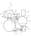
図1は、本発明の実施形態に係るターボ冷凍装置の全体図である。このターボ冷凍装置1は、冷媒を圧縮するターボ圧縮機2と、凝縮器3と、高圧膨張弁4と、中間冷却器5と、低圧膨張弁6と、蒸発器7と、潤滑油タンク8と、回路箱9と、インバータユニット10と、操作盤11等を備えてユニット状に構成されている。潤滑油タンク8は、ターボ圧縮機2の軸受や増速器等に供給する潤滑油を貯留するタンクである。
Embodiments of the present invention will be described below with reference to the drawings.
FIG. 1 is an overall view of a turbo refrigeration apparatus according to an embodiment of the present invention. The
凝縮器3と蒸発器7は耐圧性の高い円胴シェル形状に形成され、その軸線を略水平方向に延在させた状態で互いに隣り合うように平行に配置されている。凝縮器3は蒸発器7よりも相対的に高い位置に配置され、その下方に回路箱9が設置されている。中間冷却器5と潤滑油タンク8は、凝縮器3と蒸発器7との間に挟まれて設置されている。インバータユニット10は凝縮器3の上部に設置され、操作盤11は蒸発器7の上方に配置されている。
The
ターボ圧縮機2は、電動機13によって回転駆動される公知の遠心タービン型のものであり、その軸線を略水平方向に延在させた姿勢で蒸発器7の上方に配置されている。電動機13はインバータユニット10によって駆動される。ターボ圧縮機2は後述するように蒸発器7から吸入管14を経て供給される気相状の冷媒を圧縮する。冷媒としては、例えば最高圧力0.2MPaG未満で使用されるR1233zd等の低圧冷媒が用いられる。
The
ターボ圧縮機2の吐出口と凝縮器3の上部に設けられた冷媒入口22との間が吐出管15により接続され、凝縮器3の底部に設けられた冷媒出口23と中間冷却器5の底部との間が冷媒管16により接続されている。また、中間冷却器5の底部と蒸発器7との間が冷媒管17により接続され、中間冷却器5の上部とターボ圧縮機2の中段との間が冷媒管18により接続されている。冷媒管16には高圧膨張弁4が設けられ、冷媒管17には低圧膨張弁6が設けられている。
The
以上のように構成されたターボ冷凍装置1において、ターボ圧縮機2は電動機13に回転駆動され、蒸発器7から吸入管14を経て供給される気相状の低圧冷媒を圧縮し、この圧縮された低圧冷媒を吐出管15から凝縮器3に送給する。
In the
凝縮器3の内部では、ターボ圧縮機2で圧縮された高温の低圧冷媒が、水等の冷却液と熱交換されることにより凝縮熱を冷却されて凝縮液化される。ここで加熱された冷却液が暖房用の熱媒等として利用される。凝縮器3で液相状になった低圧冷媒は、凝縮器3から延出する冷媒管16に設けられた高圧膨張弁4を通過することにより膨張し、気液混合状態となって中間冷却器5に給送され、ここに一旦貯留される。
Inside the
中間冷却器5の内部では、高圧膨張弁4にて膨張した気液混合状態の低圧冷媒が気相分と液相分とに気液分離される。ここで分離された低圧冷媒の液相分は、中間冷却器5の底部から延出する冷媒管17に設けられた低圧膨張弁6によりさらに膨張して気液二相流となって蒸発器7に給送される。また、中間冷却器5で分離された低圧冷媒の気相分は、中間冷却器5の上部から延出する冷媒管18を経てターボ圧縮機2の中段部に給送され、再び圧縮される。
Inside the
蒸発器7の内部では、低圧膨張弁6において断熱膨張した後の低温の液冷媒が水等の被冷却液と熱交換され、ここで冷却された被冷却液は空調用の冷熱媒や工業用冷却液として利用される。被冷却液との熱交換により気化した冷媒は、吸入管14を経て再びターボ圧縮機2に吸入されて圧縮され、以下、このサイクルが繰り返される。
Inside the
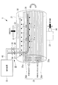
図2は、本発明の一実施形態を示す凝縮器3の斜視透視図である。
凝縮器3は、前述の通り水平方向に延在する円胴形状であり、最高圧力0.2MPaG未満で使用される低圧冷媒が導入されるシェル容器21と、このシェル容器21の上部に設けられた冷媒入口22と、シェル容器21の下部に設けられた冷媒出口23と、シェル容器21の内部において長手軸方向に沿って水平に延在する伝熱管束25と、本発明の要部となる抽気システム30と、を備えて構成されている。
FIG. 2 is a perspective perspective view of the
The
冷媒入口22と冷媒出口23は、それぞれシェル容器21の長手軸方向中間部に配置されている。図1に示すように、冷媒入口22は吐出管15を介してターボ圧縮機2の吐出口に接続され、冷媒出口23は冷媒管16を介して中間冷却器5に接続されている。
The
伝熱管束25は、シェル容器21の内部における長手軸方向一端(図2中左端)から他端(図2中右端)まで水平に延びる往路管束25Aと、シェル容器21内部の長手軸方向他端において往路管束25Aに連通し、シェル容器21内部の長手軸方向他端から一端まで水平に戻る復路管束25Bとを備えている。往路管束25Aと復路管束25Bは、いずれも内部に水等の冷却液が流通される多数の伝熱管25aが図示しない複数の多孔状の伝熱管支持板に挿通されて束ねられた公知の管束構造を有するものである。
The heat
シェル容器21の内部において、往路管束25Aは下方、復路管束25Bは上方に配置されている。シェル容器21の他端(図2中右端)には図示しないUターン室が設けられており、往路管束25Aと復路管束25Bの端部はこのUターン室に繋がることにより相互に連通している。また、シェル容器21の一端(図2中左端)には、往路管束25Aの一端に繋がる図示しないノズル状の冷却水入口と、この冷却水入口の上に位置し、復路管束25Bの一端に繋がる図示しないノズル状の冷却水出口とが設けられている。
In the
伝熱管束25に流される冷却液は、冷却水入口より往路管束25Aの一端(図2中左端)から流入して他端(図2中右端)に流れ、Uターン室にてUターンした後、復路管束25Bの他端(図2中右端)から一端(図2中左端)に流れ、冷却水出口を経て排出される。一方、ターボ圧縮機2で圧縮された高温・高圧のガス冷媒は、冷媒入口22からシェル容器21内に入り、分配板27によってシェル容器21の長手軸方向に分散され、復路管束25B→往路管束25Aの順に接触することにより熱交換されて凝縮し、液冷媒となって冷媒出口23から排出される。
After the coolant flowing into the heat
本発明の要部となる抽気システム30は、低圧冷媒に混入されやすい空気等の不凝縮ガスを抽気するシステムであり、伝熱管束内抽気管31と、伝熱管束外抽気管32と、抽気装置33と、仕切弁34,35とを備えて構成されている。
The
伝熱管束内抽気管31は、伝熱管束25における復路管束25Bの束径方向中心領域に配置されるとともに、復路管束25Bの軸方向に並行する水平な管状をなし、その下面に複数の丸穴状の不凝縮ガス抽気孔31aが形成されたものである。伝熱管束内抽気管31の長さは、例えば復路管束25Bのほぼ全長に亘る長さとされているが、より短くしてもよい。伝熱管束内抽気管31の一端、もしくは中間部には、上方に延びる不凝縮ガス排出管37が繋がっている。本実施形態では、伝熱管束内抽気管31の一端が上方に向かって湾曲あるいは屈曲されてそのまま不凝縮ガス排出管37とされている。伝熱管束内抽気管31の他端は閉塞されている。不凝縮ガス排出管37はシェル容器21の周面を上方に貫通し、抽気装置33から延出する不凝縮ガス集合管40に仕切弁34を介して接続されている。
The
伝熱管束内抽気管31の管径は、例えば15mm〜20mm程度である。不凝縮ガス抽気孔31aは、例えば軸方向に沿って20cm程度の間隔で穿設されており、その孔径は、例えば5〜10mm程度である。この不凝縮ガス抽気孔31aの孔径が小さ過ぎると、液冷媒中に没した時に液冷媒の表面張力により液封されてしまう場合がある。逆に孔径が大き過ぎると液冷媒が不凝縮ガス抽気孔31aから伝熱管束内抽気管31内に流れ込みやすくなる。なお、不凝縮ガス抽気孔31aの孔形状は必ずしも丸穴状でなくてもよく、例えば角孔状、あるいは伝熱管束内抽気管31の軸方向に対して傾斜した長穴状、伝熱管束内抽気管31の軸方向に沿うスリット状等とすることも考えられる。
The tube diameter of the
また、伝熱管束内抽気管31の出口側(不凝縮ガス排出管37側)から入口側(先端側)に向かって不凝縮ガス抽気孔31aの孔径を順次大きくしてもよい。このように、吸引力の強い(圧力損失の小さい)出口側の孔径を小さくし、吸引力の弱い(圧力損失の大きい)入口側の孔径を大きくすることにより、伝熱管束内抽気管31の全長に亘って均一に不凝縮ガスを抽気することができる。
Further, the diameter of the non-condensable
一方、伝熱管束外抽気管32は、シェル容器21内の上部空間、即ち往路管束25Aの上方に配置されてシェル容器21の長手軸方向に沿って水平に延びる管状部材である。この伝熱管束外抽気管32の管径は、例えば伝熱管束内抽気管31と同径であり、その下面に伝熱管束内抽気管31の不凝縮ガス抽気孔31aと同様な不凝縮ガス抽気孔32aが穿設されている。この伝熱管束外抽気管32にも、上方に延びる不凝縮ガス排出管38が繋がっている。不凝縮ガス排出管38はシェル容器21の周面を上方に貫通し、抽気装置33から延出する不凝縮ガス集合管40に仕切弁35を介して接続されている。
On the other hand, the
抽気装置33は、シェル容器21中における冷媒中に混入した空気等の不凝縮性ガスを一部の冷媒ガスと共に抽気し、これを冷却することによって冷媒ガスのみを凝縮、液化させて不凝縮性ガスから分離するように構成された公知のものである。この抽気装置33が作動すると、所定の負圧が不凝縮ガス集合管40と不凝縮ガス排出管37,38とを経て伝熱管束内抽気管31と伝熱管束外抽気管32とに加わり、伝熱管束内抽気管31と伝熱管束外抽気管32とに形成された不凝縮ガス抽気孔31a,32aから、シェル容器21中の冷媒に混入している不凝縮性ガスが一部の冷媒ガスと共に抽気される。
The
前述のように、伝熱管束内抽気管31から延びる不凝縮ガス排出管37と、伝熱管束外抽気管32から延びる不凝縮ガス排出管38とが、それぞれ仕切弁34,35を介して抽気装置33から延出する不凝縮ガス集合管40に接続されている。抽気装置33は、仕切弁34または仕切弁35を開くことによって、伝熱管束内抽気管31と伝熱管束外抽気管32とから、それぞれ独立的に不凝縮ガスを抽気することができる。また、仕切弁34,35を両方とも開くことにより、伝熱管束内抽気管31と伝熱管束外抽気管32の両方から不凝縮性ガスを抽気することもできる。さらに、仕切弁34,35の開弁度を異ならせることにより、伝熱管束内抽気管31と伝熱管束外抽気管32の抽気の割合を異ならせることもできる。
As described above, the non-condensable
凝縮器3は以上のように構成されている。
この凝縮器3では、抽気装置33に接続されて、シェル容器21内の冷媒中に混入している空気等の不凝縮ガスを抽気する伝熱管束内抽気管31が、伝熱管束25(復路管束25B)の束径方向中心領域に配置され、伝熱管束25の軸方向に並行するように設けられている。本構成によれば、ターボ冷凍装置1の運転時に不凝縮ガスが最も多く分布して高濃度になる伝熱管束25の内部に伝熱管束内抽気管31が配置されているため、抽気装置33を作動させることにより、低圧冷媒に混入した不凝縮ガスを高い濃度で効果的に抽気することができる。これにより、不凝縮ガスの混入による凝縮効率の低下を抑制することができる。
The
In the
不凝縮ガスを含む冷媒ガスは複数の不凝縮ガス抽気孔31aから伝熱管束内抽気管31内に抽気されるが、不凝縮ガス抽気孔31aは伝熱管束内抽気管31の下面に形成されているため、凝縮された液冷媒が不凝縮ガス抽気孔31aに流入しにくくなっている。このため、凝縮された液冷媒が抽出されてしまうことによる凝縮効率の低下を抑制することができる。
Refrigerant gas containing non-condensable gas is extracted from the plurality of non-condensable
また、伝熱管束内抽気管31は、伝熱管束25を構成している往路管束25Aと復路管束25Bのうち、往路管束25Aよりも上方に位置するとともに、往路管束25Aよりも下流側であるためにガス冷媒の凝縮量が少ない復路管束25Bの束径方向中心領域に配置されている。このため、伝熱管束内抽気管31が液冷媒に浸される確率が低くなり、液冷媒が不凝縮ガス抽気孔31aから伝熱管束内抽気管31の内部に入って抽出されてしまうことを防止し、液冷媒の抽出による凝縮効率の低下を抑制することができる。
The
また、この凝縮器3は、伝熱管束25(25B)の外部、且つシェル容器21内の上部空間に配置される伝熱管束外抽気管32をさらに備えている。この伝熱管束外抽気管32は、抽気装置33に接続されるとともに、その下面に不凝縮ガス抽気孔32aが形成されている。そして、抽気装置33は、伝熱管束内抽気管31と、伝熱管束外抽気管32とから、それぞれ独立的に不凝縮ガスを抽気可能となっている。
The
本構成によれば、ターボ冷凍装置1の運転時に不凝縮ガスが最も多く分布する伝熱管束25(25B)の内部に伝熱管束内抽気管31が配置されていることに加え、ターボ冷凍装置1の停止時に不凝縮ガスが最も多く分布するシェル容器21内の上部空間に伝熱管束外抽気管32が配置されることになる。そして、抽気装置33は、伝熱管束内抽気管31と伝熱管束外抽気管32とから、それぞれ独立的に不凝縮ガスを抽気することができる。
According to this configuration, in addition to the arrangement of the heat transfer tube
このため、ターボ冷凍装置1の運転停止時にはシェル容器21内の上部空間に位置する伝熱管束外抽気管32から抽気を行い、ターボ冷凍装置1の運転時には伝熱管束25(25B)の内部に位置する伝熱管束内抽気管31から抽気を行うことができる。これにより、ターボ冷凍装置1の運転状態に拘わらず、常に不凝縮ガスを高い濃度で効果的に抽気し、不凝縮ガスの混入による凝縮効率の低下を抑制することができる。もちろん、伝熱管束内抽気管31と伝熱管束外抽気管32の両方から同時に抽気を行ってもよい。
For this reason, when the operation of the
以上に説明したように、本実施形態に係る凝縮器3、およびこの凝縮器3を備えたターボ冷凍装置1によれば、最高圧力0.2MPaG未満で使用される低圧冷媒を用いたターボ冷凍装置1において、低圧冷媒に混入した不凝縮ガスを高い濃度で効果的に抽気可能にし、凝縮効率の低下を抑制することができる。
As described above, according to the
なお、本発明は上記実施形態の構成のみに限定されるものではなく、適宜変更や改良を加えることができ、このように変更や改良を加えた実施形態も本発明の権利範囲に含まれるものとする。
例えば、上記実施形態では、伝熱管束内抽気管31と伝熱管束外抽気管32とが、それぞれ1本ずつ設けられているが、2本以上設けてもよい。また、上記実施形態では、伝熱管束内抽気管31が伝熱管束25の上部を構成する復路管束25Bの内部に配設されているが、伝熱管束25の下部を構成する往路管束25Aの内部に配設することも考えられる。
It should be noted that the present invention is not limited to the configuration of the above-described embodiment, and can be appropriately changed or improved. Embodiments with such changes and improvements are also included in the scope of the right of the present invention. And
For example, in the above-described embodiment, one heat transfer tube
1 ターボ冷凍装置
2 ターボ圧縮機
3 凝縮器
4,6 膨張弁
7 蒸発器
21 シェル容器
22 冷媒入口
23 冷媒出口
25 伝熱管束
25A 往路管束
25B 復路管束
25a 伝熱管
31 伝熱管束内抽気管
31a,32a 不凝縮ガス抽気孔
32 伝熱管束外抽気管
33 抽気装置
DESCRIPTION OF
Claims (4)
前記シェル容器の上部に設けられる冷媒入口と、
前記シェル容器の下部に設けられる冷媒出口と、
内部に冷却液を流通させる多数の伝熱管が束ねられ、前記シェル容器の内部に延在する伝熱管束と、
前記伝熱管束の束径方向中心領域に配置されるとともに、該伝熱管束の軸方向に並行する管状をなし、その下面に、前記低圧冷媒中に混在する不凝縮ガスを抽気する不凝縮ガス抽気孔が形成された伝熱管束内抽気管と、
前記伝熱管束内抽気管に接続されて前記不凝縮ガスを抽気する抽気装置と、
を備えた凝縮器。 A shell container into which a low-pressure refrigerant used at a maximum pressure of less than 0.2 MPaG is introduced;
A refrigerant inlet provided at an upper portion of the shell container;
A refrigerant outlet provided at a lower portion of the shell container;
A number of heat transfer tubes that circulate the coolant inside are bundled, and the heat transfer tube bundle extending inside the shell container;
A non-condensable gas that is arranged in the central region in the bundle radial direction of the heat transfer tube bundle, forms a tube parallel to the axial direction of the heat transfer tube bundle, and extracts the non-condensable gas mixed in the low-pressure refrigerant on the lower surface thereof An extraction pipe in the heat transfer tube bundle in which extraction holes are formed;
An extraction device connected to the extraction tube in the heat transfer tube bundle and extracting the non-condensable gas;
With condenser.
前記抽気装置は、前記伝熱管束内抽気管と、前記伝熱管束外抽気管とから、それぞれ独立的に前記不凝縮ガスを抽気可能である請求項1に記載の凝縮器。 And further comprising an extraction pipe outside the heat transfer tube bundle, which is disposed in the upper space in the shell container, the non-condensable gas extraction holes are formed on the lower surface thereof, and connected to the extraction device,
The condenser according to claim 1, wherein the extraction device is capable of extracting the non-condensable gas independently from the extraction tube in the heat transfer tube bundle and the extraction tube outside the heat transfer tube bundle.
前記伝熱管束は、前記シェル容器の内部における長手軸方向一端から他端まで延びる往路管束と、前記シェル容器の内部における長手軸方向他端において前記往路管束に連通し、前記シェル容器の内部における長手軸方向他端から一端まで戻る復路管束と、を具備し、
前記シェル容器の内部において前記往路管束が下方、前記復路管束が上方に配置され、
前記伝熱管束内抽気管は、前記復路管束の束径方向中心領域に配置されている請求項1または2に記載の凝縮器。 The shell container has a cylindrical shape extending in a horizontal direction,
The heat transfer tube bundle communicates with the forward tube bundle extending from one end to the other end in the longitudinal axis inside the shell container, and the forward tube bundle at the other longitudinal end in the shell container, and inside the shell container A return pipe bundle returning from one end to the other in the longitudinal axis direction,
Inside the shell container, the forward tube bundle is disposed below, and the return tube bundle is disposed above,
The condenser according to claim 1 or 2, wherein the extraction pipe in the heat transfer pipe bundle is disposed in a bundle radial direction central region of the return pipe bundle.
圧縮された前記低圧冷媒を凝縮させる請求項1から3のいずれかに記載の凝縮器と、
凝縮した前記低圧冷媒を膨張させる膨張弁と、
膨張した前記低圧冷媒を蒸発させる蒸発器と、を具備してなるターボ冷凍装置。 A turbo compressor that compresses a low-pressure refrigerant used at a maximum pressure of less than 0.2 MPaG;
The condenser according to any one of claims 1 to 3, wherein the compressed low-pressure refrigerant is condensed.
An expansion valve for expanding the condensed low-pressure refrigerant;
And an evaporator for evaporating the expanded low-pressure refrigerant.
Priority Applications (4)
| Application Number | Priority Date | Filing Date | Title |
|---|---|---|---|
| JP2016081860A JP6821321B2 (en) | 2016-04-15 | 2016-04-15 | Condenser, turbo refrigeration system equipped with this |
| US16/076,477 US20190041100A1 (en) | 2016-04-15 | 2017-04-12 | Condenser, and centrifugal chiller equipped with the same |
| CN201780010490.5A CN108700354B (en) | 2016-04-15 | 2017-04-12 | Condenser and turbo refrigeration device equipped with the same |
| PCT/JP2017/015026 WO2017179631A1 (en) | 2016-04-15 | 2017-04-12 | Condenser, and turbo-refrigerating apparatus equipped with same |
Applications Claiming Priority (1)
| Application Number | Priority Date | Filing Date | Title |
|---|---|---|---|
| JP2016081860A JP6821321B2 (en) | 2016-04-15 | 2016-04-15 | Condenser, turbo refrigeration system equipped with this |
Publications (2)
| Publication Number | Publication Date |
|---|---|
| JP2017190927A true JP2017190927A (en) | 2017-10-19 |
| JP6821321B2 JP6821321B2 (en) | 2021-01-27 |
Family
ID=60042006
Family Applications (1)
| Application Number | Title | Priority Date | Filing Date |
|---|---|---|---|
| JP2016081860A Active JP6821321B2 (en) | 2016-04-15 | 2016-04-15 | Condenser, turbo refrigeration system equipped with this |
Country Status (4)
| Country | Link |
|---|---|
| US (1) | US20190041100A1 (en) |
| JP (1) | JP6821321B2 (en) |
| CN (1) | CN108700354B (en) |
| WO (1) | WO2017179631A1 (en) |
Cited By (1)
| Publication number | Priority date | Publication date | Assignee | Title |
|---|---|---|---|---|
| KR20190124962A (en) * | 2018-04-27 | 2019-11-06 | 한동대학교 산학협력단 | Method for improving condenser performance by reducing the effect of non-condensable gas and facility therefor |
Families Citing this family (4)
| Publication number | Priority date | Publication date | Assignee | Title |
|---|---|---|---|---|
| KR102868151B1 (en) * | 2020-05-08 | 2025-10-13 | 엘지전자 주식회사 | A turbo compressor and a turbo chiller including the same |
| CN111550938A (en) * | 2020-05-21 | 2020-08-18 | 武汉轻工大学 | Inner circulation water-saving solar water heater water pipe |
| KR20220068609A (en) * | 2020-11-19 | 2022-05-26 | 엘지전자 주식회사 | Condenser and Turbo chiller having the same |
| CN115371297A (en) | 2021-05-21 | 2022-11-22 | 开利公司 | Flow guide device for condenser, condenser with flow guide device and refrigeration system |
Citations (9)
| Publication number | Priority date | Publication date | Assignee | Title |
|---|---|---|---|---|
| JPS5420066U (en) * | 1977-07-12 | 1979-02-08 | ||
| JPS63104857U (en) * | 1986-12-18 | 1988-07-07 | ||
| JPH0325266A (en) * | 1989-06-23 | 1991-02-04 | Tokyo Gas Co Ltd | Air bleed device of air-cooled absorption type cold and hot water supplier |
| JPH0979708A (en) * | 1995-09-18 | 1997-03-28 | Osaka Gas Co Ltd | Plate fin condenser and absorber |
| JP2002048435A (en) * | 2000-07-31 | 2002-02-15 | Hitachi Zosen Corp | Absorption refrigerator |
| JP2003207284A (en) * | 2002-01-17 | 2003-07-25 | Mitsubishi Heavy Ind Ltd | Condenser and condensing method |
| JP2016023913A (en) * | 2014-07-24 | 2016-02-08 | 荏原冷熱システム株式会社 | Refrigerator condenser |
| WO2016035514A1 (en) * | 2014-09-05 | 2016-03-10 | 三菱重工業株式会社 | Turbo refrigeration machine |
| WO2016047305A1 (en) * | 2014-09-25 | 2016-03-31 | 三菱重工業株式会社 | Control device and control method for bleed device |
Family Cites Families (5)
| Publication number | Priority date | Publication date | Assignee | Title |
|---|---|---|---|---|
| US2321964A (en) * | 1941-08-08 | 1943-06-15 | York Ice Machinery Corp | Purge system for refrigerative circuits |
| JPS63104857A (en) * | 1986-10-22 | 1988-05-10 | Fujitsu Ltd | Image printer |
| US10579947B2 (en) * | 2011-07-08 | 2020-03-03 | Avaya Inc. | System and method for scheduling based on service completion objectives |
| JP5916360B2 (en) * | 2011-11-30 | 2016-05-11 | 三菱重工業株式会社 | Turbo refrigerator |
| JP6262040B2 (en) * | 2014-03-19 | 2018-01-17 | 三菱日立パワーシステムズ株式会社 | Condenser and turbine equipment |
-
2016
- 2016-04-15 JP JP2016081860A patent/JP6821321B2/en active Active
-
2017
- 2017-04-12 US US16/076,477 patent/US20190041100A1/en not_active Abandoned
- 2017-04-12 WO PCT/JP2017/015026 patent/WO2017179631A1/en not_active Ceased
- 2017-04-12 CN CN201780010490.5A patent/CN108700354B/en active Active
Patent Citations (9)
| Publication number | Priority date | Publication date | Assignee | Title |
|---|---|---|---|---|
| JPS5420066U (en) * | 1977-07-12 | 1979-02-08 | ||
| JPS63104857U (en) * | 1986-12-18 | 1988-07-07 | ||
| JPH0325266A (en) * | 1989-06-23 | 1991-02-04 | Tokyo Gas Co Ltd | Air bleed device of air-cooled absorption type cold and hot water supplier |
| JPH0979708A (en) * | 1995-09-18 | 1997-03-28 | Osaka Gas Co Ltd | Plate fin condenser and absorber |
| JP2002048435A (en) * | 2000-07-31 | 2002-02-15 | Hitachi Zosen Corp | Absorption refrigerator |
| JP2003207284A (en) * | 2002-01-17 | 2003-07-25 | Mitsubishi Heavy Ind Ltd | Condenser and condensing method |
| JP2016023913A (en) * | 2014-07-24 | 2016-02-08 | 荏原冷熱システム株式会社 | Refrigerator condenser |
| WO2016035514A1 (en) * | 2014-09-05 | 2016-03-10 | 三菱重工業株式会社 | Turbo refrigeration machine |
| WO2016047305A1 (en) * | 2014-09-25 | 2016-03-31 | 三菱重工業株式会社 | Control device and control method for bleed device |
Cited By (2)
| Publication number | Priority date | Publication date | Assignee | Title |
|---|---|---|---|---|
| KR20190124962A (en) * | 2018-04-27 | 2019-11-06 | 한동대학교 산학협력단 | Method for improving condenser performance by reducing the effect of non-condensable gas and facility therefor |
| KR102115080B1 (en) * | 2018-04-27 | 2020-05-25 | 한동대학교 산학협력단 | Method for improving condenser performance by reducing the effect of non-condensable gas and facility therefor |
Also Published As
| Publication number | Publication date |
|---|---|
| US20190041100A1 (en) | 2019-02-07 |
| WO2017179631A1 (en) | 2017-10-19 |
| JP6821321B2 (en) | 2021-01-27 |
| CN108700354A (en) | 2018-10-23 |
| CN108700354B (en) | 2021-07-23 |
Similar Documents
| Publication | Publication Date | Title |
|---|---|---|
| CN101576329B (en) | Self-overlapping refrigeration system | |
| ES2981856T3 (en) | Active/passive cooling system | |
| BR102019011251A2 (en) | COOLING SYSTEM USING CO2 FOR COOLING OF THE MAGNETIC COOLING SYSTEM | |
| CN108779943A (en) | Evaporator and the turbine refrigerating plant for having the evaporator | |
| US20170211851A1 (en) | Cooling system | |
| CN107560019A (en) | Dehumidifier | |
| WO2017179631A1 (en) | Condenser, and turbo-refrigerating apparatus equipped with same | |
| CN107850359A (en) | Evaporator and the turbine refrigerating plant for possessing the evaporator | |
| JP4118254B2 (en) | Refrigeration equipment | |
| US20180186216A1 (en) | Refrigeration cycle of vehicle air conditioner | |
| JP6670197B2 (en) | Condenser for compression refrigerator | |
| KR20110097367A (en) | Chiller | |
| JP2003240366A (en) | Refrigeration air conditioner | |
| JP3785143B2 (en) | Refrigerator evaporator and refrigeration equipment | |
| JP2008057807A (en) | Refrigeration cycle and air conditioner and refrigerator using the same | |
| KR102039488B1 (en) | Air conditioner | |
| JP2016023913A (en) | Refrigerator condenser | |
| KR101385194B1 (en) | A Condenser | |
| KR20090132938A (en) | Oil chiller and air conditioner including the same | |
| JP6456088B2 (en) | Radiator and refrigeration cycle device | |
| JP2002081777A (en) | Refrigeration cycle | |
| JP2021011985A (en) | Two-stage refrigerator | |
| JP6599176B2 (en) | Turbo refrigeration equipment | |
| CN109642760B (en) | Refrigerant distributor for falling film evaporator | |
| JP5485602B2 (en) | Refrigeration system |
Legal Events
| Date | Code | Title | Description |
|---|---|---|---|
| A711 | Notification of change in applicant |
Free format text: JAPANESE INTERMEDIATE CODE: A712 Effective date: 20170621 |
|
| A625 | Written request for application examination (by other person) |
Free format text: JAPANESE INTERMEDIATE CODE: A625 Effective date: 20190322 |
|
| A131 | Notification of reasons for refusal |
Free format text: JAPANESE INTERMEDIATE CODE: A131 Effective date: 20200204 |
|
| A601 | Written request for extension of time |
Free format text: JAPANESE INTERMEDIATE CODE: A601 Effective date: 20200406 |
|
| A02 | Decision of refusal |
Free format text: JAPANESE INTERMEDIATE CODE: A02 Effective date: 20200630 |
|
| A521 | Request for written amendment filed |
Free format text: JAPANESE INTERMEDIATE CODE: A523 Effective date: 20200928 |
|
| C60 | Trial request (containing other claim documents, opposition documents) |
Free format text: JAPANESE INTERMEDIATE CODE: C60 Effective date: 20200928 |
|
| A911 | Transfer to examiner for re-examination before appeal (zenchi) |
Free format text: JAPANESE INTERMEDIATE CODE: A911 Effective date: 20201006 |
|
| C21 | Notice of transfer of a case for reconsideration by examiners before appeal proceedings |
Free format text: JAPANESE INTERMEDIATE CODE: C21 Effective date: 20201013 |
|
| TRDD | Decision of grant or rejection written | ||
| A01 | Written decision to grant a patent or to grant a registration (utility model) |
Free format text: JAPANESE INTERMEDIATE CODE: A01 Effective date: 20201208 |
|
| A61 | First payment of annual fees (during grant procedure) |
Free format text: JAPANESE INTERMEDIATE CODE: A61 Effective date: 20210106 |
|
| R150 | Certificate of patent or registration of utility model |
Ref document number: 6821321 Country of ref document: JP Free format text: JAPANESE INTERMEDIATE CODE: R150 |