JP2017191683A - Storage device manufacturing method and storage device container cover plate - Google Patents
Storage device manufacturing method and storage device container cover plate Download PDFInfo
- Publication number
- JP2017191683A JP2017191683A JP2016079755A JP2016079755A JP2017191683A JP 2017191683 A JP2017191683 A JP 2017191683A JP 2016079755 A JP2016079755 A JP 2016079755A JP 2016079755 A JP2016079755 A JP 2016079755A JP 2017191683 A JP2017191683 A JP 2017191683A
- Authority
- JP
- Japan
- Prior art keywords
- lid plate
- container
- cover plate
- container body
- storage element
- Prior art date
- Legal status (The legal status is an assumption and is not a legal conclusion. Google has not performed a legal analysis and makes no representation as to the accuracy of the status listed.)
- Pending
Links
Images

Classifications
-
- Y—GENERAL TAGGING OF NEW TECHNOLOGICAL DEVELOPMENTS; GENERAL TAGGING OF CROSS-SECTIONAL TECHNOLOGIES SPANNING OVER SEVERAL SECTIONS OF THE IPC; TECHNICAL SUBJECTS COVERED BY FORMER USPC CROSS-REFERENCE ART COLLECTIONS [XRACs] AND DIGESTS
- Y02—TECHNOLOGIES OR APPLICATIONS FOR MITIGATION OR ADAPTATION AGAINST CLIMATE CHANGE
- Y02E—REDUCTION OF GREENHOUSE GAS [GHG] EMISSIONS, RELATED TO ENERGY GENERATION, TRANSMISSION OR DISTRIBUTION
- Y02E60/00—Enabling technologies; Technologies with a potential or indirect contribution to GHG emissions mitigation
- Y02E60/10—Energy storage using batteries
Landscapes
- Sealing Battery Cases Or Jackets (AREA)
- Gas Exhaust Devices For Batteries (AREA)
- Electric Double-Layer Capacitors Or The Like (AREA)
Abstract
【課題】容器本体と蓋板とが溶接により接合された容器を備える蓄電素子であって、品質が高い蓄電素子を製造するための製造方法を提供すること。【解決手段】容器本体101及び蓋板110を有する容器100を備える蓄電素子10の製造方法であって、所定方向に向けて凸のアーチ状の蓋板110を、容器本体101の開口102に対して、所定方向から押さえることで、蓋板110を押し広げる押さえ工程と、押さえ工程において押し広げられた蓋板110と、容器本体101とを溶接する溶接工程とを含む。【選択図】図5PROBLEM TO BE SOLVED: To provide a manufacturing method for manufacturing a high-quality power storage element, which is a power storage element including a container in which a container body and a cover plate are joined by welding. A method of manufacturing a power storage device 10 including a container 100 having a container body 101 and a lid plate 110, wherein an arch-shaped lid plate 110 that is convex in a predetermined direction is inserted into an opening 102 of the container body 101. Then, a pressing step for pressing and spreading the lid plate 110 by pressing from a predetermined direction, and a welding step for welding the lid plate 110 pressed and spread in the pressing step and the container body 101 are included. [Selection diagram] Fig. 5
Description
本発明は、容器を備える蓄電素子の製造方法、及び、蓄電素子の容器の蓋板に関する。 The present invention relates to a method for manufacturing a power storage element including a container, and a cover plate for the container of the power storage element.
従来、リチウムイオン二次電池などの蓄電素子は、例えば、容器と容器に収容された電極体とを備え、容器に配置された電極端子を介して充電及び放電する。 Conventionally, a storage element such as a lithium ion secondary battery includes, for example, a container and an electrode body accommodated in the container, and is charged and discharged via an electrode terminal disposed in the container.
このような構造の蓄電素子では、容器は、例えば、容器本体と蓋板とで構成されており、容器本体に電極体等の要素が収容された状態で、蓋板と容器本体の開口周縁とがレーザ溶接等によって接合される。具体的には、レーザ溶接では、蓋板と容器本体の開口とのつき合せ部分(境界部分)にレーザビームを照射することで当該部分の金属を溶融し、これにより、蓋板と容器本体とが接合される。 In the electricity storage device having such a structure, the container is composed of, for example, a container main body and a lid plate, and in the state in which an element such as an electrode body is accommodated in the container main body, Are joined by laser welding or the like. Specifically, in laser welding, the metal of the part is melted by irradiating a laser beam to the joining part (boundary part) of the lid plate and the opening of the container body. Are joined.
このような金属溶接が行われる場合、溶融した金属内で発生したガス、または溶融した金属内に侵入したガスが外部に放出されずに残存し、その結果、凝固した金属内に空洞(例えば「ブローホール」と呼ばれる。)が生じる場合がある。 When such metal welding is performed, the gas generated in the molten metal or the gas that has penetrated into the molten metal remains without being released to the outside, and as a result, a void (for example, “ Called "blowhole").
このような問題に対し、例えば特許文献1には、亜鉛系めっき鋼板を重ねレーザ溶接する場合において、2枚の鋼板の一方に凸部を設けることで、これら2枚の鋼板の間に所定の距離の隙間をあけ、これによりブローホールの発生を抑制できる旨が開示されている。 For such a problem, for example, in Patent Document 1, when a galvanized steel sheet is overlapped and laser-welded, a convex portion is provided on one of the two steel sheets so that a predetermined distance is provided between the two steel sheets. It is disclosed that a gap in the distance can be opened, thereby suppressing the occurrence of blow holes.
例えば、リチウムイオン二次電池の場合、容器の素材としては、一般に、アルミニウム合金等の、亜鉛系めっき鋼板とは異なる種類の金属が採用されており、この場合、上記従来の技術を適用することはできない。また、容器本体及び蓋板の互いに付き合わされる面の幅は狭いため、当該面に、所定の高さの微細な凸部を形成することは現実的ではない。 For example, in the case of a lithium ion secondary battery, the container material is generally a different type of metal from the zinc-based plated steel sheet, such as an aluminum alloy. In this case, the above-described conventional technique should be applied. I can't. Moreover, since the width | variety of the surface where a container main body and a cover plate mutually match | combine is narrow, it is not realistic to form the fine convex part of predetermined height in the said surface.
また、蓋板と容器本体との溶接を精度よく行うために、蓋板を容器本体の方向に押圧しながら溶接が行われるが、この時の押圧力が高すぎると、溶融した金属中のガスを逃すことができず、ブローホールが生じやすいという問題がある。また、当該押圧力が弱い場合は、例えば、蓋板に、容器本体の開口に沿わずに大きな隙間を形成する部分が生じ、その結果、溶接不良が発生するという問題が生じる。 Also, in order to accurately weld the lid plate and the container body, welding is performed while pressing the lid plate in the direction of the container body. If the pressing force at this time is too high, the gas in the molten metal There is a problem that blowholes are easily generated. Moreover, when the said pressing force is weak, the part which forms a big clearance gap in the cover plate not along the opening of a container main body, for example arises, As a result, the problem that a welding defect generate | occur | produces arises.
本発明は、上記従来の課題を考慮し、容器本体と蓋板とが溶接により接合された容器を備える蓄電素子であって、品質が高い蓄電素子を製造するための製造方法、及びその蓄電素子に用いられる蓋板を提供することを目的とする。 In view of the above-described conventional problems, the present invention is a power storage element including a container in which a container body and a cover plate are joined by welding, and a manufacturing method for manufacturing a high-quality power storage element, and the power storage element It aims at providing the cover plate used for.
上記目的を達成するために、本発明の一態様に係る蓄電素子の製造方法は、容器本体及び蓋板を有する容器を備える蓄電素子の製造方法であって、所定方向に向けて凸のアーチ状の蓋板を、前記容器本体の開口に対して、前記所定方向から押さえることで、前記蓋板を押し広げる押さえ工程と、前記押さえ工程において押し広げられた蓋板と、前記容器本体とを溶接する溶接工程とを含む。 In order to achieve the above object, a method for manufacturing a power storage device according to one aspect of the present invention is a method for manufacturing a power storage device including a container having a container body and a cover plate, and has a convex arch shape in a predetermined direction. By pressing the lid plate against the opening of the container body from the predetermined direction, and welding the lid plate, the lid plate spread in the pressing step, and the container body. Welding process.
この製造方法によれば、例えば容器本体の上部の開口に蓋板を溶接する場合、上方に凸にアーチ状の蓋板を、上方から押さえることで、例えば平坦となるように押し広げられ、その状態で溶接される。つまり、蓋板の弾性力によって、蓋板の両端部の間の部分(中間部)には、上方に向かおうとする反発力が生じ、かつ、アーチ状の蓋板の両端は容器本体に押し当てられる。その結果、蓋板の中間部が容器本体に対して過度に押圧されることを防止することができ、過度な押圧に起因する、ブローホール等の不具合の発生が抑制される。また、中間部が押さえられることで、両端部は容器本体に押し当てられるため、その結果、溶接時において、蓋板のズレ、または、蓋板の一部が容器本体から浮く等の問題が生じ難い。従って、容器本体と蓋板との接合の信頼性が向上され、その結果、信頼性の高い蓄電素子を得ることができる。 According to this manufacturing method, for example, when a lid plate is welded to the upper opening of the container body, the arch-shaped lid plate is convex upward and pressed from above, for example, to be flattened. Welded in a state. In other words, due to the elastic force of the lid plate, a repulsive force is generated in the portion (intermediate portion) between the both end portions of the lid plate, and both ends of the arched lid plate are pushed against the container body. Hit. As a result, it is possible to prevent the intermediate portion of the lid plate from being excessively pressed against the container body, and the occurrence of problems such as blow holes due to excessive pressing is suppressed. In addition, since both ends are pressed against the container body by pressing the intermediate part, as a result, a problem such as displacement of the cover plate or part of the cover plate floating from the container body occurs during welding. hard. Therefore, the reliability of joining the container body and the cover plate is improved, and as a result, a highly reliable power storage element can be obtained.
また、本発明の一態様に係る蓄電素子の製造方法において、蓋板には、長手方向の両端部の間の部分である中間部にガス排出弁が配置されているとしてもよい。 In the method for manufacturing a power storage element according to one embodiment of the present invention, the cover plate may include a gas discharge valve at an intermediate portion that is a portion between both end portions in the longitudinal direction.
この製造方法によれば、アーチ状の蓋板の、押さえ工程において押さえられる部分(つまり、中間部)と容器本体との接合部分について、溶接不良等の不具合の発生の可能性が低減され、これにより例えば、接合強度が向上する。そのため、ガス排出弁が配置されることで剛性が低下した蓋板の中間部の、容器の内圧に対する耐性を向上させることができる。 According to this manufacturing method, the possibility of occurrence of defects such as poor welding is reduced at the joint portion between the portion of the arch-shaped lid plate that is pressed in the pressing step (that is, the intermediate portion) and the container body. For example, the bonding strength is improved. Therefore, the tolerance with respect to the internal pressure of a container of the intermediate part of the cover board which rigidity reduced by having arrange | positioned a gas exhaust valve can be improved.
また、本発明の一態様に係る蓄電素子の製造方法において、前記押さえ工程では、前記蓋板の長手方向の少なくとも一方の端部は、前記蓋板が押さえられることで、前記開口の内側から前記開口の周縁に向けて移動するとしてもよい。 Further, in the method for manufacturing an energy storage device according to one aspect of the present invention, in the pressing step, at least one end portion in the longitudinal direction of the lid plate is pressed from the inside of the opening by pressing the lid plate. It may be moved toward the periphery of the opening.
この製造方法によれば、蓋板を容器本体の開口に配置する際に、蓋板の端部が、例えば開口の周縁に上方から衝突するような事態が生じないため、このような衝突に起因する、微小金属片(異物)の発生が抑制される。 According to this manufacturing method, when the cover plate is disposed in the opening of the container body, the end of the cover plate does not collide with the peripheral edge of the opening from above, for example. The generation of minute metal pieces (foreign matter) is suppressed.
また、本発明の一態様に係る蓄電素子の容器の蓋板は、蓄電素子の容器が有する容器本体の平面開口を塞ぐための蓋板であって、前記容器本体とは反対側に向けて凸のアーチ状である。 Further, the lid plate of the container of the electricity storage device according to one aspect of the present invention is a lid plate for closing the planar opening of the container body included in the container of the electricity storage device, and projects toward the opposite side of the container body. It is arched.
この構成によれば、蓄電素子の製造時において、容器本体の上部の平面開口に蓋板を溶接する場合、上方に凸にアーチ状の蓋板を、上方から押さえることで、平坦となるように押し広げられ、その状態で溶接される。つまり、蓋板の弾性力によって、蓋板の両端部の間の部分(中間部)には、上方に向かおうとする反発力が生じ、かつ、アーチ状の蓋板の両端は容器に押してられる。その結果、蓋板の中間部が容器本体に対して過度に押圧されることを防止することができ、過度な押圧に起因する、ブローホール等の不具合の発生が抑制される。また、中間部が押さえられることで、両端部は容器本体に押し当てられるため、その結果、溶接時において、蓋板のズレ、または、蓋板の一部が容器本体から浮く等の問題が生じ難い。従って、容器本体と蓋板との接合の信頼性が向上され、その結果、信頼性の高い蓄電素子を得ることができる。 According to this configuration, when the lid plate is welded to the flat opening at the top of the container body at the time of manufacturing the electric storage element, the arch-shaped lid plate is convex upward and pressed down from above to be flat. It is spread and welded in that state. In other words, due to the elastic force of the lid plate, a repulsive force is generated in the portion (intermediate portion) between both ends of the lid plate, and both ends of the arch-shaped lid plate are pushed by the container. . As a result, it is possible to prevent the intermediate portion of the lid plate from being excessively pressed against the container body, and the occurrence of problems such as blow holes due to excessive pressing is suppressed. In addition, since both ends are pressed against the container body by pressing the intermediate part, as a result, a problem such as displacement of the cover plate or part of the cover plate floating from the container body occurs during welding. hard. Therefore, the reliability of joining the container body and the cover plate is improved, and as a result, a highly reliable power storage element can be obtained.
本発明によれば、容器本体と蓋板とが溶接により接合された容器を備える蓄電素子であって、品質が高い蓄電素子を製造することができる。また、本発明によれば、その蓄電素子に用いられる蓋板を提供することができる。 ADVANTAGE OF THE INVENTION According to this invention, it is an electrical storage element provided with the container by which the container main body and the cover plate were joined by welding, Comprising: An electrical storage element with high quality can be manufactured. Moreover, according to this invention, the cover plate used for the electrical storage element can be provided.
以下、図面を参照しながら、本発明の実施の形態に係る蓄電素子について説明する。なお、各図は、模式図であり、必ずしも厳密に図示したものではない。 Hereinafter, a power storage device according to an embodiment of the present invention will be described with reference to the drawings. Each figure is a schematic diagram and is not necessarily illustrated exactly.
また、以下で説明する実施の形態は、本発明の一具体例を示すものである。以下の実施の形態で示される形状、材料、構成要素、構成要素の配置位置及び接続形態、製造工程の順序などは、一例であり、本発明を限定する主旨ではない。また、以下の実施の形態における構成要素のうち、最上位概念を示す独立請求項に記載されていない構成要素については、任意の構成要素として説明される。 The embodiment described below shows a specific example of the present invention. The shapes, materials, constituent elements, arrangement positions and connection forms of the constituent elements, order of manufacturing steps, and the like shown in the following embodiments are merely examples, and are not intended to limit the present invention. In addition, among the constituent elements in the following embodiments, constituent elements that are not described in the independent claims indicating the highest concept are described as optional constituent elements.
まず、図1及び図2を用いて、実施の形態に係る蓄電素子10の全般的な説明を行う。
First, with reference to FIG. 1 and FIG. 2, a general description of the
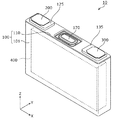
図1は、実施の形態に係る蓄電素子10の外観を示す斜視図である。図2は、実施の形態に係る蓄電素子10が備える容器本体101及び蓋板110それぞれの溶接前の状態を示す斜視図である。なお、図2では、容器100に収容される電極体400等の要素の図示は省略されている。
FIG. 1 is a perspective view showing an external appearance of a
また、図1及び以降の図について、説明の便宜のため、Z軸方向を上下方向として説明しているが、実際の使用態様において、Z軸方向と上下方向とが一致しない場合もある。 For convenience of explanation, FIG. 1 and the subsequent drawings are described with the Z-axis direction as the vertical direction. However, in the actual usage, the Z-axis direction may not match the vertical direction.
蓄電素子10は、電気を充電し、また、電気を放電することのできる二次電池であり、より具体的には、リチウムイオン二次電池などの非水電解質二次電池である。蓄電素子10は、例えば、電気自動車(EV)、ハイブリッド電気自動車(HEV)またはプラグインハイブリッド電気自動車(PHEV)等に適用される。
The
また、蓄電素子10は、UPS(無停電電源装置)、自然エネルギー貯蔵用蓄電装置、電車等の回生エネルギー貯蔵用蓄電装置(車両の内部または外部に設置されるもの)、エンジン始動用蓄電装置、またはAGV(無人搬送車)等に適用されてもよい。
The
なお、蓄電素子10は、非水電解質二次電池には限定されず、非水電解質二次電池以外の二次電池であってもよいし、キャパシタであってもよい。また、蓄電素子10の形状に関しては、角型に限定されることなく、例えば円筒型などの他の形状であってもよい。
In addition, the
図1及び図2に示すように、蓄電素子10は、容器100と、正極端子200と、負極端子300とを備えている。また、容器100が有する容器本体101の内部には電極体400が収容されており、容器本体101の開口102を塞ぐように蓋板110が配置されている。なお、図1において、電極体400は、点線で描かれた直方体によって概念的に表されており、電極体400の形状及びサイズは、図1に示される形状およびサイズに限定されない。
As shown in FIGS. 1 and 2, the
容器100は、矩形筒状で底を備える容器本体101と、容器本体101の開口102を塞ぐように取り付けられる板状部材である蓋板110とで構成されている。また、容器100は、電極体400等を内部に収容後、蓋板110と容器本体101とが溶接されることにより、内部を密封する構造を有している。
The
具体的には、開口102を形成する容器本体101の端縁(図2における容器本体101の上端縁、以下「開口102を形成する端縁」という。)は、本実施の形態では、1つのXY平面内に配置されており、これにより、開口102は、容器本体101において、平面開口として存在する。本実施の形態では、この開口102に対して、容器本体101とは反対側に凸のアーチ状の蓋板110が押し広げられて溶接される。この溶接の工程については、図3〜図8を用いて後述する。なお「平面」という場合、完全な平面だけでなく略平面も含まれる。
Specifically, the edge of the
また、蓋板110及び容器本体101の素材としては、例えばステンレス鋼、アルミニウム、またはアルミニウム合金など溶接可能な金属が採用される。
Further, as the material of the
蓋板110の中間部には、ガス排出弁170が備えられている。ガス排出弁170は、容器100の内圧が上昇した場合に開放し、容器100の内部のガスを放出する安全機構として、蓄電素子10に備えられている。
A
なお、蓋板110の中間部とは、蓋板110の長手方向(本実施の形態ではX軸方向)の両端部の間の部分である。例えば、蓋板110の中間部は、蓋板110における正極端子200及び負極端子300の間の部分である、と規定することができる。また、蓋板110の中間部は、側面視(Y軸方向から見た場合)において、ガス排出弁170のX軸方向における全長を含む部分である、と規定することもできる。
The intermediate portion of the
電極体400は、正極板と負極板とセパレータとを備え、電気を蓄えることができる部材である。本実施の形態では、正極板及び負極板がセパレータを挟んで巻回されることで形成された巻回型の電極体400が蓄電素子10に備えられている。また、電極体400は、例えば、巻回軸が、蓋板110と容器本体101の底面とを結ぶ方向、つまり、本実施の形態におけるZ軸方向に平行となる姿勢で、容器本体101に収容されている。
The
正極端子200は、正極集電体(図示せず)を介して電極体400の正極と電気的に接続された電極端子である。負極端子300は、負極集電体(図示せず)を介して電極体400の負極と電気的に接続された電極端子である。つまり、正極端子200及び負極端子300は、電極体400に蓄えられている電気を蓄電素子10の外部空間に導出し、また、電極体400に電気を蓄えるために蓄電素子10の内部空間に電気を導入するための金属製の電極端子である。
The
また、正極端子200は、蓋板110に、絶縁性を有するガスケット125を介して取り付けられており、負極端子300は、蓋板110に、絶縁性を有するガスケット135を介して取り付けられている。また、蓋板110を挟んでガスケット125及び135それぞれの裏側(Z軸方向マイナス側)にも、図示しないガスケットが配置されている。
The
なお、蓄電素子10は、上記の構成要素の他、容器100内の空間を埋めるスペーサ、及び電極体400等を包み込む絶縁フィルムなどを備えてもよい。また、蓄電素子10の容器100の内部には電解液(非水電解質)などの液体が封入されているが、当該液体の図示は省略する。容器100に封入される電解液としては、蓄電素子10の性能を損なうものでなければその種類に特に制限はなく、様々なものを選択することができる。
In addition to the above-described components, the
ここで、蓋板110は、容器本体101に溶接される前の時点では、所定の方向(本実施の形態では上方(Z軸方向プラス側))に凸のアーチ状の形状を有しており、これにより、蓋板110と容器本体101との溶接箇所の信頼性が向上されている。このことを、図3〜図8を用いて説明する。
Here, the
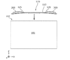
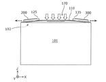
図3は、実施の形態に係る蓋板110の斜視図である。図4〜図7は、実施の形態に係る蓄電素子10の製造方法の一部を示す第1〜第4の図である。図8は、実施の形態に係る蓄電素子10の製造方法が含む押さえ工程の詳細を示す図である。なお、図4〜図8では、容器本体101に収容される電極体400等の要素、及び蓋板110の裏側に配置されたガスケット等の要素についての図示は省略されている。
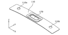
FIG. 3 is a perspective view of the
図3及び図4に示すように、実施の形態に係る蓋板110は、上方(容器本体101とは反対側)に凸のアーチ状である。つまり、実施の形態に係る蓋板110は、長手方向における、両端部の間の部分である中間部が上方に盛り上がるアーチ状(湾曲状)に形成されている。
As shown in FIGS. 3 and 4, the
また、蓋板110の中間部には、ガス排出弁170が設けられており、ガス排出弁170を挟んで2つの貫通孔110a及び110bが配置されている。
In addition, a
ガス排出弁170は、上述のように、容器100の内圧が上昇した場合に開放する機構であり、例えば、アーチ状の蓋板110を成形する際のプレス加工によって蓋板110に設けられる。具体的には、蓋板110の材料である金属板の一部がプレス加工によって薄肉化されることで、ガス排出弁170が形成される。なお、ガス排出弁の態様に特に限定はなく、例えば、蓋板110とは別体の金属板を、蓋板110に設けられた孔を塞ぐように配置することで、ガス排出弁が蓋板110に設けられてもよい。
As described above, the
貫通孔110aは、正極端子200の軸部を貫通させる孔であり、貫通孔110bは、負極端子300の軸部を貫通させる孔である。貫通孔110aを貫通した状態の正極端子200の軸部は、かしめ等によって正極集電体と接続される。貫通孔110bを貫通した状態の負極端子300の軸部は、かしめ等によって負極集電体と接続される。正極集電体は、電極体400の正極と溶接等によって接続され、負極集電体は、電極体400の負極と溶接等によって接続される。
The through
このようにして、電極体400と接続された蓋板110は、例えば、電極体400等の要素が容器本体101に収容されるとともに、開口102を塞ぐように配置される。
In this manner, the
つまり、蓋板110は、例えば、図4に示すように開口102の上方から開口102に向けて移動され、図5に示すように、開口102に載置され、さらに、所定の治具によって上方から押圧される。
That is, for example, the
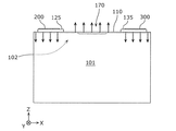
つまり、容器本体101とは反対側の方向(上方)に凸のアーチ状の蓋板110の中間部に対し、容器本体101の方向(下方)への押圧力が作用する。その結果、蓋板110は、図5及び図6に示すように、押し広げられる(押さえ工程)。
That is, a pressing force in the direction (downward) of the
ここで、アーチ状の蓋板110は、弾性変形しながら押し広げられるため、蓋板110の、押圧力が作用する中間部では、上方への反発力が生じる。なお、図6では、上向きの点線矢印により上方への反発力を模式的に表している。
Here, since the arch-shaped
そのため、例えば蓋板110の中間部が、容器本体101の開口102(より詳細には、開口102を形成する端縁)に近接または接触する程度に、蓋板110を押さえることで、蓋板110の中間部の、開口102を形成する端縁に対する押圧力を、ほぼゼロまたはごく低い値とすることができる。つまり、蓋板110の、押さえられる部分である中間部が、容器本体101に対して、過度に押圧されることなく、かつ、適切な溶接が可能な程度に近接または接触した状態が作り出される。
Therefore, for example, the
なお、蓋板110の中間部の、開口102を形成する端縁に対する押圧力が、ほぼゼロまたはごく低い値となる状態を実現するために、押さえ工程における蓋板110を押さえる力が実験等によって決定されてもよい。
In order to realize a state in which the pressing force of the intermediate portion of the
さらに、蓋板110の、中間部の両側の端部(両端部)のそれぞれは、直接的には、押圧されていないが、中間部が下方に押さえられることで生じる蓋板110の弾性力によって、開口102を形成する端縁に押し当てられる。これにより、蓋板110の両端部についても適切な溶接が可能な状態が形成される。なお、図6では、下向きの点線矢印により下方への弾性力を模式的に表している。
Furthermore, each of the end portions (both end portions) on both sides of the intermediate portion of the
また、押さえ工程における蓋板110の弾性変形の前後において、蓋板110に配置された正極端子200及び負極端子300と、電極体400との接続が問題なく維持されるように、当該接続には遊び(余裕)が持たされている。
In addition, before and after the elastic deformation of the
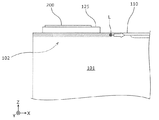
このように、蓋板110が、容器本体101の開口102に沿って押し広げられた状態で、蓋板110と容器本体101との溶接がなされる(溶接工程)。つまり、図7に示すように、蓋板110と容器本体101とのつき合せ部分(蓋板110と容器本体101との境界部分)に沿って、例えばレーザビームLが照射される。これにより、蓋板110が、容器本体101に溶接され、容器本体101の開口102が、蓋板110によって封止された状態が形成される。
In this manner, the
以上説明したように、本実施の形態に係る蓄電素子10の製造方法は、所定方向に向けて凸のアーチ状の蓋板110を、容器本体101の開口102に対して、当該所定方向から押さえることで、蓋板110を押し広げる押さえ工程と、押さえ工程において押し広げられた蓋板110と、容器本体101とを溶接する溶接工程とを含む。なお、本実施の形態に係る蓋板110は、蓄電素子10の容器100が有する容器本体101の平面開口である開口102を塞ぐための蓋板110であって、容器本体101とは反対側に向けて凸のアーチ状である、と表現できる。
As described above, in the method for manufacturing
本実施の形態では、容器本体101の上部に開口102が設けられており、上方に凸にアーチ状の蓋板110を上方から押さえることで、開口102に応じて平坦となるように押し広げられ、その状態で蓋板110と容器本体101とが溶接される。
In the present embodiment, an
つまり、蓋板110の弾性力によって、アーチ状の蓋板110の両端は容器本体101に押し当てられ、かつ、蓋板110の中間部には、上方に向かおうとする反発力が生じる。その結果、蓋板110の中間部が容器本体101に対して過度に押圧されることを防止することができる。これにより、蓋板110の中間部と容器本体101との溶接の際に、溶融した金属中のガスを逃しやすい環境が形成され、その結果、ブローホールの発生が抑制される。
That is, due to the elastic force of the
また、蓋板110の中間部が押さえられることで、蓋板110の両端部は弾性力によって容器本体101に押し当てられるため、溶接時において、蓋板110のズレ、または、蓋板110の一部が容器本体101から浮く等の問題が生じ難い。その結果、蓋板110の両端部についても、容器本体101と適切に溶接される。
In addition, since both ends of the
ここで、仮に、平板状の蓋板で容器本体101の開口102を塞ぐ場合、現実的には蓋板にランダムにゆがみが存在する場合もあり、このゆがみを矯正するためには、容器本体101との溶接の際に、蓋板の全体を比較的に大きな力で押さえる必要がある。このことはブローホール発生の要因となる。
Here, if the
しかしながら、本実施の形態では、上方に凸のアーチ状の蓋板110の中間部を押さえることで、蓋板110は、容器本体101の開口102に応じた形状になるように押し広げられる。これにより、例えば、蓋板110の全体を大きな力で押さえることなく、蓋板110と容器本体101との間の距離(0である場合も含む)を、蓋板110の周縁部の全域にわたって、溶接に適した距離にすることができる。
However, in the present embodiment, the
以上のように、本実施の形態に係る蓄電素子10の製造方法によれば、容器本体101と蓋板110とが溶接により接合された容器100を備える蓄電素子10であって、品質が高い蓄電素子10を製造することができる。
As described above, according to the method for manufacturing
また、本実施の形態において、蓋板110には、長手方向の両端部の間の部分である中間部にガス排出弁170が配置されている。
In the present embodiment, the
ガス排出弁170は、上述のように、例えば蓋板110の材料である金属板の一部が薄肉化されることで形成されるため、ガス排出弁170の配置領域は、蓋板110の中でも剛性が低い部分であるといえる。
As described above, the
その一方で、本実施の形態では、上述のように、アーチ状の蓋板110の、押さえ工程において押さえられる中間部と容器本体101との溶接箇所について、溶接不良等の不具合の発生の可能性が低減され、これにより例えば、接合強度が向上する。その結果、ガス排出弁170が配置されることで剛性が低下した蓋板110の中間部の、容器100の内圧に対する耐性を向上させることができる。このことは、例えば、ガス排出弁170の正常な動作の保証という観点からも重要である。
On the other hand, in the present embodiment, as described above, there is a possibility of occurrence of defects such as poor welding at the welding portion between the intermediate portion of the arch-shaped
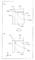
また、本実施の形態に係る蓄電素子10の製造方法では、より詳細には、押さえ工程において、蓋板110の長手方向の端部は、開口102の内側から周縁に向けて移動している。このことによる効果等について、図8を用いて説明する。
In the manufacturing method of
図8は、実施の形態に係る蓄電素子10の製造方法が含む押さえ工程の一部の詳細を説明する図である。なお、図8において、容器本体101の内部の要素は点線で図示されている。
FIG. 8 is a diagram illustrating the details of a part of the pressing step included in the method for manufacturing
本実施の形態に係る蓋板110は、上述のように、上方に凸のアーチ状であり、押さえ工程で押さえられた状態で、容器本体101の開口102が塞がれるサイズに設計及び製造されている。そのため、押さえ工程の前における、蓋板110の長手方向(本実施の形態ではX軸方向)の長さは、容器本体101のX軸方向の幅よりも小さい。より具体的には、押さえ工程の前における、蓋板110の、容器本体101の開口102に嵌められる嵌合部118のX軸方向における幅は、容器本体101の開口102のX軸方向の幅(X軸方向で対向する内面102a間の距離)よりも小さい。
As described above, the
そのため、例えば上述の図4及び図5に示すように、蓋板110を、容器本体101に対して配置する際に、蓋板110のX軸方向の中央と、容器本体101のX軸方向の中央とがほぼ一致するように配置され、その後、押さえ工程がなされる。
Therefore, for example, as shown in FIGS. 4 and 5 described above, when the
従って、図8の(a)及び(b)に示すように、蓋板110の端部111は、蓋板110が押さえられることで、開口102の内側から開口102の周縁102b(内面102aの上端)に向けて移動する。これにより、蓋板110の嵌合部118における角部118aと、開口102の周縁102bとが衝突することによる異物の発生が抑制される。
Therefore, as shown in FIGS. 8A and 8B, the
ここで、仮に、平板状の蓋板で容器本体101の開口102を塞ぐように配置した場合、蓋板の嵌合部における角部は、開口102の周縁102bに向けて上方から移動してくるため、嵌合部の角部と、開口102の周縁102bとが衝突する可能性がある。また、嵌合部の角部、及び、開口102の周縁102bは、いずれも板状の部材の角の部分であるため、これらが衝突した場合、ともに欠けやすい。すなわち、平板状の蓋板を、容器本体101の開口102を塞ぐように配置した場合、蓋板または容器本体101に欠けが生じる可能性、すなわち、異物としての微小な金属片が発生する可能性がある。このような微小な金属片は、例えば、電極体400における内部短絡の要因ともなる。また、蓋板の嵌合部の平面視(Z軸方向プラス側から見た場合)におけるサイズを小さくすることで、開口102の周縁102bと、嵌合部の角部との衝突を避けることも考えられるが、このような対策は、容器本体101に対する蓋板の位置規制という観点からは現実的ではない。
Here, if it is arranged so that the
この点に関して、本実施の形態では、蓋板110が、容器本体101に対して配置される際は、図8の(a)に示すように、蓋板110の嵌合部118の角部118aは、容器本体101の開口102の周縁102bからX軸方向に離れた位置に置かれる。そのため、蓋板110を容器本体101に対して配置する際において、金属部材同士が衝突することによる微小な金属片の発生は抑制される。
In this regard, in the present embodiment, when the
その後、上述のように、蓋板110の中間部が押さえられることで、蓋板110の形状は、開口102に沿って平坦にされる。この際、図8の(a)及び(b)に示すように、蓋板110の嵌合部118の角部118aは、容器本体101の開口102の内側から、周縁102bに向かって移動する。なお、図8の(a)及び(b)では、蓋板110の左側の端部111について図示しているが、蓋板110の右側の端部も同様に、容器本体101の開口102の内側から、右側の周縁に向かって移動する。このようにして、押し広げられた蓋板110は、蓋板110の嵌合部118が、容器本体101の内面102aに当接することで正規の位置からのずれが防止される。その後、図7を用いて説明したように、蓋板110と容器本体101と溶接される。
Thereafter, as described above, the intermediate portion of the
(他の実施の形態)
以上、本発明に係る蓄電素子について、実施の形態に基づいて説明した。しかしながら、本発明は、上記実施の形態に限定されるものではない。本発明の趣旨を逸脱しない限り、当業者が思いつく各種変形を上記実施の形態に施したものも、あるいは、上記説明された複数の構成要素を組み合わせて構築される形態も、本発明の範囲内に含まれる。
(Other embodiments)
The power storage element according to the present invention has been described based on the embodiments. However, the present invention is not limited to the above embodiment. Unless it deviates from the gist of the present invention, various modifications conceived by those skilled in the art have been applied to the above-described embodiments, or forms constructed by combining a plurality of the constituent elements described above are within the scope of the present invention. include.
例えば、上記実施の形態に係る蓋板110は、長手方向(X軸方向)における中間部が両端部よりも突出したアーチ状である。しかし、蓄電素子10が備える蓋板は、押さえ工程の前の状態において、短手方向(Y軸方向)における中間部が両端部よりも突出したアーチ状であってもよい。また、蓋板110は、平面視において略矩形状でなくてもよい。例えば、平面視において、楕円、円、長円形、または矩形以外の多角形など、略矩形以外の形状の蓋板が、蓄電素子が備える蓋板として採用されてもよい。
For example, the
つまり、容器本体とは反対側に凸のアーチ状の蓋板であれば、押さえ工程において、蓋板を容器本体の方向に押さえることで、蓋板を押し広げることができる。その結果、図6を用いて説明したように、蓋板に生じる弾性力(バネ力)を利用して、蓋板と容器本体とのつき合せ部分における適切な押圧状態を作り出すことができる。これにより、蓋板と容器本体との溶接部分におけるブローホールの発生は抑制される。 That is, if it is an arch-shaped cover plate convex on the side opposite to the container main body, the cover plate can be expanded by pressing the cover plate toward the container main body in the pressing step. As a result, as described with reference to FIG. 6, it is possible to create an appropriate pressing state at the portion where the lid plate and the container body are brought together by using the elastic force (spring force) generated in the lid plate. Thereby, generation | occurrence | production of the blowhole in the welding part of a cover plate and a container main body is suppressed.
また、ガス排出弁170が、蓋板110の中間部に配置されていることは必須ではない。長尺状の蓋板110における長手方向の中間部は、容器100の内圧が上昇した場合に、その内圧を受けて変位または変形が生じやすい部分である、ということもできる。そのため、蓋板110の中間部にガス排出弁170が存在していない場合であっても、上述のように、中間部において十分な接合強度を得ることで、蓄電素子10全体としての信頼性は向上される。
Further, it is not essential that the
また、蓋板110に、電極端子(200、300)が配置されていなくてもよい。つまり、容器本体101の5つの面のいずれかに電極端子(200、300)が配置されていてもよい。この場合であっても、蓋板110の、押さえ工程の前における形状がアーチ状であることによる、ブローホールの発生の抑制等の効果は奏される。
Further, the electrode terminals (200, 300) may not be disposed on the
また、蓄電素子10が備える巻回型の電極体400の姿勢に特に限定はない。例えば、巻回軸が、蓋板110の長手方向(X軸方向)に平行となる姿勢で、容器本体101に収容されていてもよい。
Further, there is no particular limitation on the posture of the
また、蓄電素子10が備える電極体は巻回型である必要はない。蓄電素子10は、例えば平板状極板を積層した積層型の電極体、または、長尺帯状の極板を山折りと谷折りとの繰り返しによって蛇腹状に積層した構造を有する電極体を備えてもよい。
In addition, the electrode body included in the
また、本発明は、上記説明された蓄電素子として実現することができるだけでなく、当該蓄電素子が備える蓋板として実現することができる。 In addition, the present invention can be realized not only as the power storage element described above but also as a cover plate included in the power storage element.
本発明は、リチウムイオン二次電池などの蓄電素子等に適用できる。 The present invention is applicable to power storage elements such as lithium ion secondary batteries.
10 蓄電素子
100 容器
101 容器本体
102 開口
102a 内面
102b 周縁
110 蓋板
110a、110b 貫通孔
111 端部
118 嵌合部
118a 角部
125、135 ガスケット
170 ガス排出弁
200 正極端子
300 負極端子
DESCRIPTION OF
Claims (4)
所定方向に向けて凸のアーチ状の蓋板を、前記容器本体の開口に対して、前記所定方向から押さえることで、前記蓋板を押し広げる押さえ工程と、
前記押さえ工程において押し広げられた蓋板と、前記容器本体とを溶接する溶接工程と
を含む蓄電素子の製造方法。 A method for producing an electricity storage device comprising a container having a container body and a cover plate,
A pressing step of expanding the lid plate by pressing the arch-shaped lid plate convex toward the predetermined direction against the opening of the container body from the predetermined direction;
A method for manufacturing an electricity storage element, comprising: a lid plate that is spread in the pressing step; and a welding step that welds the container body.
請求項1記載の蓄電素子の製造方法。 The method for manufacturing a power storage element according to claim 1, wherein a gas discharge valve is arranged in an intermediate portion that is a portion between both end portions in the longitudinal direction of the lid plate.
請求項1または2に記載の蓄電素子の製造方法。 3. The at least one end portion in the longitudinal direction of the lid plate moves from the inside of the opening toward the periphery of the opening when the lid plate is pressed in the pressing step. 4. A method for manufacturing a storage element.
前記容器本体とは反対側に向けて凸のアーチ状である
蓄電素子の容器の蓋板。 A lid plate for closing the planar opening of the container body of the container of the storage element,
A cover plate for a container of an electricity storage element, which has a convex arch shape facing away from the container body.
Priority Applications (1)
| Application Number | Priority Date | Filing Date | Title |
|---|---|---|---|
| JP2016079755A JP2017191683A (en) | 2016-04-12 | 2016-04-12 | Storage device manufacturing method and storage device container cover plate |
Applications Claiming Priority (1)
| Application Number | Priority Date | Filing Date | Title |
|---|---|---|---|
| JP2016079755A JP2017191683A (en) | 2016-04-12 | 2016-04-12 | Storage device manufacturing method and storage device container cover plate |
Publications (1)
| Publication Number | Publication Date |
|---|---|
| JP2017191683A true JP2017191683A (en) | 2017-10-19 |
Family
ID=60086398
Family Applications (1)
| Application Number | Title | Priority Date | Filing Date |
|---|---|---|---|
| JP2016079755A Pending JP2017191683A (en) | 2016-04-12 | 2016-04-12 | Storage device manufacturing method and storage device container cover plate |
Country Status (1)
| Country | Link |
|---|---|
| JP (1) | JP2017191683A (en) |
Cited By (3)
| Publication number | Priority date | Publication date | Assignee | Title |
|---|---|---|---|---|
| CN108628322A (en) * | 2018-07-09 | 2018-10-09 | 广东工业大学 | A kind of reliability degree calculation method and device of AGV path networks |
| JP2020119642A (en) * | 2019-01-18 | 2020-08-06 | トヨタ自動車株式会社 | Battery manufacturing method |
| US11640880B2 (en) | 2017-12-12 | 2023-05-02 | Gs Yuasa International Ltd. | Energy storage device |
-
2016
- 2016-04-12 JP JP2016079755A patent/JP2017191683A/en active Pending
Cited By (5)
| Publication number | Priority date | Publication date | Assignee | Title |
|---|---|---|---|---|
| US11640880B2 (en) | 2017-12-12 | 2023-05-02 | Gs Yuasa International Ltd. | Energy storage device |
| CN108628322A (en) * | 2018-07-09 | 2018-10-09 | 广东工业大学 | A kind of reliability degree calculation method and device of AGV path networks |
| CN108628322B (en) * | 2018-07-09 | 2021-08-13 | 广东工业大学 | Method and device for calculating reliability of AGV path network |
| JP2020119642A (en) * | 2019-01-18 | 2020-08-06 | トヨタ自動車株式会社 | Battery manufacturing method |
| JP7104885B2 (en) | 2019-01-18 | 2022-07-22 | トヨタ自動車株式会社 | Battery manufacturing method |
Similar Documents
| Publication | Publication Date | Title |
|---|---|---|
| JP6806217B2 (en) | Rechargeable battery | |
| JP7592983B2 (en) | Manufacturing method of electric storage element, and electric storage element | |
| US11407064B2 (en) | Energy storage device and method of manufacturing energy storage device | |
| KR20110035868A (en) | Secondary battery | |
| US20250201973A1 (en) | Energy storage device | |
| CN106252535A (en) | For the method manufacturing rectangular cell container with the end | |
| JP2017168349A (en) | Power storage device | |
| WO2019151359A1 (en) | Power storage element | |
| JP2016085875A (en) | Power storage device, power-supply module, and method for manufacturing power storage device | |
| JP6105986B2 (en) | Power storage device and method for manufacturing power storage device | |
| JP6701210B2 (en) | Electric storage element and method for manufacturing electric storage element | |
| JP5472671B2 (en) | Battery and manufacturing method thereof | |
| JP2017191683A (en) | Storage device manufacturing method and storage device container cover plate | |
| US20140023913A1 (en) | Prismatic secondary battery | |
| US11335956B2 (en) | Energy storage device and method of manufacturing energy storage device | |
| JP4259558B2 (en) | Battery and battery manufacturing method | |
| JP2017188337A (en) | Power storage element, lid body for container of power storage element, and power storage device | |
| JP6373590B2 (en) | Battery and battery manufacturing method | |
| JP6244781B2 (en) | Electrode body protection plate, power storage element, and method for manufacturing power storage element | |
| JP2019029116A (en) | Power storage element | |
| JP6764569B2 (en) | Sealed battery | |
| US20140134476A1 (en) | Energy storage device and method of producing the same | |
| JP7745583B2 (en) | Method for manufacturing an electricity storage device | |
| JP2019046803A (en) | Power storage element and power storage device | |
| JP7749299B2 (en) | Electricity storage device and method for manufacturing the same |