JP2017192953A - Method for manufacturing metal molded product and press molding apparatus - Google Patents
Method for manufacturing metal molded product and press molding apparatus Download PDFInfo
- Publication number
- JP2017192953A JP2017192953A JP2016083690A JP2016083690A JP2017192953A JP 2017192953 A JP2017192953 A JP 2017192953A JP 2016083690 A JP2016083690 A JP 2016083690A JP 2016083690 A JP2016083690 A JP 2016083690A JP 2017192953 A JP2017192953 A JP 2017192953A
- Authority
- JP
- Japan
- Prior art keywords
- mold
- press molding
- recess
- metal
- press
- Prior art date
- Legal status (The legal status is an assumption and is not a legal conclusion. Google has not performed a legal analysis and makes no representation as to the accuracy of the status listed.)
- Granted
Links
Images




Landscapes
- Forging (AREA)
- Shaping Metal By Deep-Drawing, Or The Like (AREA)
Abstract
【課題】ワークとして厚いものを使用しなくても、凹部の実質的な深さを確保できるようにすること。【解決手段】前段の工程において、プレス成形により金属ワーク40に複数の凹部22を形成するとともに、その凹部22の開口部の縁部にプレス方向の逆方向に突出する膨出部223を形成する。後段の工程において、前記凹部22内にその凹部22の内側面を受ける型を設置し、その状態で、プレス成形により前記膨出部223を圧潰して前記凹部22の開口部の縁部を整形する。【選択図】図8An object of the present invention is to ensure a substantial depth of a concave portion without using a thick work. In a first step, a plurality of recesses are formed in a metal work by press molding, and a bulging portion projecting in a direction opposite to a pressing direction is formed at an edge of an opening of the recess. . In a later step, a mold for receiving the inner surface of the recess 22 is set in the recess 22, and in this state, the bulging portion 223 is crushed by press molding to shape the edge of the opening of the recess 22. I do. [Selection diagram] FIG.
Description
本発明は、凹部を有する金属成形品の製造方法及びその製造方法に用いられるプレス成形装置に関するものである。 The present invention relates to a method for manufacturing a metal molded product having a recess, and a press molding apparatus used in the manufacturing method.
金属ワークに凹部を形成する場合には、プレス成形方法が採用される。ところが、このプレス成形方法においては、プレスの圧力により、凹部の開口部の縁部が、凹部内に引き込まれるようにして大きな円弧状に形成される。このため、凹部とその外側の部分との間の境界が不明瞭になり、凹部の実質的な深さが不足するおそれがある。従って、凹部を特定の目的に利用する場合、その凹部としての機能を有効に発揮し得ないおそれがある。従って、有効に機能する凹部を確保するためには、ワークとして厚さの厚いものを用いて、深い凹部を形成する必要がある。このようにすれば、当然ワークの重量も増し、金属成形品として好ましくないことが多い。 In the case of forming a recess in a metal workpiece, a press molding method is employed. However, in this press molding method, the edge of the opening of the recess is formed into a large arc shape by being pulled into the recess by the pressure of the press. For this reason, the boundary between a recessed part and the part of the outer side becomes obscure, and there exists a possibility that the substantial depth of a recessed part may be insufficient. Therefore, when using a recessed part for the specific objective, there exists a possibility that the function as the recessed part cannot be exhibited effectively. Therefore, in order to secure a concave portion that functions effectively, it is necessary to form a deep concave portion using a thick workpiece. If it does in this way, naturally the weight of a workpiece | work will increase and it is often unpreferable as a metal molded product.
このため、凹部の開口部の縁部をシャープエッジにすることにより、実質的に深い凹部が形成されるように、切削ツールを用いた切削方法または穿孔方法が採用されることもある。ところが、切削や穿孔による加工は、ひとつの凹部の加工に時間がかかることに加えて、全凹部の同時加工は困難である。従って、これらの加工方法は、加工効率が低い。さらに、切削や穿孔用のツールは加工によって摩耗しやすいために、ツールの頻繁な再研磨や交換を行なわないと、加工精度維持が難しい。加えて、ツールによって加工された部分からは無駄に廃棄される切屑が発生するため、材料の歩留まりが低下する問題もある。 For this reason, the cutting method or the drilling method using a cutting tool may be employ | adopted so that a deep deep recessed part may be formed by making the edge of the opening part of a recessed part into a sharp edge. However, machining by cutting or drilling takes time to process one recess, and simultaneously processing all recesses is difficult. Therefore, these processing methods have low processing efficiency. Furthermore, since cutting and drilling tools are easily worn by processing, it is difficult to maintain processing accuracy unless the tools are frequently reground or replaced. In addition, there is a problem in that the yield of the material is reduced because wastes that are wasted are generated from the portion processed by the tool.
特許文献1には、プレス成形により、ワークに対して凹部を形成する方法が開示されている。 Patent Document 1 discloses a method of forming a recess in a workpiece by press molding.
特許文献1においては、予備加工用ポンチの細ポンチ部が予備加工用ダイスのダイス孔に対応して設けられ、予備加工用ポンチの動作により、ワークに対して底部を有する有底凹状の予備孔が形成される。この予備孔は、ワークに対して打ち抜き加工を施す前の予備加工として形成されるものであって、加工精度や形状についてはほとんど考慮されていない。まして、薄いワークであっても、凹部の実質的な深さを得ようとすることには、配慮されていない。実際のところ、予備加工用ポンチの付け根部には、パンチング時の集中応力を緩和するための丸みを呈した応力緩和部分が設けられているため、前記予備孔の開口の縁部は、丸みを帯びてしまうことになり、前記のように、凹部とその外側の部分との間の境界が不明瞭になる。 In Patent Document 1, the narrow punch portion of the preliminary processing punch is provided corresponding to the die hole of the preliminary processing die, and a bottomed concave preliminary hole having a bottom portion with respect to the workpiece by the operation of the preliminary processing punch. Is formed. This preliminary hole is formed as preliminary processing before punching the workpiece, and the processing accuracy and shape are hardly considered. In addition, even a thin work is not considered to obtain a substantial depth of the recess. Actually, the base part of the punch for preliminary machining is provided with a stress relaxation part having a rounded shape for relaxing concentrated stress at the time of punching, so that the edge of the opening of the preliminary hole is rounded. As described above, the boundary between the concave portion and the outer portion becomes unclear.
本発明の目的は、このような問題点を解消するためになされたものであって、厚さの薄い金属ワークであっても、凹部として実質的な深さを十分に確保できる金属成形品の製造方法及びその製造方法に用いられるプレス成形装置を提供することにある。 An object of the present invention is to solve such problems, and it is a metal molded product that can sufficiently secure a substantial depth as a recess even in a thin metal workpiece. It is providing the manufacturing method and the press molding apparatus used for the manufacturing method.
上記目的を達成するために、本発明の金属成形品の製造方法は、前段の工程において、プレス成形により金属ワークに凹部を形成するとともに、その凹部の開口部の縁部にプレス方向の逆方向に突出する膨出部を形成し、後段の工程において、前記凹部内にその凹部の内側面を受ける整形型を設置し、その設置状態で、プレス成形により前記膨出部を圧潰して前記凹部の開口部の縁部を整形することを特徴とする。 In order to achieve the above object, the method for producing a metal molded product of the present invention includes forming a recess in a metal workpiece by press molding in the preceding step, and reversing the press direction at the edge of the opening of the recess. In the subsequent step, a shaping mold that receives the inner surface of the recessed portion is installed in the recessed portion, and in the installed state, the expanded portion is crushed by press molding to form the recessed portion. The edge of the opening is shaped.
また、本発明のプレス成形装置は、金属ワークをプレス成形するための前段プレス成形部及び後段プレス成形部を備えたプレス成形装置において、前記前段プレス成形部及び後段プレス成形部は、前記金属ワークを受けるための第1の金型と、その第1の金型上の金属ワークをプレスするための第2の金型とをそれぞれ備え、前記前段プレス成形部の第2の金型は、前記金属ワークに凹部を成形するための凹部成形型と、前記凹部の開口部の縁部にプレス方向の逆方向に突出する膨出部を成形するための膨出部成形型とを備え、前記後段プレス成形部の第2の金型は、前記膨出部を圧潰するための圧潰型と、その圧潰にともなって前記凹部の内側面を整形するための整形型とを備えたことを特徴とする。 Further, the press molding apparatus of the present invention is a press molding apparatus provided with a pre-stage press molding section and a post-stage press molding section for press-molding a metal workpiece, wherein the pre-stage press molding section and the post-stage press molding section are the metal workpiece. Each of the first mold for receiving the metal mold and the second mold for pressing the metal workpiece on the first mold, and the second mold of the pre-press forming section includes A recess forming die for forming a recess in the metal workpiece, and a bulging portion forming die for forming a bulging portion protruding in the opposite direction of the press direction at the edge of the opening of the recess, The second mold of the press-molding part includes a crushing mold for crushing the bulging part, and a shaping mold for shaping the inner side surface of the recess in accordance with the crushing. .
以上の方法及び構成によれば、凹部の縁部をシャープエッジ状に形成できる。このため、ワークとして厚いものを使用しなくても、凹部の実質的な深さを確保できる。また、凹部が複数であっても、複数の凹部を同時にプレス成形できて、高い加工効率を得ることができる。さらに、切削ツールを用いる必要がないため、ツール摩耗による精度低下を回避して、高い加工精度を維持できるとともに、廃棄される切屑が発生しないため、材料の歩留まりが低下することもない。 According to the above method and configuration, the edge of the recess can be formed in a sharp edge shape. For this reason, even if it does not use a thick thing as a workpiece | work, the substantial depth of a recessed part is securable. Moreover, even if there are a plurality of recesses, the plurality of recesses can be press-molded simultaneously, and high processing efficiency can be obtained. Further, since it is not necessary to use a cutting tool, it is possible to avoid a decrease in accuracy due to tool wear and maintain a high processing accuracy, and since no waste chips are generated, the yield of the material does not decrease.
本発明によれば、金属成形品に対して実質的に深い凹部を形成できる効果がある。 According to the present invention, there is an effect that a substantially deep recess can be formed in a metal molded product.
以下に、本発明を具体化した実施形態を図面に従って説明する。
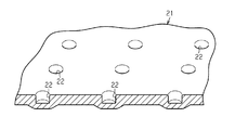
はじめに、金属成形品(以下、単に成形品という)21の構成を説明する。
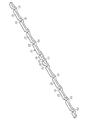
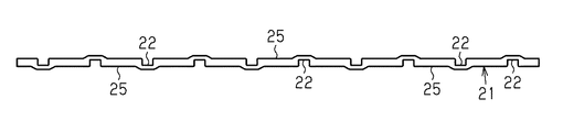
図3及び図4に示すように、成形品21はステンレススチールからなり、断面四角形で、長尺状に形成されている。成形品21の一側面には成形品21の厚さ方向に窪む複数(実施形態では10)の第1凹部22が成形品21の長さ方向に等間隔をおいて形成されている。隣接する一対の第1凹部22間の中間位置には第1凹部22と同じように厚さ方向に窪むひとつの第2凹部23が形成されている。この第2凹部23は、第1凹部22より深く形成されている。成形品21には、成形品21の両端部と、第1凹部22間に位置する第1フラット部25が形成されるとともに、第2凹部23の両側には一対の第2フラット部26が形成されている。第2フラット部26は、第1フラット部25より高い位置に配置されている。
DESCRIPTION OF EMBODIMENTS Embodiments embodying the present invention will be described below with reference to the drawings.
First, the configuration of a metal molded product (hereinafter simply referred to as a molded product) 21 will be described.
As shown in FIGS. 3 and 4, the
次に、前記成形品21の製造方法及びプレス成形装置について説明する。
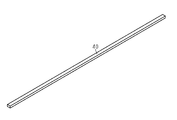
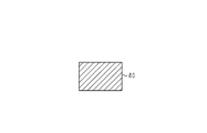
図1及び図2に示すように、成形品21となる前の金属ワーク(以下、単にワークという)40は、図示しない板材から切り出されたり、太材からダイスによって絞り成形されたりしたものであって、断面四角形に形成され、全体として棒状をなしている。
Next, a method for manufacturing the molded
As shown in FIGS. 1 and 2, a metal workpiece (hereinafter simply referred to as a workpiece) 40 before becoming a molded
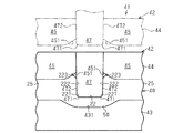
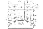
そして、前記第1凹部22及び第2凹部23が形成されるように、プレス成形装置41の図8及び図9に示す前段プレス成形部42と、図10及び図11に示す後段プレス成形部61とより、前記ワーク40が前後2回にわたってプレス成形される。従って、前段プレス成形部42により前段の工程が実行され、後段プレス成形部61により後段の工程が実行される。
Then, the first
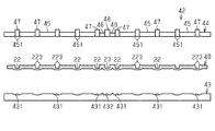
図5及び図6は、前段プレス成形部42によるプレス成形が終了した段階のワーク40を示す。そして、前記図3及び図4が、後段プレス成形部61によるプレス成形が終了した前記成形品21を示す。
5 and 6 show the
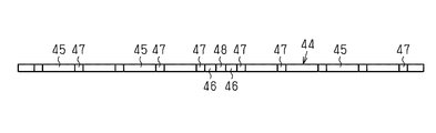
図5にはプレス成形装置41の前段プレス成形部42が示され、その前段プレス成形部42は、第1の金型としての下型43と、第2の金型としての上型44とを有する。下型43は固定位置にあり、上型44は昇降される。下型43には、等間隔をおいて複数箇所(実施形態では10箇所)の窪み部431と、一対の窪み部431間の1箇所に位置する窪み部432とが形成されている。
FIG. 5 shows a front
図5,図7,図8及び図9に示すように、上型44には、複数(実施形態では10、ただし両端のものは短い)の第1平面型45及び一対の第2平面型46が設けられている。また、上型44には凹部成形型を構成する複数(実施形態では10)の第1突出型47及びひとつの第2突出型48が設けられている。なお、本実施形態においては、図8〜図11における上下を装置の上下とする。ここで、図8及び図9に2点鎖線で示すように、上型44が上昇位置にあるときには、前記平面型45,46の下面と、前記突出型47,48の下面とはほぼ同じ高さにある。そして、図8及び図9に実線で示すように、上型44の下降に際して、平面型45,46の下降が停止された後も、突出型47,48は下降動作を行ない、平面型45,46の下方に突出される。
As shown in FIGS. 5, 7, 8, and 9, the
下型43の前記窪み部431,432は、第1,第2突出型47,48とそれぞれ対応する位置に形成されている。
図4,図10及び図11にはプレス成形装置41の後段プレス成形部61が示されている。この後段プレス成形部61は、第1の金型としての下型62と、第2の金型として上型63とを有する。下型62は固定位置にあり、上型63は昇降される。下型62には、複数箇所(実施形態では10箇所)の窪み部621と、一対の窪み部621間の1箇所に位置する窪み部622とが形成されている。上型63には圧潰型を構成する複数(実施形態では10、ただし両端のものは短い)の第1平面型64と、一対の第2平面型65とが設けられている。
The
4, FIG. 10 and FIG. 11 show a rear
また、上型63には成形型を構成する複数(実施形態では9)の第1突出型66及び一対の第2突出型67が設けられている。上型63の下面は、図7に示す上型44と同様に表われる。図10及び図11に2点鎖線で示すように、上型63が上昇位置にあるときには、前記平面型64,65の下面と、前記突出型66,67の下面とはほぼ同じ高さにあるが、上型63の下降に際して、平面型64,65の下降が停止された後も、突出型66,67は下降動作を行ない、平面型64,65の下方に突出される。
Further, the
下型62の前記窪み部621,622は、第1,第2突出型66,67とそれぞれ対応する位置に形成されている。
以上のように構成されたプレス成形装置41において、図8及び図9に示すように、前記ワーク40は、前段プレス成形のための前段プレス成形部42の下型43上にセットされる。
The
In the
そして、上型44の下降により、下型43上に定置されたワーク40が第1,第2平面型45,46及び第1,第2突出型47,48によってパンチングされる。このため、第1,第2突出型47,48によって第1,第2凹部22,23間の部分がプレス成形され、これと同時に、第1,第2平面型45,46により、第1,第2フラット部25,26が形成される。
When the
ここで、第1,第2突出型47,48と対応する位置において、下型43には窪み部431,432が形成されるため、パンチングによってワーク40の凹部22,23の底部側に凸部50,51が形成される。
Here, at the positions corresponding to the first and second projecting dies 47 and 48, the
前記第1,第2突出型47,48の先端部の両側部分には円弧状の曲面部471,481が形成されているため、凹部22,23の底部両側の内コーナ部には、曲面部471,481と同曲率の曲面部221,231が形成される。また、第1,第2突出型47,48の両側面472,482は上側にわずかに広がる傾斜面になっており、従って、凹部22,23の内側面222,232も上側に僅かに広がる傾斜状に形成されて、テーパ状になる。
Arc-shaped
前記第1平面型45の下面における第1突出型47側の縁部には第1突出型47側に上昇された斜面451が形成されている。このため、上型44のパンチングにともない、前記斜面451と第1突出型47の側面とにより、第1フラット部25の両端部,すなわち、第1フラット部25と隣接する第1凹部22の縁部である外コーナ部には、上方へ向かって、すなわちプレス方向の逆方向に向かって膨出部223が形成される。従って、斜面451を有する第1平面型45と第1突出型47とにより膨出部成形型が構成されている。
An
また、第2凹部23は、隣接する第1凹部22との間の狭い間隔内に形成されるため、第1凹部22と第2凹部23との間の第2フラット部26には、その全体が高く盛り上がる方向への応力が作用する。このため、第2平面型46の成形面が第1平面型45の成形面より高い位置に形成されて、第2凹部23間の第2フラット部26の上面は第1フラット部25の上面より高く形成される。ただし、第2平面型46には斜面は形成されておらず、第2凹部23の開口の縁部及び第1凹部22の第2凹部23側の縁部には前記膨出部223は形成されない。
Moreover, since the 2nd recessed
以上のようにしてプレス成形されたワーク40は、図10及び図11に示す後段プレス成形部61にセットされて、さらにプレス成形される。
そして、下型62上に定置されたワーク40に対して上型63の下降によるパンチングが行われると、第1,第2突出型66,67によってワーク40の第1,第2凹部22,23が整形されるとともに、第1,第2平面型64,65により第1,第2フラット部25,26が整形される。
The
When punching is performed on the
すなわち、前記第1平面型64の下面はフラットになっている。このため、前記フラット部25の膨出部223は第1平面型64のパンチングによる圧潰によってフラットになり、膨出部223を構成していた肉部は第1凹部22側に移動される。以上のように、膨出部223は圧潰されて、第1凹部22側に移動されるとともに、第1突出型66のパンチングによって第1凹部22の内部側に引き寄せられるが、第1突出型66の側面662で位置規制される。このため、第1凹部22の開口の縁部は先鋭状に形成される。言い換えれば、第1凹部22の開口部の縁部を構成する外コーナ部は曲率がきわめて大きな尖ったシャープエッジ状に整形され、よって、第1凹部22の内側面222の高さを高くすることができる。
That is, the lower surface of the first
一方、前記のように、第2凹部23は、隣接する第1凹部22間の狭い間隔内に形成されるため、第1凹部22と第2凹部23との間の第2フラット部26には、高く盛り上がる方向への応力が作用する。このため、前段プレス成形時と同様に、上型63の第2平面型65の成形面は高い位置に形成される。従って、第2フラット部26は第1フラット部25よりも高い位置において整形される。このため、第2凹部23の両内側面232及び第2凹部23の両側の一対の第1凹部22の第2フラット部26側の内側面222は、他の第1凹部22の内側面222より高く形成され、その状態で整形される。
On the other hand, as described above, since the
また、前記第1,第2突出型66,67の先端部の両側部分には前記曲面部471,481より曲率の大きな,言い換えれば曲率半径が短い円弧状の曲面部661,671が形成されているため、凹部22,23の底部両側における内コーナ部の曲面部221,231はほぼ直角の大曲率に形成される。さらに、第1,第2突出型66,67の両側面662,672は直立されており、第1凹部22の内側面222はテーパの拡開角度が小さい方向に整形されて、テーパ形状から互いに平行になる平面上に位置するように直立される。
In addition, arc-shaped
さらに、第1,第2平面型64,65により、第1,第2フラット部25,26の上面が平滑な平面となるように整形される。
後段のプレス成形による整形が終了した後、パンチングによってバリが生じている場合は、そのバリがカッターや砥石によって除去されて、成形品21となる。
Further, the first and second
In the case where burrs are generated by punching after shaping by the subsequent press molding, the burrs are removed by a cutter or a grindstone to form a molded
以上のようにして成形された成形品21は、例えば、複数の可動フィンを有するルーバー装置に用いられ、第1凹部22にフィンの一部が係入され、第2凹部23にアクチュエータの出力部が係入される。そして、アクチュエータの駆動により、成形品21が移動されると、全可動フィンの開き角度が一斉に調節される。
The molded
本実施形態においては、以下の効果がある。
(1)前段のプレス成形工程において、第1凹部22が形成されるとともに、その第1凹部22の開口部の縁部に膨出部223がプレス方向の逆方向に向かって形成される。そして、後段のプレス成形工程において前記膨出部223が圧潰されるとともに、第1凹部22の内側面が第2突出型67によって受けられて、第1凹部22の前記縁部がシャープエッジ状に整形される。従って、仮に、プレス成形によって第1凹部22の内部に向かって引き込まれる作用が働いても、膨出部223が形成されているため、第1凹部22の内側面を高く形成できる。このため、成形品21が薄いものであっても、深い第1凹部22を形成できる。従って、成形品21の軽量化を図ることができるとともに、第1凹部22の機能を有効に発揮できる。
The present embodiment has the following effects.
(1) In the preceding press molding step, the
(2)第2凹部23が隣接する第1凹部22間の狭い間隔内に形成されるため、第2凹部23と第1凹部22との間の第2フラット部26には盛り上がり方向への高い応力が作用する。このため、第2凹部23の両内側面232及びその両側の第1凹部22の第2フラット部26側の内側面222は高く形成される。その結果、深い第2凹部23を形成することができる。
(2) Since the second
(3)第1,第2凹部22,23がパンチングによって同時にプレス成形されるため、切削ツールで第1,第2凹部22,23を形成する場合と異なり、高い加工効率を得ることができる。しかも、切削ツールのような早期摩耗の問題が生じないため、長期間にわたる多数回加工を継続しても高精度加工が可能になる。加えて、廃棄される切屑が生じることはないため、ワーク材料の歩留まりを向上できる。
(3) Since the first and second
(4)ワーク40を前後2回にわけて第1,第2凹部22,23を成形するとともに、膨出部223を形成して、その膨出部223を圧潰することによってシャープエッジを形成するようにしているため、プレス圧力を格段に低くすることができて、装置のダメージを軽減できる。
(4) Forming the first and
(5)第1凹部22の形成と同時に膨出部223を形成し、その後、第1凹部22の整形時に膨出部223を圧潰させるように、前後2段に分けて第1凹部22を形成するため、ワーク40が硬い難加工材であっても、ワーク40が割れたり、プレス成形装置41にダメージが与えられたりするおそれを回避できる。
(5) The bulging
(6)前段のプレス成形工程において第1,第2凹部22,23の内コーナ部を曲面状に形成し、後段のプレス成形工程において内コーナ部の曲率を大きくするため、内コーナ部の曲率を無理なく大きくすることができて、第1,第2凹部22,23の内側面222,232の実質的な高さを高くすることができる。
(6) The inner corner portions of the first and
(7)前段のプレス成形工程において第1,第2凹部22,23の内側面222,232をワーク軸方向の外側に広がるテーパ状に形成し、後段のプレス成形工程において内側面222,232のテーパ拡開角度を小さくするため、その内側面222,232を直立させて、第1,第2凹部22,23を実質的に深くすることができる。
(7) The inner side surfaces 222 and 232 of the first and
なお、本発明は前記実施形態に限定されるものではなく、以下のような態様で具体化できる。
・前記実施形態では、前後2回に分けて、プレス成形するようにしたが、少なくとも前工程及び後工程の一方を複数段に分けて、全体として3回以上に分けてプレス加工すること。この場合、膨出部223は、複数回に分けて形成されたり、複数回に分けて圧潰されたりする。従って、パンチング1回当たりのプレス成形装置41の負担を軽減できる。
In addition, this invention is not limited to the said embodiment, It can be actualized with the following aspects.
-In the said embodiment, it divided into two times before and after, and it was press-molded, However, At least one of a pre-process and a post-process should be divided into several steps, and it should be divided into three or more times as a whole, and may be pressed. In this case, the bulging
・図10及び図11に2点鎖線で示すように、フラット部25,26の上面に浅い凹部70が形成されるようにすること。
・図12に示すように、成形品21に、第2凹部23及び第2フラット部26が形成されることなく、第1凹部22及び第1フラット部25のみが形成されるようにすること。この場合、図13に示すように、前段プレス成形部42及び後段プレス成形部61の第2突出型67及び第2平面型65は省略される。第2凹部23及び第2フラット部26が形成されていない成形品21は、例えば、図12に2点鎖線で示すように、一対の成形品21を第1凹部22が対向するように対称状に重ねることにより、対向する第1凹部22間を流体の通路にすることができる。
As shown by a two-dot chain line in FIGS. 10 and 11, a
As shown in FIG. 12, only the first
・第1凹部22が不等間隔で形成されるようにすること。
・棒状以外の形状、例えば、リング状や板状のワーク40を用いること。リング状のワーク40の場合は、そのワーク40の軸方向の端面に対して加工が施される。なお、リング状のワーク40は、パイプ材を輪切りすることによって得ることができる。
-The first recesses 22 should be formed at unequal intervals.
-Use a shape other than a rod shape, for example, a ring-shaped or plate-shaped
・図14に示すように、ワーク40の表裏両面に凹部23を形成すること。この場合、表裏の凹部23は、例えば交互配置のように規則的に配置されても、あるいは不規則に配置されても、いずれでもよい。
-As shown in FIG. 14, the recessed
・図15に示すように、板状のワーク40に穴状の凹部22が形成されるようにすること。
・ワーク40に対してあらかじめ面取りを施すこと。
-As shown in FIG. 15, the hole-shaped recessed
・ Chamfer the
・前段プレス成形部42の窪み部431,432を省略すること。
-Omit the recessed
21…金属成形品、22…第1凹部、23…第2凹部、40…金属ワーク、41…プレス成形装置、42…前段プレス成形部、61…後段プレス成形部、223…膨出部。
DESCRIPTION OF
Claims (8)
後段の工程において、前記凹部内にその凹部の内側面を受ける整形型を設置し、その設置状態で、プレス成形により前記膨出部を圧潰して前記凹部の開口部の縁部を整形する金属成形品の製造方法。 In the preceding step, a concave portion is formed in the metal workpiece by press molding, and a bulging portion protruding in the reverse direction of the pressing direction is formed at the edge of the opening of the concave portion,
In a subsequent step, a shaping mold that receives the inner surface of the recess is installed in the recess, and in the installed state, the bulging portion is crushed by press molding to shape the edge of the opening of the recess Manufacturing method of molded products.
前記前段プレス成形部及び後段プレス成形部は、前記金属ワークを受けるための第1の金型と、その第1の金型上の金属ワークをプレスするための第2の金型とをそれぞれ備え、
前記前段プレス成形部の第2の金型は、前記金属ワークに凹部を成形するための凹部成形型と、前記凹部の開口部の縁部にプレス方向の逆方向に突出する膨出部を成形するための膨出部成形型とを備え、
前記後段プレス成形部の第2の金型は、前記膨出部を圧潰するための圧潰型と、その圧潰にともなって前記凹部の内側面を整形するための整形型とを備えたプレス成形装置。 In a press molding apparatus provided with a former press molding part and a latter press molding part for press molding a metal workpiece,
The first-stage press molding section and the second-stage press molding section each include a first mold for receiving the metal workpiece and a second mold for pressing the metal workpiece on the first mold. ,
The second mold of the former press forming part is formed with a recessed part forming die for forming a recessed part in the metal work and a bulging part protruding in the opposite direction of the pressing direction at the edge of the opening part of the recessed part. And a bulging part mold for
The second mold of the latter press forming part includes a crushing mold for crushing the bulging part and a shaping mold for shaping the inner surface of the concave part in accordance with the crushing. .
Priority Applications (1)
| Application Number | Priority Date | Filing Date | Title |
|---|---|---|---|
| JP2016083690A JP6645334B2 (en) | 2016-04-19 | 2016-04-19 | Manufacturing method of metal molded product and press molding device |
Applications Claiming Priority (1)
| Application Number | Priority Date | Filing Date | Title |
|---|---|---|---|
| JP2016083690A JP6645334B2 (en) | 2016-04-19 | 2016-04-19 | Manufacturing method of metal molded product and press molding device |
Publications (2)
| Publication Number | Publication Date |
|---|---|
| JP2017192953A true JP2017192953A (en) | 2017-10-26 |
| JP6645334B2 JP6645334B2 (en) | 2020-02-14 |
Family
ID=60155258
Family Applications (1)
| Application Number | Title | Priority Date | Filing Date |
|---|---|---|---|
| JP2016083690A Active JP6645334B2 (en) | 2016-04-19 | 2016-04-19 | Manufacturing method of metal molded product and press molding device |
Country Status (1)
| Country | Link |
|---|---|
| JP (1) | JP6645334B2 (en) |
Citations (6)
| Publication number | Priority date | Publication date | Assignee | Title |
|---|---|---|---|---|
| JPS59193731A (en) * | 1983-04-18 | 1984-11-02 | Press Giken Kogyo Kk | Press die device for engraving groove |
| JPH08150428A (en) * | 1994-09-29 | 1996-06-11 | Nitto Kohki Co Ltd | A hole forming method for forming a through hole having a tapered shape in a workpiece by a press and a hole forming tool |
| JP2000237827A (en) * | 1999-02-17 | 2000-09-05 | Toyota Motor Corp | Die for embossing |
| JP2004017050A (en) * | 2002-06-12 | 2004-01-22 | Soode Nagano Co Ltd | Blind hole forming method |
| JP2004181502A (en) * | 2002-12-05 | 2004-07-02 | Jfe Steel Kk | Press working method excellent in shape freezing property and working tool used therefor |
| JP2007111725A (en) * | 2005-10-19 | 2007-05-10 | Nippon Steel Corp | Press molding method and press mold excellent in shape freezing property |
-
2016
- 2016-04-19 JP JP2016083690A patent/JP6645334B2/en active Active
Patent Citations (6)
| Publication number | Priority date | Publication date | Assignee | Title |
|---|---|---|---|---|
| JPS59193731A (en) * | 1983-04-18 | 1984-11-02 | Press Giken Kogyo Kk | Press die device for engraving groove |
| JPH08150428A (en) * | 1994-09-29 | 1996-06-11 | Nitto Kohki Co Ltd | A hole forming method for forming a through hole having a tapered shape in a workpiece by a press and a hole forming tool |
| JP2000237827A (en) * | 1999-02-17 | 2000-09-05 | Toyota Motor Corp | Die for embossing |
| JP2004017050A (en) * | 2002-06-12 | 2004-01-22 | Soode Nagano Co Ltd | Blind hole forming method |
| JP2004181502A (en) * | 2002-12-05 | 2004-07-02 | Jfe Steel Kk | Press working method excellent in shape freezing property and working tool used therefor |
| JP2007111725A (en) * | 2005-10-19 | 2007-05-10 | Nippon Steel Corp | Press molding method and press mold excellent in shape freezing property |
Also Published As
| Publication number | Publication date |
|---|---|
| JP6645334B2 (en) | 2020-02-14 |
Similar Documents
| Publication | Publication Date | Title |
|---|---|---|
| CN103212620B (en) | Impulse-free robustness blanking method and stamping-out system | |
| JP5325934B2 (en) | Piercing nut manufacturing equipment | |
| JP2007216293A (en) | Steel plate sprocket and manufacturing method thereof | |
| WO2017208669A1 (en) | Forging device | |
| CN105170833A (en) | Precise-punching and stretching forming method for gear ring | |
| KR20140114591A (en) | Press die | |
| CN106736305B (en) | A kind of thin plate punching weldering moulding manufacture method of clutch splined hub assembly | |
| JP2017524533A (en) | Cutlery manufacturing method and cutlery punching tool | |
| JP2009214108A (en) | Method of manufacturing closed-shape frame | |
| JP6645334B2 (en) | Manufacturing method of metal molded product and press molding device | |
| CN106132609A (en) | Method for producing through-holes in metal bodies by means of high-speed shearing | |
| CN105073296A (en) | Improved method for severed end surfaces | |
| JP2018020329A (en) | Forging processing device, forging processing method and manufacturing method of forging processing product | |
| CN114523031B (en) | Processing technology for cutting part without burr and product thereof | |
| JP2006159232A (en) | Thin plate cross-section molding method in press working method | |
| JP3583614B2 (en) | Gear manufacturing method | |
| CN206405289U (en) | A kind of mould for bending geometrical clamp | |
| CN214977125U (en) | Forming and punching composite die | |
| KR20180136729A (en) | Coining apparatus having punch adopting variable groove pin | |
| CN211027763U (en) | Side punching die | |
| JP2007090421A (en) | Burring processing mold and processing method | |
| JP4204601B2 (en) | Press machine and press method | |
| KR101480440B1 (en) | Making method of pan nut | |
| CN104907375A (en) | Volute wrapper sheet forming method and mold thereof | |
| CN104338858A (en) | Hardware part stamping die |
Legal Events
| Date | Code | Title | Description |
|---|---|---|---|
| A621 | Written request for application examination |
Free format text: JAPANESE INTERMEDIATE CODE: A621 Effective date: 20181018 |
|
| A977 | Report on retrieval |
Free format text: JAPANESE INTERMEDIATE CODE: A971007 Effective date: 20190805 |
|
| A131 | Notification of reasons for refusal |
Free format text: JAPANESE INTERMEDIATE CODE: A131 Effective date: 20190827 |
|
| A521 | Request for written amendment filed |
Free format text: JAPANESE INTERMEDIATE CODE: A523 Effective date: 20191028 |
|
| TRDD | Decision of grant or rejection written | ||
| A01 | Written decision to grant a patent or to grant a registration (utility model) |
Free format text: JAPANESE INTERMEDIATE CODE: A01 Effective date: 20191210 |
|
| A61 | First payment of annual fees (during grant procedure) |
Free format text: JAPANESE INTERMEDIATE CODE: A61 Effective date: 20191223 |
|
| R151 | Written notification of patent or utility model registration |
Ref document number: 6645334 Country of ref document: JP Free format text: JAPANESE INTERMEDIATE CODE: R151 |
|
| R250 | Receipt of annual fees |
Free format text: JAPANESE INTERMEDIATE CODE: R250 |
|
| R250 | Receipt of annual fees |
Free format text: JAPANESE INTERMEDIATE CODE: R250 |
|
| R250 | Receipt of annual fees |
Free format text: JAPANESE INTERMEDIATE CODE: R250 |
|
| R250 | Receipt of annual fees |
Free format text: JAPANESE INTERMEDIATE CODE: R250 |