JP2017192980A - Hot chamber casting equipment - Google Patents
Hot chamber casting equipment Download PDFInfo
- Publication number
- JP2017192980A JP2017192980A JP2016086624A JP2016086624A JP2017192980A JP 2017192980 A JP2017192980 A JP 2017192980A JP 2016086624 A JP2016086624 A JP 2016086624A JP 2016086624 A JP2016086624 A JP 2016086624A JP 2017192980 A JP2017192980 A JP 2017192980A
- Authority
- JP
- Japan
- Prior art keywords
- chamber
- molten metal
- plunger nozzle
- movable
- hot
- Prior art date
- Legal status (The legal status is an assumption and is not a legal conclusion. Google has not performed a legal analysis and makes no representation as to the accuracy of the status listed.)
- Granted
Links
Images


Landscapes
- Injection Moulding Of Plastics Or The Like (AREA)
- Molds, Cores, And Manufacturing Methods Thereof (AREA)
Abstract
Description
本発明は、アルミ等のダイキャスト品を製造するホットチャンバ鋳造装置に関する。 The present invention relates to a hot chamber casting apparatus for manufacturing a die-cast product such as aluminum.
アルミ合金を材料として製造されるダイキャスト品の鋳造法としては、比較的高温の溶湯(溶融金属材料)内で射出を行うホットチャンバ方式と、スリーブ内に溶湯を供給しながら射出を行うコールドチャンバ方式に大別される。これらのうちホットチャンバ方式においては、低圧射出により肉薄成型が可能であること、比較的融点が高い例えば純アルミの鋳造が可能であり鋳造金属材の選択範囲が広いなどのメリットがある。 There are two types of casting methods for die-cast products manufactured from aluminum alloys: a hot chamber system that performs injection in a relatively high temperature molten metal (molten metal material), and a cold chamber that performs injection while supplying molten metal into the sleeve. Broadly divided into methods. Among these, the hot chamber method has advantages such as being capable of thin molding by low-pressure injection, casting of pure aluminum having a relatively high melting point, for example, and a wide selection range of cast metal materials.
従来のホットチャンバ方式のアルミダイキャスト装置としては、例えば図6に示されるように縦型の射出チャンバが一般的である(例えば特許文献1、2参照)。この種の縦型チャンバは、主筒91内をプランジャ92が上下に摺動することにより、ポッド93に貯留するアルミ溶湯を枝筒94に加圧供給して鋳型95に溶融アルミを供給する構成である。
As a conventional hot chamber type aluminum die-casting apparatus, for example, a vertical injection chamber is generally used as shown in FIG. 6 (see, for example, Patent Documents 1 and 2). This type of vertical chamber has a configuration in which the
しかし、従来の縦型チャンバにおいては、主筒と枝筒との間にグースネックと称される湯路が鋭角に曲がる部分(例えば図6に示す湯路96)が存在する。そのため、装置のメンテナンス時には、グースネックを含む湯路内に残る溶湯の十分な湯抜きが必要である。また、主筒およびプランジャの摺動部分にアルミ溶湯表面に浮かぶ酸化物が付着する可能性もあり、それが射出金属材への不純物の混入やチャンバ装置の破損等の寿命低下の要因にもなっている。
However, in the conventional vertical chamber, there is a portion (for example, a
本発明は、このような従来の課題にかんがみてなされたものであり、従来よりも耐久性に優れ、更には射出金属材への不純物の混入を防ぐことができる等のホットチャンバ鋳造装置を提供することを目的としている。 The present invention has been made in view of such conventional problems, and provides a hot chamber casting apparatus that is superior in durability and that can prevent impurities from being mixed into an injection metal material. The purpose is to do.
上述した課題を解決するため、本発明のホットチャンバ鋳造装置は、溶融金属材料である溶湯を鋳型に射出する湯路が形成されたプランジャノズルと、前記プランジャノズルを嵌挿するチャンバ室を有し、前記プランジャノズルをチャンバ室内で進退させるように往復動することにより、溶湯を前記チャンバ室に導入しおよび前記プランジャノズルの湯路を介して射出する可動チャンバとを備え、前記可動チャンバが、前記プランジャノズル側を斜め上にして、少なくとも前記チャンバ室全体が前記溶湯内に浸漬した状態で設置されている。 In order to solve the above-described problems, a hot chamber casting apparatus of the present invention has a plunger nozzle in which a hot water passage for injecting a molten metal material into a mold is formed, and a chamber chamber into which the plunger nozzle is inserted. A movable chamber that reciprocates the plunger nozzle so as to advance and retreat in the chamber chamber, thereby introducing the molten metal into the chamber chamber and injecting the molten metal through the molten water passage of the plunger nozzle, and the movable chamber includes: The plunger nozzle side is obliquely upward, and at least the entire chamber chamber is installed in a state of being immersed in the molten metal.
この構成のホットチャンバ鋳造装置によれば、主要な射出構造が簡素化され、可動部におけるかじり等の破損を少なくして耐久性を増すことができる。また、射出湯路を斜めに配置したことで、低圧での鋳造が可能となる。更に、チャンバ室全体が溶湯内に浸漬した状態で設置されるため、溶湯表面に浮かぶ酸化物等の不純物の混入を防ぐことができる。 According to the hot chamber casting apparatus having this configuration, the main injection structure can be simplified, and damage such as galling in the movable part can be reduced to increase durability. In addition, since the injection hot water passage is arranged obliquely, casting at a low pressure becomes possible. Furthermore, since the entire chamber chamber is installed in a state of being immersed in the molten metal, it is possible to prevent impurities such as oxides floating on the surface of the molten metal from being mixed.
また、上記構成において、前記プランジャノズルが前記ポッドに設置される接合部分が前記溶湯のレベルよりも上にあることが好ましい。 Moreover, the said structure WHEREIN: It is preferable that the junction part in which the said plunger nozzle is installed in the said pod exists above the level of the said molten metal.
この構成によれば、プランジャノズルとポッドとの接合部分からの溶湯の漏れを防ぐために、従来のようなセラミックリング等で密にシールする必要がなくなり、装置を簡素化することができる。 According to this configuration, in order to prevent the molten metal from leaking from the joint portion between the plunger nozzle and the pod, it is not necessary to seal with a conventional ceramic ring or the like, and the apparatus can be simplified.
また、上記構成において、前記可動チャンバが往復動する動線と前記プランジャノズルの長手方向軸とが一致していることが好ましい。 Moreover, in the said structure, it is preferable that the flow line in which the said movable chamber reciprocates and the longitudinal direction axis | shaft of the said plunger nozzle correspond.
この構成によれば、主要な射出構造が簡素化され、かじり等の機械的な破損を少なくして耐久性を増すことができる。また、プランジャノズルと可動チャンバとを容易に分離することができ、メンテナンス性を向上させることができる。 According to this configuration, the main injection structure is simplified, mechanical damage such as galling is reduced, and durability can be increased. Further, the plunger nozzle and the movable chamber can be easily separated, and the maintainability can be improved.
また、上記構成において、前記プランジャノズルおよび可動チャンバが前記溶湯内で分離可能であり、且つ、これらが前記ポッドから取り外し可能に設置されていることが好ましい。 Moreover, in the said structure, it is preferable that the said plunger nozzle and a movable chamber are separable within the said molten metal, and these are installed so that removal from the said pod is possible.
この構成によれば、プランジャノズルと可動チャンバとを分離した状態で溶湯から引き上げることができるので、チャンバ室やプランジャノズルの湯抜きを十分に行うことができる。したがって、メンテナンス性を向上させることができる。 According to this configuration, since the plunger nozzle and the movable chamber can be separated from the molten metal, the chamber chamber and the plunger nozzle can be sufficiently drained. Therefore, maintainability can be improved.
本発明のホットチャンバ鋳造装置によれば、主要な射出構造を簡素化し、また低圧での鋳造を可能とした。これにより、従来よりも装置の耐久性が増し、長寿命化を図ることができる。また、チャンバを溶湯内に浸漬した構造であるので、溶湯表面の酸化物がチャンバに浸入せず、射出金属材への不純物の混入を防ぐことができる。 According to the hot chamber casting apparatus of the present invention, the main injection structure is simplified and casting at a low pressure is possible. As a result, the durability of the apparatus can be increased and the life can be extended as compared with the prior art. Further, since the chamber is immersed in the molten metal, the oxide on the surface of the molten metal does not enter the chamber, and contamination of the injected metal material can be prevented.
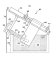
以下、図面を参照して、本発明に係るホットチャンバ鋳造装置の好適な実施形態を説明する。図1は、本発明の一実施形態によるホットチャンバ鋳造装置10の構成を示す側面図である。図2は、図1に示したホットチャンバ鋳造装置10の射出構造の主要部を示す断面図である。
DESCRIPTION OF EXEMPLARY EMBODIMENTS Hereinafter, a preferred embodiment of a hot chamber casting apparatus according to the invention will be described with reference to the drawings. FIG. 1 is a side view showing a configuration of a hot
ホットチャンバ鋳造装置10は、ポッド(溶湯槽)50内に貯留した溶融アルミなどの溶湯Wを、鋳型のキャビティ63に加圧射出することにより、所望形状の鋳造品を製造する装置である。
ポッド50は、図示しない溶湯保持炉に設置される耐熱槽である。本実施形態のポッド50は、例えば700℃以上の一定温度に溶湯を加熱保持することが可能である。また、ポッド50には、公知の溶解炉から高温の溶湯が適宜に補給され、溶湯レベルが一定に保持されている。
The hot
The
ホットチャンバ鋳造装置10により製造される鋳造品の金属材料としては、アルミ、アルミ合金(例えば、Al‐Si系、Al‐Si‐Cu系)、銅合金、マグネシウム合金、亜鉛合金などがある。特に、本ホットチャンバ鋳造装置10は、不純物の混入を防ぐことができ、また高温低圧での射出成型が可能である点において、例えば熱伝導率が高い純アルミを材料とする精密部品の鋳造に適している。
Examples of the metal material of a cast product manufactured by the hot
ホットチャンバ鋳造装置10は、鋳型61、62に溶湯Wを射出するプランジャノズル20と、駆動装置40により往復動するように設けられる可動チャンバ30とを備える。なお、本実施形態の鋳型は、固定金型61と可動金型62とが突き合わされて形成され、駆動装置40から垂下する支持部材60に取り付けられている。
The hot
プランジャノズル20は、耐熱性のあるセラミックにより形成され、ストレートに伸びる略円柱状を有している。プランジャノズル20の長手方向中心軸には、湯路21が貫かれて形成されている。プランジャノズル20のノズル先端部は、支持部材60を貫通し、固定金型61の注入路61bに連通する凹面部61aに圧接している。他方、プランジャノズル20の後端部は、可動チャンバ30の下部に形成されたチャンバ室31に嵌挿されている。
The
可動チャンバ30も耐熱性のあるセラミックにより形成される。可動チャンバ30には、上述したプランジャノズル20の後端部を嵌挿させるチャンバ室31が形成されている。チャンバ室31は、プランジャノズル20を進退可能に嵌挿できるように、プランジャノズル20の直径よりも若干が大きい直径を有する円形でストレートの深孔として形成される。また、可動チャンバ30には、チャンバ室31に連通する溶湯導入孔32およびガス抜き孔33が形成されている。溶湯導入孔32およびガス抜き孔33は、チャンバ室31への溶湯Wの導入、湯抜きおよびガス抜きのために設けられている。
The
可動チャンバ30の上部は駆動装置40に連結している。駆動装置40は、ベースプレート41上に、油圧シリンダ42、ブラケット46、47などを備えている。ガイドロッド45は、油圧シリンダ42の左右両側に2本、互いに平行に、前後のブラケット46、47に支持されている。また、2本の平行なガイドロッド45は、可動チャンバ30内を摺動可能に貫通しており、そのガイドする方向は、チャンバ室31の深さ方向、つまりプランジャノズル20の長手方向と一致している。
The upper part of the
可動チャンバ30は、その前面に固定されたジョイント44に、油圧シリンダ42のロッド43が接続している。油圧シリンダ42へ供給する圧油を切り換えてロッド43を伸長および縮退させることで、可動チャンバ30がガイドロッド45に案内されながら往復動する。なお、ガイドロッド45に案内される可動チャンバ30の動線は、チャンバ室31の深さ方向に一致するとともに、プランジャノズル20の長手方向軸も一致している。
The
このように、ホットチャンバ鋳造装置10は、可動チャンバ30の往復動作に連動して、プランジャノズル20の後端部がチャンバ室31内で進退動作するように構成されている。これら主要な射出構造が簡素化されることで、可動部のかじり等の機械的な故障が少なく、耐久性が増し、ひいては装置の長寿命化を図ることができる。
As described above, the hot
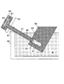
また、油圧シリンダ42は、プランジャノズル20と可動チャンバ30とを分離するのに十分なストロークを有していることが好ましい。そうすることにより、溶湯Wに浸漬させたまま、プランジャノズル20と可動チャンバ30の分離が可能となる。また、図3に示すように、プランジャノズル20と可動チャンバ30とを分離した状態で、クレーンなどでこれらを溶湯Wから引き上げることができるので、チャンバ室31や湯路21の湯抜きを十分に行うことができる。
The
ホットチャンバ鋳造装置10は、可動チャンバ30が、少なくともチャンバ室31全体を溶湯W内に浸漬させて支持フレーム70に設置されている。これにより、鋳造動作中に溶湯Wの表面に浮かぶ金属酸化物等がチャンバ室31に導入されず、射出金属材への不純物の混入を防止することができる。
In the hot
また、可動チャンバ30が往復動する動線が、射出側であるプランジャノズル20が上となるように、可動チャンバ30およびプランジャノズル20が斜めに配置されている。これにより、チャンバ室31を起点とする射出湯路が斜めとなり、従来の縦型に比較して低圧での鋳造を可能としている。
In addition, the
また、プランジャノズル20およびチャンバ室31の長手方向軸を斜め直線上に配置したことにより、プランジャノズル20がポッド50に設置される接合部分を溶湯Wのレベルよりも上にすることができる。これにより、ポッド50とプランジャノズル20との接合部分の溶湯の漏れを防ぐために、従来のようなセラミックリングで密にシールする必要がなくなる。
Further, by arranging the longitudinal axes of the
また、ポッド50の上端に形成した例えば受け溝51にプランジャノズル20の筒体を載置した簡素な接合構造により、装置のメンテナンス時にクレーンなどでプランジャノズル20をクレーンで引き上げて容易にこれらを取り外すことができる(図3参照)。これにより、ホットチャンバ鋳造装置10をメンテナンスする際の作業性を向上させることができる。
Further, for example, a simple joint structure in which the cylindrical body of the
かかる構成のホットチャンバ鋳造装置10による鋳造動作は次のとおりである。
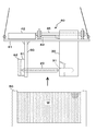
まず、チャンバ室31に溶湯Wを導入するため、図4に示すように、油圧シリンダ42のロッド43を伸長させ可動チャンバ30を押し下げる。このときチャンバ室31の容積が増し減圧されることにより、溶湯がチャンバ室31内面とプランジャノズル20の外面との間の隙間を介してチャンバ室31に導入される。
The casting operation by the hot
First, in order to introduce the molten metal W into the
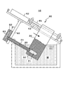
次に、図5に示すように、油圧シリンダ42のロッド43を縮退させ可動チャンバ30を引き上げる。これにより、チャンバ室31内が加圧され、溶湯がプランジャノズル20の湯路21を介して金型61、62間の空間であるキャビティ63に射出される。そして、キャビティ63内の溶湯が冷却固化した後、可動金型62を固定金型61から分離することで、所定形状の鋳造品が得られる。
Next, as shown in FIG. 5, the
10 ホットチャンバ鋳造装置
20 プランジャノズル
21 湯路
30 可動チャンバ
31 チャンバ室
32 溶湯導入孔
33 ガス抜き孔
40 駆動装置
42 油圧シリンダ
43 ロッド
44 ジョイント
45 ガイドロッド
50 ポッド(溶湯槽)
51 受け溝
60 支持部材
61 固定金型
62 可動金型
63 キャビティ
70 支持フレーム
W 溶湯
DESCRIPTION OF
51 receiving
Claims (4)
前記プランジャノズルを嵌挿するチャンバ室を有し、前記プランジャノズルをチャンバ室内で進退させるように往復動することにより、溶湯を前記チャンバ室に導入しおよび前記プランジャノズルの湯路を介して射出する可動チャンバとを備え、
前記可動チャンバが、前記プランジャノズル側を斜め上にして、少なくとも前記チャンバ室全体が前記溶湯内に浸漬した状態で設置されているホットチャンバ鋳造装置。 A plunger nozzle formed with a hot water passage for injecting a molten metal material into a mold;
The chamber has a chamber into which the plunger nozzle is inserted, and the plunger nozzle is reciprocated so as to advance and retreat in the chamber, thereby introducing the molten metal into the chamber chamber and injecting the molten metal through the water passage of the plunger nozzle. A movable chamber,
The hot chamber casting apparatus, wherein the movable chamber is installed with the plunger nozzle side obliquely upward and at least the entire chamber chamber is immersed in the molten metal.
The hot chamber casting apparatus according to any one of claims 1 to 3, wherein the plunger nozzle and the movable chamber are separable in the molten metal and are detachable from the pod.
Priority Applications (1)
| Application Number | Priority Date | Filing Date | Title |
|---|---|---|---|
| JP2016086624A JP6727903B2 (en) | 2016-04-23 | 2016-04-23 | Hot chamber casting equipment |
Applications Claiming Priority (1)
| Application Number | Priority Date | Filing Date | Title |
|---|---|---|---|
| JP2016086624A JP6727903B2 (en) | 2016-04-23 | 2016-04-23 | Hot chamber casting equipment |
Publications (2)
| Publication Number | Publication Date |
|---|---|
| JP2017192980A true JP2017192980A (en) | 2017-10-26 |
| JP6727903B2 JP6727903B2 (en) | 2020-07-22 |
Family
ID=60155113
Family Applications (1)
| Application Number | Title | Priority Date | Filing Date |
|---|---|---|---|
| JP2016086624A Active JP6727903B2 (en) | 2016-04-23 | 2016-04-23 | Hot chamber casting equipment |
Country Status (1)
| Country | Link |
|---|---|
| JP (1) | JP6727903B2 (en) |
-
2016
- 2016-04-23 JP JP2016086624A patent/JP6727903B2/en active Active
Also Published As
| Publication number | Publication date |
|---|---|
| JP6727903B2 (en) | 2020-07-22 |
Similar Documents
| Publication | Publication Date | Title |
|---|---|---|
| ES2803600T3 (en) | Apparatus and method for melting and casting metal in a vacuum environment | |
| KR101565258B1 (en) | Forming apparatus, apparatus for producing semi-solid metal, forming method and method for producing semi-solid metal | |
| KR101061947B1 (en) | Die casting mold equipment | |
| KR20130099214A (en) | Coolant control and wiper system for a continuous casting molten metal mold | |
| JP2007253234A (en) | Vertical-type casting apparatus and vertical-type casting method | |
| JP6992085B2 (en) | Non-iron alloy hot chamber die casting equipment | |
| JP2017192980A (en) | Hot chamber casting equipment | |
| JP2006116598A (en) | Die casting machine and method | |
| JP5210979B2 (en) | Manufacturing method of piston for internal combustion engine, piston manufacturing apparatus, and piston manufactured by the manufacturing apparatus | |
| JP2003305555A (en) | Apparatus and method for die casting | |
| EP3167977A1 (en) | Mold apparatus for molding metal in high vacuum environment | |
| CN219581632U (en) | Die-casting die | |
| JP2024177576A (en) | Pressure rod operation control method, die casting method | |
| JP7653829B2 (en) | Hot Chamber Casting Equipment | |
| JP6727914B2 (en) | Hot chamber casting equipment | |
| JP4139868B2 (en) | High pressure casting method and die casting apparatus for refractory metal | |
| US6752197B2 (en) | Injector particularly for vacuum die-casting apparatus | |
| JP6847722B2 (en) | Hot chamber casting equipment | |
| JP6408328B2 (en) | Die casting machine injection equipment | |
| CN222370301U (en) | New wear-resistant casting ball sand-coated mold | |
| JP5351322B2 (en) | Piston for internal combustion engine | |
| JP4753099B2 (en) | Hot chamber die casting machine | |
| US20110017420A1 (en) | Apparatus and method for simultaneous usage of multiple die casting tools | |
| JP2022170594A (en) | Hot chamber casting equipment | |
| JP2005329419A (en) | Apparatus and method for forming metal with die casting |
Legal Events
| Date | Code | Title | Description |
|---|---|---|---|
| A621 | Written request for application examination |
Free format text: JAPANESE INTERMEDIATE CODE: A621 Effective date: 20190420 |
|
| A977 | Report on retrieval |
Free format text: JAPANESE INTERMEDIATE CODE: A971007 Effective date: 20200313 |
|
| A131 | Notification of reasons for refusal |
Free format text: JAPANESE INTERMEDIATE CODE: A131 Effective date: 20200318 |
|
| A521 | Request for written amendment filed |
Free format text: JAPANESE INTERMEDIATE CODE: A523 Effective date: 20200410 |
|
| TRDD | Decision of grant or rejection written | ||
| A01 | Written decision to grant a patent or to grant a registration (utility model) |
Free format text: JAPANESE INTERMEDIATE CODE: A01 Effective date: 20200630 |
|
| A61 | First payment of annual fees (during grant procedure) |
Free format text: JAPANESE INTERMEDIATE CODE: A61 Effective date: 20200701 |
|
| R150 | Certificate of patent or registration of utility model |
Ref document number: 6727903 Country of ref document: JP Free format text: JAPANESE INTERMEDIATE CODE: R150 |
|
| R250 | Receipt of annual fees |
Free format text: JAPANESE INTERMEDIATE CODE: R250 |
|
| R250 | Receipt of annual fees |
Free format text: JAPANESE INTERMEDIATE CODE: R250 |
|
| R250 | Receipt of annual fees |
Free format text: JAPANESE INTERMEDIATE CODE: R250 |