JP2017192980A - ホットチャンバ鋳造装置 - Google Patents
ホットチャンバ鋳造装置 Download PDFInfo
- Publication number
- JP2017192980A JP2017192980A JP2016086624A JP2016086624A JP2017192980A JP 2017192980 A JP2017192980 A JP 2017192980A JP 2016086624 A JP2016086624 A JP 2016086624A JP 2016086624 A JP2016086624 A JP 2016086624A JP 2017192980 A JP2017192980 A JP 2017192980A
- Authority
- JP
- Japan
- Prior art keywords
- chamber
- molten metal
- plunger nozzle
- movable
- hot
- Prior art date
- Legal status (The legal status is an assumption and is not a legal conclusion. Google has not performed a legal analysis and makes no representation as to the accuracy of the status listed.)
- Granted
Links
Images
Landscapes
- Injection Moulding Of Plastics Or The Like (AREA)
- Molds, Cores, And Manufacturing Methods Thereof (AREA)
Abstract
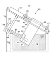
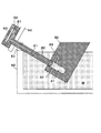
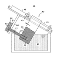
【解決手段】ホットチャンバ鋳造装置10は、溶湯を鋳型に射出する湯路が貫通して形成されたプランジャノズル20と、プランジャノズル20を進退可能に嵌挿するチャンバ室31を有する可動チャンバ30とを備える。可動チャンバ30は、プランジャノズル20側を斜め上にして、少なくともチャンバ室31全体がポッド50内の溶湯Wに浸漬した状態で設置される。油圧シリンダ42による可動チャンバ30の往復動に伴い、プランジャノズル30をチャンバ室31内で進退移動させることで、プランジャノズル20の湯路21を通して溶湯を鋳型61、62に射出する。
【選択図】図1
Description
ポッド50は、図示しない溶湯保持炉に設置される耐熱槽である。本実施形態のポッド50は、例えば700℃以上の一定温度に溶湯を加熱保持することが可能である。また、ポッド50には、公知の溶解炉から高温の溶湯が適宜に補給され、溶湯レベルが一定に保持されている。
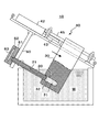
まず、チャンバ室31に溶湯Wを導入するため、図4に示すように、油圧シリンダ42のロッド43を伸長させ可動チャンバ30を押し下げる。このときチャンバ室31の容積が増し減圧されることにより、溶湯がチャンバ室31内面とプランジャノズル20の外面との間の隙間を介してチャンバ室31に導入される。
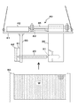
20 プランジャノズル
21 湯路
30 可動チャンバ
31 チャンバ室
32 溶湯導入孔
33 ガス抜き孔
40 駆動装置
42 油圧シリンダ
43 ロッド
44 ジョイント
45 ガイドロッド
50 ポッド(溶湯槽)
51 受け溝
60 支持部材
61 固定金型
62 可動金型
63 キャビティ
70 支持フレーム
W 溶湯
Claims (4)
- 溶融金属材料である溶湯を鋳型に射出する湯路が形成されたプランジャノズルと、
前記プランジャノズルを嵌挿するチャンバ室を有し、前記プランジャノズルをチャンバ室内で進退させるように往復動することにより、溶湯を前記チャンバ室に導入しおよび前記プランジャノズルの湯路を介して射出する可動チャンバとを備え、
前記可動チャンバが、前記プランジャノズル側を斜め上にして、少なくとも前記チャンバ室全体が前記溶湯内に浸漬した状態で設置されているホットチャンバ鋳造装置。 - 前記プランジャノズルが前記ポッドに設置される接合部分が前記溶湯のレベルよりも上にある、請求項1に記載のホットチャンバ鋳造装置。
- 前記可動チャンバが往復動する動線と前記プランジャノズルの長手方向軸とが一致している、請求項1または2に記載のホットチャンバ鋳造装置。
- 前記プランジャノズルおよび可動チャンバが前記溶湯内で分離可能であり、且つ、これらが前記ポッドから取り外し可能に設置されている、請求項1〜3の何れかに記載のホットチャンバ鋳造装置。
Priority Applications (1)
| Application Number | Priority Date | Filing Date | Title |
|---|---|---|---|
| JP2016086624A JP6727903B2 (ja) | 2016-04-23 | 2016-04-23 | ホットチャンバ鋳造装置 |
Applications Claiming Priority (1)
| Application Number | Priority Date | Filing Date | Title |
|---|---|---|---|
| JP2016086624A JP6727903B2 (ja) | 2016-04-23 | 2016-04-23 | ホットチャンバ鋳造装置 |
Publications (2)
| Publication Number | Publication Date |
|---|---|
| JP2017192980A true JP2017192980A (ja) | 2017-10-26 |
| JP6727903B2 JP6727903B2 (ja) | 2020-07-22 |
Family
ID=60155113
Family Applications (1)
| Application Number | Title | Priority Date | Filing Date |
|---|---|---|---|
| JP2016086624A Active JP6727903B2 (ja) | 2016-04-23 | 2016-04-23 | ホットチャンバ鋳造装置 |
Country Status (1)
| Country | Link |
|---|---|
| JP (1) | JP6727903B2 (ja) |
-
2016
- 2016-04-23 JP JP2016086624A patent/JP6727903B2/ja active Active
Also Published As
| Publication number | Publication date |
|---|---|
| JP6727903B2 (ja) | 2020-07-22 |
Similar Documents
| Publication | Publication Date | Title |
|---|---|---|
| ES2803600T3 (es) | Aparato y método para fundir y moldear metal en un entorno de vacío | |
| KR101565258B1 (ko) | 성형 장치, 반 응고 금속의 제조 장치, 성형 방법 및 반 응고 금속의 제조 방법 | |
| KR101061947B1 (ko) | 다이캐스팅 금형 장치 | |
| KR20130099214A (ko) | 연속 주조 용융 금속 몰드를 위한 냉각제 제어 및 와이퍼 시스템 | |
| JP2007253234A (ja) | 竪型鋳造装置及び竪型鋳造方法 | |
| JP6992085B2 (ja) | 非鉄合金のホットチャンバーダイカスト装置 | |
| JP2017192980A (ja) | ホットチャンバ鋳造装置 | |
| JP2006116598A (ja) | ダイカスト鋳造装置及びダイカスト鋳造方法 | |
| JP5210979B2 (ja) | 内燃機関用ピストンの製造方法、このピストン製造装置及びこの製造装置によって製造されたピストン | |
| JP2003305555A (ja) | ダイカスト鋳造装置及びダイカスト鋳造方法 | |
| EP3167977A1 (en) | Mold apparatus for molding metal in high vacuum environment | |
| CN219581632U (zh) | 一种压铸用模具 | |
| JP2024177576A (ja) | 加圧ロッドの動作制御方法、ダイカスト法 | |
| JP7653829B2 (ja) | ホットチャンバ鋳造装置 | |
| JP6727914B2 (ja) | ホットチャンバ鋳造装置 | |
| JP4139868B2 (ja) | 高融点金属の高圧鋳造方法およびダイカスト装置 | |
| US6752197B2 (en) | Injector particularly for vacuum die-casting apparatus | |
| JP6847722B2 (ja) | ホットチャンバ鋳造装置 | |
| JP6408328B2 (ja) | ダイカストマシンの射出装置 | |
| CN222370301U (zh) | 新型耐磨铸球覆砂模具 | |
| JP5351322B2 (ja) | 内燃機関用ピストン | |
| JP4753099B2 (ja) | ホットチャンバーダイカストマシン | |
| US20110017420A1 (en) | Apparatus and method for simultaneous usage of multiple die casting tools | |
| JP2022170594A (ja) | ホットチャンバ鋳造装置 | |
| JP2005329419A (ja) | 金属ダイキャスト成型装置および成型方法 |
Legal Events
| Date | Code | Title | Description |
|---|---|---|---|
| A621 | Written request for application examination |
Free format text: JAPANESE INTERMEDIATE CODE: A621 Effective date: 20190420 |
|
| A977 | Report on retrieval |
Free format text: JAPANESE INTERMEDIATE CODE: A971007 Effective date: 20200313 |
|
| A131 | Notification of reasons for refusal |
Free format text: JAPANESE INTERMEDIATE CODE: A131 Effective date: 20200318 |
|
| A521 | Request for written amendment filed |
Free format text: JAPANESE INTERMEDIATE CODE: A523 Effective date: 20200410 |
|
| TRDD | Decision of grant or rejection written | ||
| A01 | Written decision to grant a patent or to grant a registration (utility model) |
Free format text: JAPANESE INTERMEDIATE CODE: A01 Effective date: 20200630 |
|
| A61 | First payment of annual fees (during grant procedure) |
Free format text: JAPANESE INTERMEDIATE CODE: A61 Effective date: 20200701 |
|
| R150 | Certificate of patent or registration of utility model |
Ref document number: 6727903 Country of ref document: JP Free format text: JAPANESE INTERMEDIATE CODE: R150 |
|
| R250 | Receipt of annual fees |
Free format text: JAPANESE INTERMEDIATE CODE: R250 |
|
| R250 | Receipt of annual fees |
Free format text: JAPANESE INTERMEDIATE CODE: R250 |
|
| R250 | Receipt of annual fees |
Free format text: JAPANESE INTERMEDIATE CODE: R250 |