JP2017193322A - Hybrid-vehicular power transmission apparatus - Google Patents
Hybrid-vehicular power transmission apparatus Download PDFInfo
- Publication number
- JP2017193322A JP2017193322A JP2016195885A JP2016195885A JP2017193322A JP 2017193322 A JP2017193322 A JP 2017193322A JP 2016195885 A JP2016195885 A JP 2016195885A JP 2016195885 A JP2016195885 A JP 2016195885A JP 2017193322 A JP2017193322 A JP 2017193322A
- Authority
- JP
- Japan
- Prior art keywords
- gear
- parking
- rotating element
- parking gear
- resistance applying
- Prior art date
- Legal status (The legal status is an assumption and is not a legal conclusion. Google has not performed a legal analysis and makes no representation as to the accuracy of the status listed.)
- Withdrawn
Links
Images

Classifications
-
- B—PERFORMING OPERATIONS; TRANSPORTING
- B60—VEHICLES IN GENERAL
- B60K—ARRANGEMENT OR MOUNTING OF PROPULSION UNITS OR OF TRANSMISSIONS IN VEHICLES; ARRANGEMENT OR MOUNTING OF PLURAL DIVERSE PRIME-MOVERS IN VEHICLES; AUXILIARY DRIVES FOR VEHICLES; INSTRUMENTATION OR DASHBOARDS FOR VEHICLES; ARRANGEMENTS IN CONNECTION WITH COOLING, AIR INTAKE, GAS EXHAUST OR FUEL SUPPLY OF PROPULSION UNITS IN VEHICLES
- B60K6/00—Arrangement or mounting of plural diverse prime-movers for mutual or common propulsion, e.g. hybrid propulsion systems comprising electric motors and internal combustion engines
- B60K6/20—Arrangement or mounting of plural diverse prime-movers for mutual or common propulsion, e.g. hybrid propulsion systems comprising electric motors and internal combustion engines the prime-movers consisting of electric motors and internal combustion engines, e.g. HEVs
- B60K6/22—Arrangement or mounting of plural diverse prime-movers for mutual or common propulsion, e.g. hybrid propulsion systems comprising electric motors and internal combustion engines the prime-movers consisting of electric motors and internal combustion engines, e.g. HEVs characterised by apparatus, components or means specially adapted for HEVs
- B60K6/36—Arrangement or mounting of plural diverse prime-movers for mutual or common propulsion, e.g. hybrid propulsion systems comprising electric motors and internal combustion engines the prime-movers consisting of electric motors and internal combustion engines, e.g. HEVs characterised by apparatus, components or means specially adapted for HEVs characterised by the transmission gearings
- B60K6/365—Arrangement or mounting of plural diverse prime-movers for mutual or common propulsion, e.g. hybrid propulsion systems comprising electric motors and internal combustion engines the prime-movers consisting of electric motors and internal combustion engines, e.g. HEVs characterised by apparatus, components or means specially adapted for HEVs characterised by the transmission gearings with the gears having orbital motion
-
- B—PERFORMING OPERATIONS; TRANSPORTING
- B60—VEHICLES IN GENERAL
- B60K—ARRANGEMENT OR MOUNTING OF PROPULSION UNITS OR OF TRANSMISSIONS IN VEHICLES; ARRANGEMENT OR MOUNTING OF PLURAL DIVERSE PRIME-MOVERS IN VEHICLES; AUXILIARY DRIVES FOR VEHICLES; INSTRUMENTATION OR DASHBOARDS FOR VEHICLES; ARRANGEMENTS IN CONNECTION WITH COOLING, AIR INTAKE, GAS EXHAUST OR FUEL SUPPLY OF PROPULSION UNITS IN VEHICLES
- B60K6/00—Arrangement or mounting of plural diverse prime-movers for mutual or common propulsion, e.g. hybrid propulsion systems comprising electric motors and internal combustion engines
- B60K6/20—Arrangement or mounting of plural diverse prime-movers for mutual or common propulsion, e.g. hybrid propulsion systems comprising electric motors and internal combustion engines the prime-movers consisting of electric motors and internal combustion engines, e.g. HEVs
- B60K6/22—Arrangement or mounting of plural diverse prime-movers for mutual or common propulsion, e.g. hybrid propulsion systems comprising electric motors and internal combustion engines the prime-movers consisting of electric motors and internal combustion engines, e.g. HEVs characterised by apparatus, components or means specially adapted for HEVs
- B60K6/24—Arrangement or mounting of plural diverse prime-movers for mutual or common propulsion, e.g. hybrid propulsion systems comprising electric motors and internal combustion engines the prime-movers consisting of electric motors and internal combustion engines, e.g. HEVs characterised by apparatus, components or means specially adapted for HEVs characterised by the combustion engines
-
- B—PERFORMING OPERATIONS; TRANSPORTING
- B60—VEHICLES IN GENERAL
- B60K—ARRANGEMENT OR MOUNTING OF PROPULSION UNITS OR OF TRANSMISSIONS IN VEHICLES; ARRANGEMENT OR MOUNTING OF PLURAL DIVERSE PRIME-MOVERS IN VEHICLES; AUXILIARY DRIVES FOR VEHICLES; INSTRUMENTATION OR DASHBOARDS FOR VEHICLES; ARRANGEMENTS IN CONNECTION WITH COOLING, AIR INTAKE, GAS EXHAUST OR FUEL SUPPLY OF PROPULSION UNITS IN VEHICLES
- B60K6/00—Arrangement or mounting of plural diverse prime-movers for mutual or common propulsion, e.g. hybrid propulsion systems comprising electric motors and internal combustion engines
- B60K6/20—Arrangement or mounting of plural diverse prime-movers for mutual or common propulsion, e.g. hybrid propulsion systems comprising electric motors and internal combustion engines the prime-movers consisting of electric motors and internal combustion engines, e.g. HEVs
- B60K6/22—Arrangement or mounting of plural diverse prime-movers for mutual or common propulsion, e.g. hybrid propulsion systems comprising electric motors and internal combustion engines the prime-movers consisting of electric motors and internal combustion engines, e.g. HEVs characterised by apparatus, components or means specially adapted for HEVs
- B60K6/26—Arrangement or mounting of plural diverse prime-movers for mutual or common propulsion, e.g. hybrid propulsion systems comprising electric motors and internal combustion engines the prime-movers consisting of electric motors and internal combustion engines, e.g. HEVs characterised by apparatus, components or means specially adapted for HEVs characterised by the motors or the generators
-
- F—MECHANICAL ENGINEERING; LIGHTING; HEATING; WEAPONS; BLASTING
- F16—ENGINEERING ELEMENTS AND UNITS; GENERAL MEASURES FOR PRODUCING AND MAINTAINING EFFECTIVE FUNCTIONING OF MACHINES OR INSTALLATIONS; THERMAL INSULATION IN GENERAL
- F16H—GEARING
- F16H3/00—Toothed gearings for conveying rotary motion with variable gear ratio or for reversing rotary motion
- F16H3/44—Toothed gearings for conveying rotary motion with variable gear ratio or for reversing rotary motion using gears having orbital motion
- F16H3/72—Toothed gearings for conveying rotary motion with variable gear ratio or for reversing rotary motion using gears having orbital motion with a secondary drive, e.g. regulating motor, in order to vary speed continuously
-
- F—MECHANICAL ENGINEERING; LIGHTING; HEATING; WEAPONS; BLASTING
- F16—ENGINEERING ELEMENTS AND UNITS; GENERAL MEASURES FOR PRODUCING AND MAINTAINING EFFECTIVE FUNCTIONING OF MACHINES OR INSTALLATIONS; THERMAL INSULATION IN GENERAL
- F16H—GEARING
- F16H63/00—Control outputs from the control unit to change-speed- or reversing-gearings for conveying rotary motion or to other devices than the final output mechanism
- F16H63/02—Final output mechanisms therefor; Actuating means for the final output mechanisms
- F16H63/30—Constructional features of the final output mechanisms
- F16H63/34—Locking or disabling mechanisms
- F16H63/3416—Parking lock mechanisms or brakes in the transmission
-
- B—PERFORMING OPERATIONS; TRANSPORTING
- B60—VEHICLES IN GENERAL
- B60Y—INDEXING SCHEME RELATING TO ASPECTS CROSS-CUTTING VEHICLE TECHNOLOGY
- B60Y2200/00—Type of vehicle
- B60Y2200/90—Vehicles comprising electric prime movers
- B60Y2200/92—Hybrid vehicles
-
- Y—GENERAL TAGGING OF NEW TECHNOLOGICAL DEVELOPMENTS; GENERAL TAGGING OF CROSS-SECTIONAL TECHNOLOGIES SPANNING OVER SEVERAL SECTIONS OF THE IPC; TECHNICAL SUBJECTS COVERED BY FORMER USPC CROSS-REFERENCE ART COLLECTIONS [XRACs] AND DIGESTS
- Y02—TECHNOLOGIES OR APPLICATIONS FOR MITIGATION OR ADAPTATION AGAINST CLIMATE CHANGE
- Y02T—CLIMATE CHANGE MITIGATION TECHNOLOGIES RELATED TO TRANSPORTATION
- Y02T10/00—Road transport of goods or passengers
- Y02T10/60—Other road transportation technologies with climate change mitigation effect
- Y02T10/62—Hybrid vehicles
-
- Y—GENERAL TAGGING OF NEW TECHNOLOGICAL DEVELOPMENTS; GENERAL TAGGING OF CROSS-SECTIONAL TECHNOLOGIES SPANNING OVER SEVERAL SECTIONS OF THE IPC; TECHNICAL SUBJECTS COVERED BY FORMER USPC CROSS-REFERENCE ART COLLECTIONS [XRACs] AND DIGESTS
- Y02—TECHNOLOGIES OR APPLICATIONS FOR MITIGATION OR ADAPTATION AGAINST CLIMATE CHANGE
- Y02T—CLIMATE CHANGE MITIGATION TECHNOLOGIES RELATED TO TRANSPORTATION
- Y02T10/00—Road transport of goods or passengers
- Y02T10/60—Other road transportation technologies with climate change mitigation effect
- Y02T10/7072—Electromobility specific charging systems or methods for batteries, ultracapacitors, supercapacitors or double-layer capacitors
Landscapes
- Engineering & Computer Science (AREA)
- Mechanical Engineering (AREA)
- General Engineering & Computer Science (AREA)
- Chemical & Material Sciences (AREA)
- Combustion & Propulsion (AREA)
- Transportation (AREA)
- Gear-Shifting Mechanisms (AREA)
- Electric Propulsion And Braking For Vehicles (AREA)
- Hybrid Electric Vehicles (AREA)
Abstract
【課題】パーキング機構が働いているときに、エンジンのトルク変動に基づく、パーキング機構での歯打ち音の発生を抑制する。【解決手段】ハイブリッド車両の動力伝達装置であって、エンジンに連結された第1回転要素14と、第2回転要素11と、回転電機および駆動輪に動力伝達可能に連結された第3回転要素13Rと、を備える遊星歯車機構10と、第3回転要素と、駆動輪Wと、回転電機MG2の回転軸34と、の間に介在して動力を伝達する歯車26と、第3回転要素と一体回転するパーキングギヤ86と、爪部87aを有したパーキング噛合部材87と、を備えるパーキングロック機構80と、爪部がパーキングギヤに噛み合っている状態では、噛み合っていない状態に比べて回転抵抗を大きくするように、抵抗付与部材102をパーキングギヤ又は第3回転要素に接触させる抵抗付与装置100と、を備えている。【選択図】図5An object of the present invention is to suppress occurrence of rattling noise in a parking mechanism based on engine torque fluctuation when the parking mechanism is operating. A power transmission device for a hybrid vehicle, wherein a first rotating element connected to an engine, a second rotating element, and a third rotating element connected to a rotating electrical machine and drive wheels so as to be able to transmit power. A planetary gear mechanism 10 provided with 13R, a third rotating element, a drive wheel W, a gear 26 that transmits power through the rotating shaft 34 of the rotating electrical machine MG2, and a third rotating element. The parking lock mechanism 80 including the parking gear 86 that rotates integrally, the parking engagement member 87 having the claw portion 87a, and the rotation resistance in the state where the claw portion is engaged with the parking gear, compared to the state where the engagement is not engaged. A resistance applying device 100 that brings the resistance applying member 102 into contact with the parking gear or the third rotation element is provided. [Selection] Figure 5
Description
本発明は、ハイブリッド車両の動力伝達装置に関する。 The present invention relates to a power transmission device for a hybrid vehicle.
従来、内燃機関で生じさせた動力(トルク)を遊星歯車機構を介して回転電機と駆動輪とに伝達させることができるハイブリッド車両が知られている。このような車両においても、シフトレバー操作によりパーキングレンジが選択されたときに駆動輪をロックするパーキング機構が搭載されている。 2. Description of the Related Art Conventionally, there is known a hybrid vehicle that can transmit power (torque) generated by an internal combustion engine to a rotating electrical machine and driving wheels via a planetary gear mechanism. Such a vehicle is also equipped with a parking mechanism that locks the drive wheels when the parking range is selected by operating the shift lever.
例えば、特許文献1のハイブリッド車両は、エンジンが接続されたキャリアと、発電機が連結されたサンギヤと、所定のギヤを介して駆動用モータおよび駆動輪と接続されたリングギヤとを有した遊星歯車機構と、パーキング機構とを備えている。このパーキング機構は、パーキングレンジが選択されているときに、そのパーキングポールの爪部が、前記リングギヤに一体に形成されたパーキングギヤと係合するように構成されている。そして、この車両では、パーキング機構の爪部がパーキングギヤに噛み合っているとき、エンジンが始動された場合などのエンジンの出力トルク変動が大きいときには、そのトルク変動を打ち消すように駆動用モータを制御するとともに、制御によって該モータから出力されたトルクをパーキング機構に伝達させる。このトルクの伝達により、爪部とパーキングギヤの歯部との間の遊び(バックラッシ)に起因する歯打ち音の発生を抑制している。
For example, the hybrid vehicle disclosed in
アイドル運転状態のようにエンジンが自立運転(無負荷運転)をしているときにも、車両の静粛性の観点から上記歯打ち音を抑制することが望まれる。しかし、パーキング機構を構成するギヤ(ここでは特にリングギヤ)と、車両の駆動輪と、駆動用モータと、の間に介在して動力を伝達する歯車を有し、駆動用モータから出力されたトルクがパーキング機構に伝達される経路と、該トルクが駆動輪に伝達される経路とのそれぞれに、バックラッシが含まれる動力伝達装置においては以下の問題が生じる。駆動用モータから出力されたトルクによって、駆動用モータとパーキング機構との間のバックラッシが詰まる前に、駆動用モータと駆動輪との間のバックラッシが詰まってしまうと、該トルクは、パーキング機構には伝達されることなく、駆動輪に伝達される。その結果、この動力伝達装置においては、パーキング機構の爪部がパーキングギヤに噛み合っているとき、駆動用モータからトルクを加えても、パーキング機構のバックラッシを十分詰めることができず、エンジンのトルク変動に基づく、パーキング機構における歯打ち音の発生を抑制することが難しい。また、エンジンが自立運転をしているときに、エンジンの出力軸と同軸に配置された発電機を用いてトルクを加えると、発電機がエンジンを逆回転させる向きにトルクを与えることになるため、エンジンへの負荷が高くなり、好ましくない。 Even when the engine is operating autonomously (no-load operation) as in the idling operation state, it is desired to suppress the rattling noise from the viewpoint of the quietness of the vehicle. However, the torque output from the drive motor has a gear (in particular, a ring gear in this case) that constitutes the parking mechanism, a drive wheel of the vehicle, and a gear that transmits power through the drive motor. The following problems arise in a power transmission device including backlash in each of a path through which the torque is transmitted to the parking mechanism and a path through which the torque is transmitted to the drive wheels. If the backlash between the driving motor and the driving wheel is clogged before the backlash between the driving motor and the parking mechanism is clogged by the torque output from the driving motor, the torque is transferred to the parking mechanism. Is transmitted to the drive wheels without being transmitted. As a result, in this power transmission device, when the pawl portion of the parking mechanism is engaged with the parking gear, even if torque is applied from the drive motor, the backlash of the parking mechanism cannot be sufficiently reduced, and the engine torque fluctuations Therefore, it is difficult to suppress the occurrence of rattling noise in the parking mechanism. In addition, when the engine is operating independently, if torque is applied using a generator arranged coaxially with the output shaft of the engine, torque will be applied in the direction in which the generator rotates the engine in the reverse direction. The load on the engine increases, which is not preferable.
そこで、本発明の目的は、駆動用モータおよびエンジンから出力されるトルクを伝達する動力伝達装置を備えたハイブリッド車両において、エンジンのトルク変動が小さいときにも、パーキングレンジが選択されてパーキング機構が働いているとき、エンジンのトルク変動に基づく、パーキング機構における歯打ち音の発生を抑制することにある。 SUMMARY OF THE INVENTION Accordingly, an object of the present invention is to provide a hybrid vehicle including a drive motor and a power transmission device that transmits torque output from an engine, even when the engine torque fluctuation is small, the parking range is selected and the parking mechanism is It is to suppress the occurrence of rattling noise in the parking mechanism based on engine torque fluctuation when working.
本発明の一態様によれば、
ハイブリッド車両の動力伝達装置であって、
エンジンに連結された第1回転要素と、第2回転要素と、回転電機および駆動輪に動力伝達可能に連結された第3回転要素と、を備える遊星歯車機構と、
前記第3回転要素と、前記駆動輪と、前記回転電機の回転軸と、の間に介在して動力を伝達する歯車と、
前記第3回転要素と一体回転するように設けられたパーキングギヤと、該パーキングギヤに噛み合うことができる爪部を有し、パーキングレンジの選択状態に応じて前記爪部が前記パーキングギヤに対して噛み合っている状態と噛み合っていない状態とを切り替えるように動作するパーキング噛合部材と、を備えるパーキングロック機構と、
前記パーキングギヤまたは前記第3回転要素に対して接触することにより、前記パーキングギヤまたは前記第3回転要素へ回転抵抗を与えることができる抵抗付与部材を有し、前記パーキング噛合部材の前記爪部が前記パーキングギヤに噛み合っている状態においては、噛み合っていない状態に比べて前記回転抵抗を大きくするように、前記パーキングギヤまたは前記第3回転要素に前記抵抗付与部材を接触させる抵抗付与装置と、
を備えたハイブリッド車両の動力伝達装置
が提供される。
According to one aspect of the invention,
A power transmission device for a hybrid vehicle,
A planetary gear mechanism comprising: a first rotating element coupled to the engine; a second rotating element; and a third rotating element coupled to the rotating electrical machine and the driving wheel so as to be capable of transmitting power.
A gear that is interposed between the third rotating element, the driving wheel, and a rotating shaft of the rotating electrical machine to transmit power;
A parking gear provided to rotate integrally with the third rotating element; and a claw portion capable of meshing with the parking gear, wherein the claw portion is connected to the parking gear according to a selected state of a parking range. A parking lock member that operates to switch between a meshed state and a non-engaged state; and a parking lock mechanism comprising:
A resistance applying member capable of giving a rotational resistance to the parking gear or the third rotating element by contacting the parking gear or the third rotating element; and the pawl portion of the parking meshing member A resistance applying device for bringing the resistance applying member into contact with the parking gear or the third rotating element so as to increase the rotational resistance in a state in which the parking gear is engaged, compared to a state in which the parking gear is not engaged;
A power transmission device for a hybrid vehicle is provided.
好ましくは、前記抵抗付与部材は、前記パーキング噛合部材の動作に連動し、前記爪部が前記パーキングギヤと噛み合っていない状態においては前記パーキングギヤまたは前記第3回転要素から離れ、前記爪部が前記パーキングギヤに噛み合っている状態においては前記パーキングギヤまたは前記第3回転要素に接触するとよい。 Preferably, the resistance applying member is interlocked with the operation of the parking meshing member, and is separated from the parking gear or the third rotation element in a state where the pawl is not meshed with the parking gear, and the pawl is In the state of being engaged with the parking gear, the parking gear or the third rotating element may be contacted.
なお、前記抵抗付与部材は、前記パーキング噛合部材に機械的に連結されていてもよい。あるいは、前記抵抗付与装置は、前記パーキングギヤまたは前記第3回転要素との接触状態を変化させるように前記抵抗付与部材を駆動する駆動部と、該駆動部の作動を制御する制御部とを更に有し、該制御部は、前記爪部が前記パーキングギヤに噛み合っている状態において、前記爪部が前記パーキングギヤに噛み合っていない状態に比べて、前記抵抗付与部材が前記パーキングギヤまたは前記第3回転要素に与える前記回転抵抗を大きくするように前記駆動部を作動させるとよい。この場合、前記制御部は、前記エンジンが自立運転している場合に、前記抵抗付与部材が前記パーキングギヤまたは前記第3回転要素に与える前記回転抵抗を大きくするように前記駆動部を作動させるとよい。 The resistance applying member may be mechanically connected to the parking engagement member. Alternatively, the resistance applying device further includes a drive unit that drives the resistance applying member so as to change a contact state with the parking gear or the third rotating element, and a control unit that controls the operation of the drive unit. And the control unit is configured such that the resistance-applying member in the state in which the claw part is engaged with the parking gear is greater than that in the state in which the claw part is not engaged with the parking gear. The drive unit may be operated so as to increase the rotational resistance applied to the rotating element. In this case, when the control unit operates the drive unit so as to increase the rotation resistance applied to the parking gear or the third rotation element by the resistance applying member when the engine is operating independently. Good.
好ましくは、前記抵抗付与部材は、前記パーキング噛合部材の動作に連動し、前記爪部が前記パーキングギヤに噛み合っている状態において、該爪部が噛み合う歯面の歯溝とは異なる歯溝の歯面に接触するとよい。 Preferably, the resistance applying member is interlocked with the operation of the parking meshing member, and in a state where the pawl portion is meshed with the parking gear, a tooth of a tooth gap different from a tooth surface of the tooth surface with which the pawl portion meshes. Contact the surface.
好ましくは、前記第3回転要素は、前記パーキングギヤと一体回転するように設けられた回転抑制部材を更に有し、前記抵抗付与部材は、前記回転抑制部材に接触することにより、前記第3回転要素へ前記回転抵抗を与えることができ、前記抵抗付与装置は、前記爪部が前記パーキングギヤに噛み合っている状態において、前記爪部が前記パーキングギヤに噛み合っていない状態に比べて、前記第3回転要素へ与える前記回転抵抗を大きくするように前記抵抗付与部材を作動させるとよい。 Preferably, the third rotation element further includes a rotation suppressing member provided to rotate integrally with the parking gear, and the resistance applying member contacts the rotation suppressing member to thereby perform the third rotation. The rotational resistance can be applied to an element, and the resistance applying device is configured so that the claw portion is engaged with the parking gear in a state where the claw portion is not engaged with the parking gear. The resistance applying member may be operated so as to increase the rotational resistance applied to the rotating element.
本発明の上記一態様によれば、パーキングレンジが選択されて爪部がパーキングギヤに噛み合っている状態においては、爪部がパーキングギヤに噛み合っていない状態に比べて回転抵抗を大きくするように、抵抗付与部材が、抵抗付与装置によって、パーキングギヤまたは第3回転要素に接触させられる。この接触による摩擦により、パーキングギヤまたは第3回転要素の動きが抑制され、その結果、爪部とパーキングギヤとの相対移動が抑制される。したがって、パーキングレンジが選択されてパーキング機構が働いているときに、エンジンのトルク変動に基づく、パーキング機構における歯打ち音の発生を抑制することができる、という優れた効果が発揮される。 According to the one aspect of the present invention, in the state where the parking range is selected and the claw portion is engaged with the parking gear, the rotation resistance is increased as compared with the state where the claw portion is not engaged with the parking gear. The resistance applying member is brought into contact with the parking gear or the third rotating element by the resistance applying device. The friction due to the contact suppresses the movement of the parking gear or the third rotating element, and as a result, the relative movement between the claw portion and the parking gear is suppressed. Therefore, when the parking range is selected and the parking mechanism is working, an excellent effect is exhibited that it is possible to suppress the occurrence of rattling noise in the parking mechanism based on engine torque fluctuation.
以下、本発明の実施形態について図面を参照しつつ詳細に説明する。
[第1実施形態]
まず、本発明に係る第1実施形態について説明する。第1実施形態は、ハイブリッド車両の動力伝達装置に関し、以下に説明するようにハイブリッド車両に適用されている。
Hereinafter, embodiments of the present invention will be described in detail with reference to the drawings.
[First Embodiment]
First, a first embodiment according to the present invention will be described. The first embodiment relates to a power transmission device for a hybrid vehicle, and is applied to a hybrid vehicle as described below.
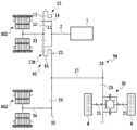
図1は、第1実施形態に係る車両における動力伝達系のスケルトン図である。第1実施形態に係る車両は、図1に示すように、動力源つまり原動機として、エンジン1、第1回転電機MG1および第2回転電機MG2を有するハイブリッド(HV)車両である。
FIG. 1 is a skeleton diagram of a power transmission system in a vehicle according to the first embodiment. As shown in FIG. 1, the vehicle according to the first embodiment is a hybrid (HV) vehicle having an
図1から図3に示すように、車両は、エンジン1、遊星歯車機構10、差動装置30、第1回転電機MG1、第2回転電機MG2、HV_ECU50、MG_ECU60、エンジン_ECU70、および本実施形態でのパーキング機構であるパーキングロック機構80を含んで構成されている。特に、エンジン1および2つの回転電機MG1、MG2と駆動輪Wとの間には、動力伝達装置TMが組み込まれ、この動力伝達装置TMは、遊星歯車機構10、パーキングロック機構80とを含むことに加えて、歯打ち音の発生を抑制するために後述する抵抗付与装置を含んでいる。
As shown in FIGS. 1 to 3, the vehicle includes an
まず、抵抗付与装置以外の構成について説明する。内燃機関であるエンジン1は、燃料の燃焼エネルギーを出力軸の回転運動に変換して出力する。エンジン1の出力軸は、動力伝達装置TMの入力軸2と接続されている。入力軸2は、エンジン1の出力軸と同軸かつ該出力軸の延長線上に配置されている。入力軸2は、遊星歯車機構10のキャリア14に固定されている。
First, configurations other than the resistance applying device will be described. The
遊星歯車機構10は、エンジン1と接続されており、エンジン1の回転(動力)を第1回転電機MG1や差動装置30などへ伝達可能である。遊星歯車機構10は、シングルピニオン式であり、サンギヤ11(第2回転要素)、プラネタリギヤ12、リングギヤ13(第3回転要素)、およびキャリア14(第1回転要素)を有している。
The
リングギヤ13は、サンギヤ11と同軸であって、かつ、サンギヤ11の径方向外側に配置されている。プラネタリギヤ12は、サンギヤ11とリングギヤ13との間に配置されており、サンギヤ11およびリングギヤ13とそれぞれ噛み合っている。また、プラネタリギヤ12は、キャリア14によって回転自在に支持されている。キャリア14は、入力軸2に固定されており、入力軸2と一体回転する。したがって、プラネタリギヤ12は、入力軸2と共に入力軸2の中心軸線周りに回転(公転)可能であり、かつキャリア14によって支持されてプラネタリギヤ12の軸線を中心として回転(自転)可能である。
The
サンギヤ11には第1回転電機MG1の回転軸33が固定されており、回転軸33はサンギヤ11と一体回転する。第1回転電機MG1の回転軸33は、入力軸2と同軸に配置されている。リングギヤ13には、カウンタドライブギヤ25が設けられており、カウンタドライブギヤ25とリングギヤ13とは一体回転するようになっている。そのため、リングギヤ13は、第1回転電機MG1あるいはエンジン1から入力される回転(動力)を、カウンタドライブギヤ25を介して駆動輪Wに出力することができる。
A rotating
カウンタドライブギヤ25は、カウンタドリブンギヤ26と噛み合っている。カウンタドリブンギヤ26は、カウンタシャフト27を介してドライブピニオンギヤ28と接続されている。カウンタドリブンギヤ26とドライブピニオンギヤ28とは、一体回転するようになっている。また、カウンタドリブンギヤ26には、リダクションギヤ35が噛み合っている。リダクションギヤ35には、第2回転電機MG2の回転軸34が固定されている。つまり、第2回転電機MG2の出力する回転(動力)は、リダクションギヤ35を介してカウンタドリブンギヤ26に伝達される。なお、リダクションギヤ35は、カウンタドリブンギヤ26よりも小径であり、そのため第2回転電機MG2の出力する回転(動力)を減速してカウンタドリブンギヤ26に伝達する。
The
ドライブピニオンギヤ28は、差動装置30のデフリングギヤ29と噛み合っている。そして、差動装置30は、左右の駆動軸31を介して駆動輪Wと接続されている。
The
このように、リングギヤ13は、カウンタドライブギヤ25、カウンタドリブンギヤ26、ドライブピニオンギヤ28、差動装置30および駆動軸31を介して駆動輪Wと接続されている。また、第2回転電機MG2(の回転軸34)は、リングギヤ13と駆動輪Wとの間の動力伝達経路に対し、カウンタドリブンギヤ26を介して接続されており、リングギヤ13および駆動輪Wのそれぞれに動力を伝達可能である。即ち、第2回転電機MG2が、本発明の回転電機に対応する。
As described above, the
第1回転電機MG1および第2回転電機MG2は、それぞれモータ(電動機)としての機能と、発電機としての機能とを備えている。第1回転電機MG1および第2回転電機MG2は、不図示のインバータを介してバッテリ(不図示)と接続されている。第1回転電機MG1および第2回転電機MG2は、バッテリから供給される電力を機械的な動力に変換して出力することができると共に、回転軸に入力される動力によって駆動され、その機械的な動力を電力に変換(発電)することができる。回転電機MG1、MG2によって発電された電力は、インバータを介してバッテリに蓄電可能である。第1回転電機MG1および第2回転電機MG2には、例えば、交流同期型のものを用いることができる。 The first rotating electrical machine MG1 and the second rotating electrical machine MG2 each have a function as a motor (electric motor) and a function as a generator. The first rotating electrical machine MG1 and the second rotating electrical machine MG2 are connected to a battery (not shown) via an inverter (not shown). The first rotating electrical machine MG1 and the second rotating electrical machine MG2 can convert the electric power supplied from the battery into mechanical power and output it, and are driven by the power input to the rotating shaft. Power can be converted into electric power (power generation). The electric power generated by the rotating electrical machines MG1 and MG2 can be stored in the battery via the inverter. As the first rotating electrical machine MG1 and the second rotating electrical machine MG2, for example, an AC synchronous type can be used.
第1実施形態の車両では、エンジン1と同軸に、遊星歯車機構10、カウンタドライブギヤ25、および第1回転電機MG1が配置されている。また、第1実施形態の車両の動力伝達装置TMは、エンジン1の出力軸が接続された入力軸2と、本発明の回転電機としての第2回転電機MG2の回転軸34とが並列に配された構成とされている。
In the vehicle of the first embodiment, the
ここで、パーキングロック機構80について、図2および図1を参照して説明する。図2は、パーキングロック機構80の構成を説明する図であり、パーキングロック機構80は、駆動輪Wの回転を機械的に阻止する構成を備えている。図2において、パーキングロック機構80は、パーキングロック駆動モータ82を備え、後述するHV_ECUからの制御信号に基づき車両の移動を防止するために作動する。
Here, the
パーキングロック機構80は、パーキングロック駆動モータ82により回転駆動されるシャフト83、このシャフト83に固定され、シャフト83と一体回転することでパーキングロック位置決め部材として機能するディテントプレート84、およびディテントプレート84の回転に伴って作動するロッド85を備えている。このパーキングロック機構80では、パーキングロック駆動モータ82によるシャフト83の回転駆動に伴ってディテントプレート84が回転することにより、Pレンジが選択されたことに対応するパーキングロックポジション(噛合位置)と、それ以外の各シフトポジションに対応する非パーキングロックポジション(非噛合位置)とが切り替えられる。なお、シフトポジションには、Pレンジ(パーキングレンジ)、Nレンジ、Dレンジ、Rレンジを含む複数のシフトポジションがあり、運転者の操作により、シフトレバーはそれら複数のシフトポジションのうちのいずれか1つに対応付けられる。また、パーキングロック機構80は、ディテントプレート84の回転を制限してシフトポジションを固定するディテントスプリング88、ころ89、パーキングギヤ86、およびパーキングギヤ86の回転を阻止(ロック)するためのパーキングロックポール87を備えている。なお、パーキングロックポール87は、本発明のパーキング噛合部材に相当する。
The
図1に示すように、パーキングギヤ86は、遊星歯車機構10の出力ギヤであるリングギヤ13に同軸かつ一体的に設けられ、リングギヤ13と、該リングギヤ13と一体回転するカウンタドライブギヤ25と、の両方と一体回転するように設けられており、駆動輪Wとも連動して回転する。なお、リングギヤ13と、これと共に一体回転するパーキングギヤ86およびカウンタドライブギヤ25とを合わせた部材を、ここでは、リングギヤ部材13Rと称する。
As shown in FIG. 1, the
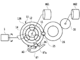
ところで、図2は、パーキングロック機構80が非パーキングロックポジション(非噛合位置)にあるときの状態を示している。この状態では、パーキングロックポール87の爪部87aはパーキングギヤ86に(詳しくはパーキングギヤ86のいずれの歯面にも)噛み合っておらずロックしていないので、駆動輪Wの回転がパーキングロック機構80によって妨げられることはない。なお、パーキングロックポール87は、パーキングギヤ86の回転軸線を中心とした径方向の外側に位置するように設けられている。また、パーキングロックポール87を回動可能に支持する支持部87bには、パーキングギヤ86から離れる方向の弾性力を有したねじりばね87cが取付けられている。そして、パーキングロックポール87は、このねじりばね87cの有する弾性力に逆らって上記径方向の内側に向けて動くことで、爪部87aがパーキングギヤ86に設けられた複数の歯の歯溝のうちの何れかに向けて移動して該歯溝の歯面に係合し得るように配置されている。つまり、Pレンジが選択されていないとき、パーキングロックポール87は、その支持部87bに取付けられたねじりばね87cの有する弾性力によって、非パーキングロックポジション(非噛合位置)の位置に維持されるようになっている。
Incidentally, FIG. 2 shows a state when the
この状態から、(Pレンジが選択されたときに作動される)パーキングロック駆動モータ82によってシャフト83を矢印A1の方向に回転させると、ディテントプレート84が同じ方向に回転し、その回転に伴ってロッド85が矢印A2の方向に押される。その結果、パーキングロックポール87が、ロッド85の(矢印A2の方向の)先端に設けられたテーパー部材85aによって矢印A3の方向にねじりばね87cの有する弾性力に逆らって押し上げられる。また、ディテントプレート84の回転に伴って、それまで非パーキングロックポジションにあったディテントスプリング88のころ89は、ディテントプレート84の山部84aを乗り越えてパーキングロックポジション(噛合位置)へ移ろうとする。そして、ころ89がパーキングロックポジションに移るところまで、ディテントプレート84が回転したときに、パーキングロックポール87の爪部87aは、パーキングギヤ86と噛み合う位置まで押し上げられる。これにより、パーキングギヤ86の回転が機械的に阻止されるようになる。このように、パーキングロックポジションでは、リングギヤ13に一体回転するように設けられたパーキングギヤ86に対し、所定の非回転部材(パーキング噛合部材)としてのパーキングロックポール87の爪部87aを噛み込ませる。これにより、パーキングロックポジションでは、エンジン1の動力を駆動輪Wに伝達する動力伝達系において、リングギヤ13から下流の駆動輪Wとの間における回転の伝達を阻止し、車両の移動を制限する。
From this state, when the
ここで、再び、第1実施形態の車両の説明にもどる。 Here, returning to the description of the vehicle of the first embodiment.
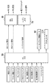
図3は、第1実施形態の車両における制御系の構成を示すブロック図である。図3に示すように、第1実施形態の車両は、HV_ECU50、MG_ECU60、およびエンジン_ECU70を有している。各ECU50、60、70は、コンピュータを有する電子制御ユニットとして構成されている。HV_ECU50は、車両全体を統合制御する機能を有している。MG_ECU60およびエンジン_ECU70は、それぞれ、HV_ECU50と電気的に接続されている。なお、HV_ECU50、MG_ECU60、およびエンジン_ECU70は、実質的に、全体として1つの電子制御ユニット(制御装置)として構成されているが、これらは、当初より一体的なユニット装置として構成されてもよい。
FIG. 3 is a block diagram illustrating a configuration of a control system in the vehicle according to the first embodiment. As shown in FIG. 3, the vehicle according to the first embodiment includes an
MG_ECU60は、第1回転電機MG1および第2回転電機MG2を制御することができる。MG_ECU60は、例えば、第1回転電機MG1に供給する電流値を調節して、その出力トルクを制御すること、および第2回転電機MG2に供給する電流値を調節して、その出力トルクを制御することができる。また、MG_ECU60は、例えば、第1回転電機MG1の発電時には、その発電量を制御することができる。
The
エンジン_ECU70は、エンジン1を制御することができる。エンジン_ECU70は、例えば、エンジン1の電子スロットル弁の開度を制御すること、点火信号を出力してエンジン1の点火制御を行うこと、エンジン1に対する燃料の噴射制御等を行うことができる。エンジン_ECU70は、このような制御を行うことによりエンジン1の出力トルクを制御することができる。
The
また、HV_ECU50には、車速センサ、アクセル開度センサ、ブレーキスイッチ、シフトポジションセンサ、MG1回転数センサ、MG2回転数センサ、出力軸回転数センサ、バッテリセンサ等が接続されている。これらのセンサにより、HV_ECU50は、車速、アクセル開度、ブレーキペダルの踏み込み状態、選択されたレンジ(シフトポジション)、第1回転電機MG1の回転数、第2回転電機MG2の回転数、動力伝達装置TMの出力軸(例えば、カウンタシャフト27)の回転数、SOC(State Of Charge)等の情報を取得することができる。
The
HV_ECU50は、取得した情報に基づいて、車両に対する要求駆動力や要求パワー、要求トルク等の要求値を算出する。HV_ECU50は、算出した要求値に基づいて、第1回転電機MG1の出力トルク(MG1トルク)、第2回転電機MG2の出力トルク(MG2トルク)、およびエンジン1の出力トルク(エンジントルク)を決定し、それらによる総合的な出力トルク(アウトプットトルク)を決定する。その決定の下、HV_ECU50は、MG1トルク指令(値)およびMG2トルク指令(値)をMG_ECU60に対して出力する。また、HV_ECU50は、エンジントルク指令(値)をエンジン_ECU70に対して出力する。
The
また、HV_ECU50は、シフトポジションセンサの出力に基づいてPレンジが選択されたことを検出したときに、パーキングロック機構80をパーキングロックポジション(噛合位置)とするように、パーキングロック駆動モータ82に対して、モータを作動させるべく制御信号を出力する。なお、シフトレバーに機械的に連結されたリンク機構を用いて、運転者のシフトレバー操作によりPレンジが選択されたときに、そのリンク機構でパーキングロックポール87を直接作動させて、その爪部87aをパーキングギヤ86に対して噛み込ませるようにしてもよい。
Further, when the
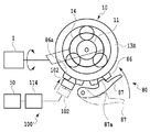
また、後述のとおり、抵抗付与部材を電子制御によって動かすように抵抗付与装置が構成される場合、HV_ECU50(詳しくはHV_ECU50の制御部)は、該抵抗付与部材をパーキングギヤ86に接触させる/パーキングギヤ86から離して非接触とさせるように、それを駆動するアクチュエータ(駆動部)114に対して作動信号を出力する。
As will be described later, when the resistance applying device is configured to move the resistance applying member by electronic control, the HV_ECU 50 (specifically, the control unit of the HV_ECU 50) causes the resistance applying member to contact the
ところで、上記のパーキングロック機構80では、それがパーキングロックポジションにあるときのパーキングロックポール87の爪部87aには、パーキングギヤ86に対して単に押し付ける向きの力が作用しているに過ぎない。そして、その爪部87aと、爪部87aが噛み合っているパーキングギヤ86の歯面との間には遊び、つまり、所謂バックラッシがある。それ故、車両が停車していてPレンジが選択されているため爪部87aがパーキングギヤ86に噛み合っている状態で、エンジン1が、アイドル運転状態のように自立運転の状態になると、エンジン1のトルク変動によりリングギヤ13つまりパーキングギヤ86を回転させる向きの力がリングギヤ部材13Rに作用する。なお、自立運転とは、エンジン1の無負荷運転のことである。この作用により、パーキングロック機構80では、爪部87aと、この爪部87aが噛み合っているパーキングギヤ86の歯面との間でそれらの衝突音(歯打ち音)が生じる。図4に、爪部87aとパーキングギヤ86との間で衝突音が生じているところを模式的に示す。この衝突音は、リングギヤ部材13Rが、矢印A5で示すように回転方向が切り替わるように動くことで継続して生じ続ける。
By the way, in the
さらに、リングギヤ部材13Rがそのように動くことで、リングギヤ部材13Rのカウンタドライブギヤ25と、カウンタドリブンギヤ26との噛み合い箇所でも同様に、衝突音(歯打ち音)が生じる。例えば、第2回転電機MG2によってガタ詰めトルクを発生させた場合、カウンタドリブンギヤ26から駆動輪Wの方向へガタ詰めトルクが伝達されて駆動輪Wまでの間に配置されたギヤについてのガタ詰めがされると、それ以上カウンタドリブンギヤ26は動かなくなってしまう。そのため、そのガタ詰めの後には、カウンタドリブンギヤ26は固定された状態(第2回転電機MG2の発生させたガタ詰めトルクが駆動輪Wに吸収された状態)となり、遊星歯車機構10の第3回転要素でもあるリングギヤ部材13Rへはガタ詰めトルクが伝達されずリングギヤ部材13Rとの間のガタを詰めることができなくなってしまう。これにより、第2回転電機MG2によってガタ詰めトルクを発生させた場合にも、リングギヤ部材13Rのカウンタドライブギヤ25と、カウンタドリブンギヤ26との噛み合い箇所で、衝突音が生じることとなる。
Further, when the
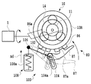
そこで、これらの衝突音(歯打ち音)の発生を抑制するべく、第1実施形態では、抵抗付与装置100を備えている。この抵抗付与装置100について、図5を参照して説明する。図5は、図4と同じように、動力伝達装置TMの一部を遊星歯車機構10の回転軸線に直交する面の側から見た模式図であり、特に、衝突音の発生に関係する車両の構成要素であるエンジン1、遊星歯車機構10、パーキングロック機構80、および抵抗付与装置100の構成を示した図である。図5では、非パーキングロックポジション(非噛合位置)にあるパーキングロックポール87が破線で示されている。
Therefore, in order to suppress the occurrence of these collision sounds (tooth rattling sounds), the
抵抗付与装置100は、抵抗付与部材としての接触部材102、パーキングロックポール87に一体的に設けられてスライド孔104aを備える第1部材104、接触部材102を保持すると共に第1部材104と連動する第2部材106、および、第2部材106に連結された緩衝装置108を備える。第2部材106は、その一端がスライド孔104aに沿ってスライド可能なように第1部材104に取り付けられている。図5に破線で示すように、パーキングロックポール87が非パーキングロックポジションにあるとき、接触部材102をリング部材13Rから離すように、第2部材106はスライド孔104aの所定の位置にある。
The
Pレンジが選択されて、パーキングロックポール87がパーキングロックポジション(噛合位置)に動かされるとき、第2部材106はスライド孔104aに沿ってリング部材13Rの方に向かうように移動する。これにより、第2部材106の保持する接触部材102が、リングギヤ部材13Rのうちのパーキングギヤ86に近づき、その歯86aに接触するようになる。このように接触部材102がパーキングギヤ86に対して接触することで、接触部材102とパーキングギヤ86との間に摩擦を生じさせる。これにより、(リングギヤ13を含む)リングギヤ部材13Rの動きが抑制され、その結果、パーキングロックポール87の爪部87aとパーキングギヤ86との相対移動が抑制されるようになる。なお、このときの接触部材102のパーキングギヤ86に対する押付力は、緩衝装置108の圧縮ばね108aによってある程度以下に抑えられるようになっている。そのため、接触部材102がパーキングギヤ86に接するときにパーキングギヤ86が徒に負荷を受けるのを防ぐことができる。なお、接触部材102はパーキングギヤ86に傷を付けないような材料(好ましくは、リングギヤ部材13Rの硬さよりも低い硬さを有する材料)から作られるとよい。一般に、Pレンジが選択されるときは、車速がゼロのとき、つまり停車中であるので、接触部材102をそのような材料で作ることが可能である。
When the P range is selected and the
以上述べたように、第1実施形態では、Pレンジが選択されて、パーキングロックポール87の爪部87aがパーキングギヤ86に噛み合っているとき、抵抗付与装置100の接触部材102がパーキングギヤ86に対して接触することで、(リングギヤ13を含む)リングギヤ部材13Rの動きが抑制される。これにより、爪部87aとパーキングギヤ86との間での衝突音の発生を抑制することができ、さらに、リングギヤ部材13Rのカウンタドライブギヤ25とカウンタドリブンギヤ26との噛み合い箇所での衝突音の発生も同様に抑制できる。
As described above, in the first embodiment, when the P range is selected and the
[第2実施形態]
図6を参照して、本発明の第2実施形態について説明する。第2実施形態は、抵抗付与装置の構成の点で、第1実施形態と相違する。そこで、以下では、第1実施形態の説明を参照することにより当業者であれば明らかである点については説明を省略または簡潔に行い、第2実施形態の特徴的な構成および機能について説明する。以下の説明では、第1実施形態の説明において既に説明した構成要素と同様の機能を有する構成要素には、同様の符号を付して重複説明を省略する。ただし、第1実施形態において説明されたような修正および変更は、矛盾しない限り、第2実施形態にも同様に適用される。
[Second Embodiment]
A second embodiment of the present invention will be described with reference to FIG. The second embodiment is different from the first embodiment in the configuration of the resistance applying device. Therefore, in the following, the description will be omitted or briefly described for those skilled in the art by referring to the description of the first embodiment, and the characteristic configuration and function of the second embodiment will be described. In the following description, components having the same functions as those already described in the description of the first embodiment are denoted by the same reference numerals, and redundant description is omitted. However, modifications and changes as described in the first embodiment are similarly applied to the second embodiment as long as there is no contradiction.
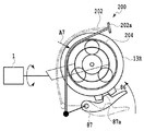
第2実施形態の抵抗付与装置200では、抵抗付与部材として板ばね状摩擦部材202を用いている。板ばね状摩擦部材202は、その一端は固定要素(例えば、ケース部材)に固定され、また、その他端がパーキングロックポール87に固定されることで、パーキングロックポール87の動きに連動するように構成されている。この板ばね状摩擦部材202は、リングギヤ部材13Rの回転軸線を中心とした径方向において外側に離れる方向の弾性力を有している。なお、リングギヤ部材13Rには、板ばね状摩擦部材202が接することができる円環状部204が設けられている。この円環状部204は、リングギヤ部材の回転軸線方向に延出するように、リングギヤ部材13Rと一体に設けられている。
In the
図6に破線で示すように、パーキングロックポール87が非パーキングロックポジション(非噛合位置)にあるとき(つまりPレンジが選択されていないとき)、板ばね状摩擦部材202は、その弾性力によりリングギヤ部材13Rから離れて接触せず、動力伝達系の各回転要素の動きを妨げないようになっている。Pレンジが選択されると、パーキングロックポール87がパーキングロックポジション(噛合位置)に動き、これにより板ばね状摩擦部材202がその弾性力と反対の方向に引かれて、図6の矢印A7で示すようにリングギヤ部材13Rの円環状部204に当接する。そして、その当接による摩擦力によって、板ばね状摩擦部材202がリングギヤ部材13Rの動きを抑制するようになる。つまり、板ばね状摩擦部材202は、リングギヤ13の動きもパーキングギヤ86の動きも実質的に抑制するようになる。このように、板ばね状摩擦部材202によってリングギヤ部材13Rの動きが抑制されるので、第2実施形態においても、パーキングロックポール87の爪部87aとパーキングギヤ86との間での衝突音の発生を抑制することができ、さらに、リングギヤ部材13Rのカウンタドライブギヤ25とカウンタドリブンギヤ26との噛み合い箇所での衝突音の発生も抑制できる。
As shown by a broken line in FIG. 6, when the
[第3実施形態]
図7を参照して、本発明の第3実施形態について説明する。第3実施形態は、抵抗付与装置の構成の点で、第1および第2実施形態と相違する。そこで、以下では、上記各実施形態の説明を参照することにより当業者であれば明らかである点については説明を省略または簡潔に行い、第3実施形態の特徴的な構成および機能について説明する。以下の説明では、上記各実施形態の説明において既に説明した構成要素と同様の機能を有する構成要素には、同様の符号を付して重複説明を省略する。ただし、上記各実施形態において説明されたような修正および変更は、矛盾しない限り、第3実施形態にも同様に適用される。
[Third Embodiment]
A third embodiment of the present invention will be described with reference to FIG. The third embodiment is different from the first and second embodiments in the configuration of the resistance applying device. Therefore, in the following description, the points that are apparent to those skilled in the art by referring to the description of each of the above embodiments will be omitted or briefly described, and the characteristic configuration and function of the third embodiment will be described. In the following description, components having the same functions as those already described in the description of the above embodiments will be given the same reference numerals, and redundant description will be omitted. However, the modifications and changes described in the above embodiments are similarly applied to the third embodiment as long as there is no contradiction.
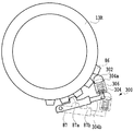
第3実施形態の抵抗付与装置300は、抵抗付与部材としてボール状部材302を備えている。抵抗付与装置300は、ボール状部材302に加えて、さらに、ボール状部材302の略半分が外部に突き出るようにボール状部材302を保持するハウジング部材304と、ボール状部材302をハウジング部材304の外部に向けて突き出すように付勢するばね部材306とを備えている。なお、ばね部材306には圧縮ばねが用いられている。ボール状部材302は、リングギヤ部材13Rのパーキングギヤ86の歯溝の幅(つまり、互いに隣り合う2つの歯の間の間隔)よりも大きな直径を有している。ボール状部材302は、リングギヤ部材13Rよりも柔らかい材料(好ましくは、リングギヤ部材13Rの硬さよりも低い硬さを有する材料)から作られるとよい。なお、図7では明らかにしていないが、ハウジング部材304からボール状部材302が脱落することが無いように、ハウジング部材304の開口部304aは縮径されてボール状部材302の外径よりも小さい径を有するように加工されている。ハウジング部材304は、パーキングロックポール87の自由端87b側のそこから延出した部材304bに設けられている。
A
図7に破線で示すように、パーキングロックポール87が非パーキングロックポジション(非噛合位置)にあるとき(つまりPレンジが選択されていないとき)、ボール状部材302は、リング状部材13Rから離れて、動力伝達系の各回転要素の動きを妨げないようになっている。Pレンジが選択されると、図7に示すように、パーキングロックポール87がパーキングロックポジション(噛合位置)に動き、これによりボール状部材302は、パーキングロックポール87の爪部87aが噛み合うパーキングギヤ86の歯面の歯溝とは異なる歯溝の歯面に噛み合うようになる。この噛み合い摩擦により、リングギヤ部材13Rの動きが抑制される。よって、第3実施形態においても、爪部87aとパーキングギヤ86との間での衝突音の発生を抑制することができ、さらに、リングギヤ部材13Rのカウンタドライブギヤ25とカウンタドリブンギヤ26との噛み合い箇所での衝突音の発生も抑制できる。
As indicated by a broken line in FIG. 7, when the
[第4実施形態]
図8および図9を参照して、本発明の第4実施形態について説明する。第4実施形態は、第1実施形態の変形バージョンに相当する。第1実施形態では、抵抗付与部材としての接触部材102をパーキングロックポール87に機械的に連結してパーキングロックポール87に連動させた。これに対し、第4実施形態では、抵抗付与部材としての接触部材102を電子制御によって動かすようにしている。以下では、第4実施形態の、第1実施形態との相違点についてのみ説明する。図8に示すとおり、接触部材102は、ここでは電動モータによるアクチュエータ(前記抵抗付与部材を駆動する駆動部)114に接続され、そのアクチュエータ114がHV_ECU50の制御部(前記駆動部の作動を制御する制御部)からの制御信号に基づき作動される。即ち、第4実施形態では、接触部材102、アクチュエータ114、HV_ECU50の制御部によって抵抗付与装置100’が構成されている。なお、以下の説明では、上記各実施形態の説明において既に説明した構成要素と同様の機能を有する構成要素には、同様の符号を付して重複説明を省略する。ただし、上記各実施形態において説明されたような修正および変更は、矛盾しない限り、第4実施形態にも同様に適用される。
[Fourth Embodiment]
A fourth embodiment of the present invention will be described with reference to FIGS. The fourth embodiment corresponds to a modified version of the first embodiment. In the first embodiment, the
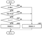
図9に示すフローチャートのステップS901からS909までの各判定または制御の処理は、HV_ECU50の制御部によって行われる。
Each determination or control process from steps S901 to S909 in the flowchart shown in FIG. 9 is performed by the control unit of the
まず、ステップS901では、エンジン1が自立運転状態であるか否かが判定される。制御部は、アクセル開度センサの出力信号などに基づいてエンジンが自立運転をしている状態か否かを判定することができる。あるいは、制御部は、HV_ECU50においてエンジン1の自立運転制御が行われているときに、その制御指令に基づいてステップS901で自立運転状態であると判断することもできる。そして、エンジン1が自立運転状態でないときには、ステップS901で否定判定されて、次のステップS903で衝突音の発生を抑制するための抑制制御がOFFに設定された後に、当該ルーチンが終了される。この場合、抑制制御がOFFに設定されるので、接触部材102はパーキングギヤ86から離れた初期の位置に維持される。他方、エンジン1が自立運転状態であるときには、ステップS901で肯定判定されて、ステップS905に進む。なお、ここでは、エンジン1が自立運転状態であるものとしてステップS905に進む。
First, in step S901, it is determined whether or not the
ステップS905では、車速が所定速以下であるか否かが判定される。好ましくは、所定速は0km/hである。この車速は車速センサの出力に基づいて検出される。このステップS905は、車両の走行中に運転者が誤ってPレンジにシフトレバーを移動させた場合に衝突音の発生を抑制するための抑制制御が実行されるのを防ぐために設けられているものであり、場合によっては省いてもよい。車速が所定速を超えている、つまり走行状態であるときには、ステップS905で否定判定されて、上記で説明したステップS903へ進む。他方、車速が所定速以下であるときには、ステップS905で肯定判定されて、次のステップS907に進む。なお、ここでは、車速が所定速以下であるものとしてステップS907に進む。 In step S905, it is determined whether or not the vehicle speed is equal to or lower than a predetermined speed. Preferably, the predetermined speed is 0 km / h. This vehicle speed is detected based on the output of the vehicle speed sensor. This step S905 is provided to prevent the suppression control for suppressing the generation of the collision sound when the driver accidentally moves the shift lever to the P range while the vehicle is traveling. In some cases, it may be omitted. When the vehicle speed exceeds the predetermined speed, that is, when the vehicle is running, a negative determination is made in step S905, and the process proceeds to step S903 described above. On the other hand, when the vehicle speed is equal to or lower than the predetermined speed, an affirmative determination is made in step S905, and the process proceeds to the next step S907. Here, it is assumed that the vehicle speed is equal to or lower than the predetermined speed, and the process proceeds to step S907.
ステップS907では、Pレンジが選択されているか否かが判定される。シフトポジションセンサを用いて取得した情報の示す現在のシフトポジションがPレンジであるときには、ステップS907で肯定判定されて、次のステップS909に進む。他方、Pレンジでないときには、ステップS907で否定判定されて、上記で説明したステップS903へ進む。なお、ここでは、現在のシフトポジションがPレンジであるものとしてステップS909に進む。この場合、Pレンジであるため、パーキングロック機構80はパーキングロックポジション(噛合位置)にあり、パーキングロックポール87の爪部87aがパーキングギヤ86に噛み合っている。
In step S907, it is determined whether the P range is selected. When the current shift position indicated by the information acquired using the shift position sensor is in the P range, an affirmative determination is made in step S907 and the process proceeds to the next step S909. On the other hand, when it is not in the P range, a negative determination is made in step S907, and the process proceeds to step S903 described above. Here, assuming that the current shift position is in the P range, the process proceeds to step S909. In this case, since it is the P range, the
ステップS909では、衝突音の発生を抑制するための抑制制御がONに設定される。即ち、抑制制御が実行される。具体的には、抑制制御が実行されるように、HV_ECU50の制御部が、接触部材102をパーキングギヤ86に接させるように、それを駆動するアクチュエータ114に対して作動信号を出力する。これにより、接触部材102がパーキングギヤ86に押し付けられるので、第4実施形態の構成においても、第1実施形態で述べたのと同様の作用効果が奏される。そして、当該ルーチンが終了される。なお、抑制制御の実行後再度本フローチャートの処理が実行された際に抑制制御の実行条件が成立しない場合には、HV_ECU50の制御部は、上記ステップS903の処理において、パーキングギヤ86に接している接触部材102をパーキングギヤ86から離して非接触とするように、それを駆動するアクチュエータ114に対して作動信号を出力する。
In step S909, the suppression control for suppressing the occurrence of the collision sound is set to ON. That is, suppression control is executed. Specifically, the control unit of the
このようなアクチュエータを用いた電子制御は、第2実施形態の板ばね状摩擦部材、および、第3実施形態のボール状部材の制御にも適用することができる。なお、これらの変形バージョンの更なる説明は省略する。 Electronic control using such an actuator can also be applied to control of the leaf spring-like friction member of the second embodiment and the ball-like member of the third embodiment. Further description of these modified versions is omitted.
本実施形態においては、上記ステップS901での判定により、抵抗付与部材(接触部材102等)が、自立運転中という必要なタイミングに限りリングギヤ部材13Rに接触するため、自立運転中以外の運転状態である場合にも接触するのと比べて接触時間を短くすることができ、即ち、接触による磨耗の機会を少なくできるので、抵抗付与部材の寿命を長くすることができる。
In the present embodiment, as a result of the determination in step S901, the resistance applying member (
[第5実施形態]
図10を参照して、本発明の第5実施形態について説明する。第5実施形態は、抵抗付与装置の構成の点で、上記実施形態のいずれとも相違する。そこで、以下では、上記実施形態の説明を参照することにより当業者であれば明らかである点については説明を省略または簡潔に行い、第5実施形態の特徴的な構成および機能について説明する。以下の説明では、上記実施形態の説明において既に説明した構成要素と同様の機能を有する構成要素には、同様の符号を付して重複説明を省略する。ただし、上記実施形態において説明されたような修正および変更は、矛盾しない限り、第5実施形態にも同様に適用される。
[Fifth Embodiment]
A fifth embodiment of the present invention will be described with reference to FIG. The fifth embodiment is different from any of the above embodiments in terms of the configuration of the resistance applying device. Therefore, in the following description, the features that are obvious to those skilled in the art by referring to the description of the above embodiment will be omitted or briefly described, and the characteristic configuration and function of the fifth embodiment will be described. In the following description, components having the same functions as those already described in the description of the above embodiment are given the same reference numerals, and redundant description is omitted. However, the modifications and changes described in the above embodiment are similarly applied to the fifth embodiment as long as there is no contradiction.
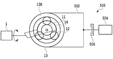
第5実施形態の抵抗付与装置500は、リングギヤ13と一体回転するように設けられた回転抑制部材502と、抵抗付与部材としてのクラッチ506と、駆動装置504とを備えている。クラッチ506は、回転抑制部材502に連結されてそれと一体回転する被押圧部材である回転体と、被押圧部材に当接することによって生ずる摩擦力により、被押圧部材に対して回転を抑制するように回転抵抗を与える押圧部材とを有しており、その被押圧部材に対する押圧部材の当接または非当接の動作が油圧によって制御されるようになっている。駆動装置504は、クラッチ506での被押圧部材に対する押圧部材の当接および非当接の動作を、HV_ECU50からの制御信号に基づき油圧によって制御する油圧アクチュエータを有している。そのため、第5実施形態でも、第4実施形態と同様に、パーキングロックポール87がパーキングロックポジション(噛合位置)に動かされるとき、パーキングロックポール87の動きに連動して直接回転抑制部材502に機械的な力が及ぶことはない。また、第5実施形態でも、第4実施形態と同様に、図9のフローチャートに沿った制御が実行され、ステップS909で衝突音の発生を抑制するための抑制制御が実行されるとき、HV_ECU50からの制御信号に基づき駆動装置504が作動する。この油圧アクチュエータの作動によって、回転抑制部材502に回転抵抗を与えるべく、回転抑制部材502に連結された被押圧部材(回転体)に対して押圧部材を当接させるように、クラッチ506に油圧が及ぼされる。これにより、クラッチ506の押圧部材が被押圧部材(回転体)に当接(接触)し、その摩擦力により被押圧部材が連結された回転抑制部材502に回転抵抗が与えられる。そのため、回転抑制部材502と一体回転するリングギヤ13の回転が抑制されて、リングギヤ部材13Rの動きが抑制される。なお、回転抑制部材502は第3回転要素であるリングギヤ13の一部であり、この回転抑制部材502に連結された被押圧部材(回転体)に対して抵抗付与部材であるクラッチ506の押圧部材が接触(当接)するということは、抵抗付与部材が第3回転要素に対して接触するということである。
A
よって、第5実施形態においても、パーキングロックポール87の爪部87aとパーキングギヤ86との間での衝突音の発生を抑制することができ、さらに、リングギヤ部材13Rのカウンタドライブギヤ25とカウンタドリブンギヤ26との噛み合い箇所での衝突音の発生も抑制できる。なお、このように、回転抑制部材502に回転抵抗を与えるときには、Pレンジが選択されているので、パーキングロックポール87がパーキングロックポジション(噛合位置)に動かされて、その爪部87aがパーキングギヤ86に噛み合っている。
Therefore, also in the fifth embodiment, it is possible to suppress the occurrence of a collision sound between the
なお、上記の各実施形態においては、パーキングロックポール87の爪部87aとパーキングギヤ86との噛み合いの状態によって、抵抗付与部材のリングギヤ部材13Rに対する押し当ての強度を変更するようにしてもよい。具体的には、爪部87aがパーキングギヤ86に噛み合っていない状態(車両が停車している場合に限る)においては抵抗付与部材が第3回転要素であるリングギヤ部材13Rに弱い力で接触し、他方、爪部87aがパーキングギヤ86に噛み合っている状態においては抵抗付与部材がリングギヤ部材13Rに強い力で接触するように押し当ての強度を変更するようにする。
In each of the above embodiments, the strength of pressing the resistance applying member against the
上記では、ハイブリッド車両において、パーキングレンジが選択されてパーキング機構が働いているときに、エンジンのトルク変動に基づく、パーキング機構における歯打ち音の発生を抑制する方法について述べたが、ここで、再び、本発明が解決しようとする歯打ち音の発生についてその要因を述べる。 In the above, in the hybrid vehicle, when the parking range is selected and the parking mechanism is working, the method for suppressing the generation of rattling noise in the parking mechanism based on the torque fluctuation of the engine has been described. The cause of the occurrence of rattling noise to be solved by the present invention will be described.
歯打ち音の発生は、回転電機が発生させるガタ詰めトルクを第3回転要素に伝達させるとき、第3回転要素と回転電機との間のギヤの噛み合い部分のガタが詰まる前、つまり回転電機のトルクが第3回転要素に伝わる前に、回転電機と駆動輪との間のギヤの噛み合い部分のガタが詰まり、回転電機のトルクが駆動輪にのみ伝わる状態になることが要因である。 The generation of rattling noise occurs when the backlash torque generated by the rotating electrical machine is transmitted to the third rotating element, before the gear engaging portion between the third rotating element and the rotating electrical machine is clogged, that is, This is because before the torque is transmitted to the third rotating element, the backlash of the meshing portion of the gear between the rotating electrical machine and the driving wheel is clogged, and the torque of the rotating electrical machine is transmitted only to the driving wheel.
即ち、図1に示した第1実施形態のハイブリッド車両の動力伝達系においては、カウンタドライブギヤ25とカウンタドリブンギヤ26との間のガタが詰まる前に、ドライブピニオンギヤ28とデフリングギヤ29との間のガタが詰まる構成である。この場合、既述のとおり、第2回転電機MG2の回転軸34から出力されるガタ詰めトルクは、カウンタドリブンギヤ26を介してカウンタドライブギヤ25に伝達される前に、カウンタドリブンギヤ26及びドライブピニオンギヤ28を介して、駆動輪Wに伝達されることになる。そのため、カウンタドライブギヤ25とカウンタドリブンギヤ26との噛み合い箇所で歯打ち音(衝突音)が生じることとなるが、上記の各抑制手法を用いることにより、それらの噛み合い箇所での歯打ち音の発生を抑制することができる。
That is, in the power transmission system of the hybrid vehicle of the first embodiment shown in FIG. 1, before the backlash between the
なお、第3回転要素と、駆動輪と、回転電機の回転軸と、の間に介在して動力を伝達する本発明の歯車とは、回転電機が発生させたトルクを、第3回転要素に伝えるための歯車と、駆動輪に伝えるための歯車と、のそれぞれを指している。即ち、本発明の歯車とは、(第3回転要素のリングギヤ13と一体回転する)カウンタドライブギヤ25と、駆動輪Wと、第2回転電機MG2の回転軸34と、の間に介在して動力を伝達する歯車である。第1実施形態のハイブリッド車両の動力伝達系においては、第3回転要素にトルクを伝えるカウンタドリブンギヤ26と、駆動輪Wにトルクを伝えるドライブピニオンギヤ28と、が本発明の歯車に相当する。
Note that the gear of the present invention that transmits power through the third rotating element, the drive wheel, and the rotating shaft of the rotating electrical machine transmits torque generated by the rotating electrical machine to the third rotating element. Each of the gear for transmitting and the gear for transmitting to the driving wheel is indicated. That is, the gear of the present invention is interposed between the counter drive gear 25 (which rotates integrally with the
ところで、上記の第1実施形態で示した動力伝達系を一部変形した構成においても歯打ち音が発生するケースがある。以下、その歯打ち音が発生する動力伝達系の変形例の各構成について説明する。なお、以下では、第1実施形態の説明を参照することにより当業者であれば明らかである点については説明を省略または簡潔に行い、各変形例の特徴的な構成について説明する。第1実施形態の説明において既に説明した構成要素と同様の機能を有する構成要素には、同様の符号を付して重複説明を省略する。ただし、上記において説明されたような修正および変更は、矛盾しない限り、以下の各変形例にも同様に適用される。 Incidentally, there is a case where rattling noise is generated even in a configuration in which the power transmission system shown in the first embodiment is partially deformed. Hereinafter, each structure of the modification of the power transmission system which generates the rattling noise will be described. In the following, the description will be omitted or briefly given to those skilled in the art by referring to the description of the first embodiment, and the characteristic configuration of each modification will be described. Components having the same functions as those already described in the description of the first embodiment are denoted by the same reference numerals, and redundant description is omitted. However, the modifications and changes described above are similarly applied to the following modifications as long as there is no contradiction.
[動力伝達系の変形例1]
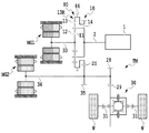
図11のスケルトン図を参照して、変形例1のハイブリッド車両の動力伝達系について説明する。変形例1は、第2回転電機MG2のリダクションギヤ35が、リングギヤ部材13Rに直接噛み合う構成の一例である。
[
With reference to the skeleton diagram of FIG. 11, the power transmission system of the hybrid vehicle of
図11に示すとおり、変形例1のハイブリッド車両の動力伝達系においては、リングギヤ部材13Rのカウンタドライブギヤ25が、リダクションギヤ35と噛み合っている。このリダクションギヤ35は、第2回転電機MG2の回転軸34に固定されている。また該回転軸34には、差動装置30のデフリングギヤ29と噛み合うドライブピニオンギヤ28が固定されている。これにより、リングギヤ13は、カウンタドライブギヤ25、リダクションギヤ35を介して第2回転電機MG2の回転軸34に接続されると同時に、該回転軸34、ドライブピニオンギヤ28、差動装置30および駆動軸31を介して駆動輪Wと接続されている。そのため、第2回転電機MG2の回転軸34から出力されるトルク(動力)は、ドライブピニオンギヤ28を介して駆動輪Wに伝達される。それと同時に、第2回転電機MG2の回転軸34から出力されるトルク(動力)はリダクションギヤ35を介してリングギヤ部材13Rのカウンタドライブギヤ25(およびリングギヤ13)にも伝達される。
As shown in FIG. 11, in the power transmission system of the hybrid vehicle of the first modification, the
上記のような変形例1のハイブリッド車両の動力伝達系においては、カウンタドライブギヤ25とリダクションギヤ35との間のガタが詰まる前に、ドライブピニオンギヤ28とデフリングギヤ29との間のガタが詰まる構成である。この場合、第2回転電機MG2の回転軸34から出力されるガタ詰めトルクは、リダクションギヤ35を介してカウンタドライブギヤ25に伝達される前に、ドライブピニオンギヤ28を介して、駆動輪Wに伝達されることになる。そのため、カウンタドライブギヤ25とリダクションギヤ35との噛み合い箇所で歯打ち音が生じることとなるが、上記の各抑制手法を用いることにより、それらの噛み合い箇所での歯打ち音の発生を抑制することができる。
In the power transmission system of the hybrid vehicle of
なお、本発明の歯車とは、カウンタドライブギヤ25と、駆動輪Wと、第2回転電機MG2の回転軸34と、の間に介在して動力を伝達する歯車であり、変形例1のハイブリッド車両の動力伝達系においては、第3回転要素にトルクを伝えるリダクションギヤ35と、駆動輪Wにトルクを伝えるドライブピニオンギヤ28と、に相当する。
Note that the gear of the present invention is a gear that is interposed between the
[動力伝達系の変形例2]
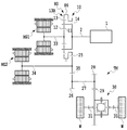
図12のスケルトン図を参照して、変形例2のハイブリッド車両の動力伝達系について説明する。この変形例2も、第2回転電機MG2のリダクションギヤ35が、リングギヤ部材13Rに直接噛み合う構成の一例である。
[
With reference to the skeleton diagram of FIG. 12, the power transmission system of the hybrid vehicle of
図12に示すとおり、変形例2のハイブリッド車両の動力伝達系においては、リングギヤ部材13Rのカウンタドライブギヤ25が、リダクションギヤ35と噛み合っている。このリダクションギヤ35は、第2回転電機MG2の回転軸34に固定されている。また、リダクションギヤ35には、カウンタドリブンギヤ26が噛み合っている。カウンタドリブンギヤ26は、カウンタシャフト27を介して差動装置30のデフリングギヤ29と噛み合うドライブピニオンギヤ28と接続されている。カウンタドリブンギヤ26とドライブピニオンギヤ28とは、一体回転するようになっている。これにより、リングギヤ13は、カウンタドライブギヤ25、リダクションギヤ35を介して第2回転電機MG2の回転軸34に接続されると同時に、該リダクションギヤ35、カウンタドリブンギヤ26、ドライブピニオンギヤ28、差動装置30および駆動軸31を介して駆動輪Wと接続されている。そのため、第2回転電機MG2の回転軸34から出力されるトルク(動力)は、リダクションギヤ35、カウンタドリブンギヤ26、ドライブピニオンギヤ28を介して駆動輪Wに伝達される。それと同時に、第2回転電機MG2の回転軸34から出力されるトルク(動力)はリダクションギヤ35を介してリングギヤ部材13Rのカウンタドライブギヤ25(およびリングギヤ13)にも伝達される。
As shown in FIG. 12, in the power transmission system of the hybrid vehicle according to the second modification, the
上記のような変形例2のハイブリッド車両の動力伝達系においては、カウンタドライブギヤ25とリダクションギヤ35との間のガタが詰まる前に、リダクションギヤ35とカウンタドリブンギヤ26との間のガタが詰まる構成である。この場合、第2回転電機MG2の回転軸34から出力されるガタ詰めトルクは、リダクションギヤ35を介してカウンタドライブギヤ25に伝達される前に、リダクションギヤ35およびカウンタドリブンギヤ26を介して、駆動輪Wに伝達されることになる。そのため、カウンタドライブギヤ25とリダクションギヤ35との噛み合い箇所で歯打ち音が生じることとなるが、上記の各抑制手法を用いることにより、それらの噛み合い箇所での歯打ち音の発生を抑制することができる。
In the power transmission system of the hybrid vehicle of
なお、本発明の歯車とは、カウンタドライブギヤ25と、駆動輪Wと、第2回転電機MG2の回転軸34と、の間に介在して動力を伝達する歯車であり、変形例2のハイブリッド車両の動力伝達系においては、第3回転要素および駆動輪Wにトルクを伝えるリダクションギヤ35に相当する。
The gear of the present invention is a gear that transmits power through the
[動力伝達系の変形例3]
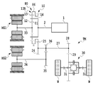
図13のスケルトン図を参照して、変形例3のハイブリッド車両の動力伝達系について説明する。変形例3は、第2回転電機MG2のリダクションギヤ35が、カウンタシャフト27に設けたカウンタドリブンギヤ26以外のギヤに噛み合う構成の一例である。
[Modification 3 of the power transmission system]
With reference to the skeleton diagram of FIG. 13, the power transmission system of the hybrid vehicle of Modification 3 will be described. Modification 3 is an example of a configuration in which the
図13に示すとおり、変形例3のハイブリッド車両の動力伝達系においては、リングギヤ部材13Rのカウンタドライブギヤ25が、カウンタドリブンギヤ26と噛み合っている。カウンタドリブンギヤ26は、カウンタシャフト27を介して差動装置30のデフリングギヤ29と噛み合うドライブピニオンギヤ28と接続されている。またカウンタドリブンギヤ26は、カウンタシャフト27を介してリダクションギヤ35と噛み合う第2カウンタドリブンギヤ36とも接続されている。カウンタドリブンギヤ26、第2カウンタドリブンギヤ36およびドライブピニオンギヤ28は、一体回転するようになっている。リダクションギヤ35には、第2回転電機MG2の回転軸34が固定されている。これにより、リングギヤ13は、カウンタドライブギヤ25、カウンタドリブンギヤ26ドライブピニオンギヤ28、差動装置30および駆動軸31を介して駆動輪Wと接続されている。また、第2回転電機MG2の回転軸34は、リングギヤ13と駆動輪Wとの間の動力伝達経路に対し、カウンタドリブンギヤ26を介して接続されており、リングギヤ13および駆動輪Wのそれぞれにトルク(動力)を伝達することが可能となっている。そのため、第2回転電機MG2の回転軸34から出力されるトルク(動力)は、ドライブピニオンギヤ28を介して駆動輪Wに伝達される。それと同時に、第2回転電機MG2の回転軸34から出力されるトルク(動力)はカウンタドリブンギヤ26を介してリングギヤ部材13Rのカウンタドライブギヤ25(およびリングギヤ13)にも伝達される。
As shown in FIG. 13, in the power transmission system of the hybrid vehicle of Modification 3, the
上記のような変形例3のハイブリッド車両の動力伝達系においては、カウンタドライブギヤ25とカウンタドリブンギヤ26との間のガタが詰まる前に、ドライブピニオンギヤ28とデフリングギヤ29との間のガタが詰まる構成である。この場合、第2回転電機MG2の回転軸34から出力されるガタ詰めトルクは、カウンタドリブンギヤ26を介してカウンタドライブギヤ25に伝達される前に、ドライブピニオンギヤ28を介して、駆動輪Wに伝達されることになる。そのため、カウンタドライブギヤ25とカウンタドリブンギヤ26との噛み合い箇所で歯打ち音が生じることとなるが、上記の各抑制手法を用いることにより、それらの噛み合い箇所での歯打ち音の発生を抑制することができる。
In the power transmission system of the hybrid vehicle of Modification 3 as described above, the backlash between the
なお、本発明の歯車とは、カウンタドライブギヤ25と、駆動輪Wと、第2回転電機MG2の回転軸34と、の間に介在して動力を伝達する歯車であり、変形例3のハイブリッド車両の動力伝達系においては、第3回転要素にトルクを伝えるカウンタドリブンギヤ26と、駆動輪Wにトルクを伝えるドライブピニオンギヤ28と、に相当する。
The gear of the present invention is a gear that transmits power through the
本発明の実施形態は上述した実施形態のみに限られない。特許請求の範囲によって規定される本発明の思想に包含されるあらゆる変形例や応用例、均等物が本発明に含まれる。 Embodiments of the present invention are not limited to the above-described embodiments. All modifications, applications, and equivalents included in the spirit of the present invention defined by the claims are included in the present invention.
1 エンジン、MG1 第1回転電機、MG2 第2回転電機、TM 動力伝達装置、10 遊星歯車機構、11 サンギヤ、12 プラネタリギヤ、13 リングギヤ、13R リングギヤ部材、14 キャリア、25 カウンタドライブギヤ、26 カウンタドリブンギヤ、35 リダクションギヤ、50 HV_ECU、80 パーキングロック機構、86 パーキングギヤ、86a 歯、87 パーキングロックポール(パーキング噛合部材)、87a 爪部、100,100’,200,300,500 抵抗付与装置、102 接触部材(抵抗付与部材)、114 アクチュエータ、202 板ばね状摩擦部材(抵抗付与部材)、204 円環状部、302 ボール状部材(抵抗付与部材)、502 回転抑制部材、506 クラッチ(抵抗付与部材)。 1 engine, MG1 first rotating electrical machine, MG2 second rotating electrical machine, TM power transmission device, 10 planetary gear mechanism, 11 sun gear, 12 planetary gear, 13 ring gear, 13R ring gear member, 14 carrier, 25 counter drive gear, 26 counter driven gear, 35 reduction gear, 50 HV_ECU, 80 parking lock mechanism, 86 parking gear, 86a teeth, 87 parking lock pole (parking engagement member), 87a claw, 100, 100 ′, 200, 300, 500 resistance applying device, 102 contact member (Resistance applying member), 114 actuator, 202 leaf spring friction member (resistance applying member), 204 annular portion, 302 ball member (resistance applying member), 502 rotation suppression member, 506 clutch (resistance applying portion) ).
Claims (7)
エンジンに連結された第1回転要素と、第2回転要素と、回転電機および駆動輪に動力伝達可能に連結された第3回転要素と、を備える遊星歯車機構と、
前記第3回転要素と、前記駆動輪と、前記回転電機の回転軸と、の間に介在して動力を伝達する歯車と、
前記第3回転要素と一体回転するように設けられたパーキングギヤと、該パーキングギヤに噛み合うことができる爪部を有し、パーキングレンジの選択状態に応じて前記爪部が前記パーキングギヤに対して噛み合っている状態と噛み合っていない状態とを切り替えるように動作するパーキング噛合部材と、を備えるパーキングロック機構と、
前記パーキングギヤまたは前記第3回転要素に対して接触することにより、前記パーキングギヤまたは前記第3回転要素へ回転抵抗を与えることができる抵抗付与部材を有し、前記パーキング噛合部材の前記爪部が前記パーキングギヤに噛み合っている状態においては、噛み合っていない状態に比べて前記回転抵抗を大きくするように、前記パーキングギヤまたは前記第3回転要素に前記抵抗付与部材を接触させる抵抗付与装置と、
を備えたハイブリッド車両の動力伝達装置。 A power transmission device for a hybrid vehicle,
A planetary gear mechanism comprising: a first rotating element coupled to the engine; a second rotating element; and a third rotating element coupled to the rotating electrical machine and the driving wheel so as to be capable of transmitting power.
A gear that is interposed between the third rotating element, the driving wheel, and a rotating shaft of the rotating electrical machine to transmit power;
A parking gear provided to rotate integrally with the third rotating element; and a claw portion capable of meshing with the parking gear, wherein the claw portion is connected to the parking gear according to a selected state of a parking range. A parking lock member that operates to switch between a meshed state and a non-engaged state; and a parking lock mechanism comprising:
A resistance applying member capable of giving a rotational resistance to the parking gear or the third rotating element by contacting the parking gear or the third rotating element; and the pawl portion of the parking meshing member A resistance applying device for bringing the resistance applying member into contact with the parking gear or the third rotating element so as to increase the rotational resistance in a state in which the parking gear is engaged, compared to a state in which the parking gear is not engaged;
A power transmission device for a hybrid vehicle comprising:
ことを特徴とする請求項1に記載のハイブリッド車両の動力伝達装置。 The resistance applying member is interlocked with the operation of the parking meshing member, and is separated from the parking gear or the third rotating element when the pawl is not meshed with the parking gear, and the pawl is connected to the parking gear. In the engaged state, it contacts the parking gear or the third rotating element,
The power transmission device for a hybrid vehicle according to claim 1.
ことを特徴とする請求項2に記載のハイブリッド車両の動力伝達装置。 The resistance applying member is mechanically coupled to the parking engagement member.
The power transmission device for a hybrid vehicle according to claim 2.
該制御部は、前記爪部が前記パーキングギヤに噛み合っている状態において、前記爪部が前記パーキングギヤに噛み合っていない状態に比べて、前記抵抗付与部材が前記パーキングギヤまたは前記第3回転要素に与える前記回転抵抗を大きくするように前記駆動部を作動させる、
ことを特徴とする請求項1に記載のハイブリッド車両の動力伝達装置。 The resistance applying device further includes a drive unit that drives the resistance applying member so as to change a contact state with the parking gear or the third rotating element, and a control unit that controls the operation of the drive unit. ,
In the state where the claw portion is engaged with the parking gear, the control unit is configured such that the resistance applying member is connected to the parking gear or the third rotating element compared to a state where the claw portion is not engaged with the parking gear. Actuating the drive unit to increase the rotational resistance applied;
The power transmission device for a hybrid vehicle according to claim 1.
ことを特徴とする請求項4に記載のハイブリッド車両の動力伝達装置。 The control unit operates the drive unit so as to increase the rotation resistance that the resistance applying member gives to the parking gear or the third rotation element when the engine is operating independently.
The power transmission device for a hybrid vehicle according to claim 4.
ことを特徴とする請求項1に記載のハイブリッド車両の動力伝達装置。 The resistance applying member is interlocked with the operation of the parking meshing member, and contacts the tooth surface of the tooth gap different from the tooth groove of the tooth surface with which the pawl portion meshes with the pawl portion meshing with the parking gear. To
The power transmission device for a hybrid vehicle according to claim 1.
前記抵抗付与部材は、前記回転抑制部材に接触することにより、前記第3回転要素へ前記回転抵抗を与えることができ、
前記抵抗付与装置は、前記爪部が前記パーキングギヤに噛み合っている状態において、前記爪部が前記パーキングギヤに噛み合っていない状態に比べて、前記第3回転要素へ与える前記回転抵抗を大きくするように前記抵抗付与部材を作動させる、
ことを特徴とする請求項1に記載のハイブリッド車両の動力伝達装置。 The third rotating element further includes a rotation suppressing member provided to rotate integrally with the parking gear,
The resistance applying member can give the rotation resistance to the third rotating element by contacting the rotation suppressing member,
The resistance applying device increases the rotational resistance applied to the third rotating element in a state where the claw portion is engaged with the parking gear, compared to a state where the claw portion is not engaged with the parking gear. Actuating the resistance applying member
The power transmission device for a hybrid vehicle according to claim 1.
Priority Applications (11)
| Application Number | Priority Date | Filing Date | Title |
|---|---|---|---|
| US15/480,541 US20170299055A1 (en) | 2016-04-13 | 2017-04-06 | Transmission system for hybrid electric vehicle |
| BR102017007107-3A BR102017007107A2 (en) | 2016-04-13 | 2017-04-06 | TRANSMISSION SYSTEM FOR HYBRID ELECTRIC VEHICLE |
| MX2017004719A MX2017004719A (en) | 2016-04-13 | 2017-04-10 | Transmission system for hybrid electric vehicle. |
| TW106111918A TW201736160A (en) | 2016-04-13 | 2017-04-10 | Transmission system for hybrid electric vehicle |
| KR1020170046125A KR20170117327A (en) | 2016-04-13 | 2017-04-10 | Transmission system for hybrid electric vehicle |
| CN201710228831.8A CN107298016A (en) | 2016-04-13 | 2017-04-10 | The power transmission of motor vehicle driven by mixed power |
| AU2017202403A AU2017202403A1 (en) | 2016-04-13 | 2017-04-11 | Transmission system for hybrid electric vehicle |
| CA2964066A CA2964066A1 (en) | 2016-04-13 | 2017-04-11 | Transmission system for hybrid electric vehicle |
| RU2017112341A RU2017112341A (en) | 2016-04-13 | 2017-04-11 | TRANSMISSION SYSTEM FOR HYBRID ELECTRIC VEHICLE |
| EP17166293.5A EP3231652A1 (en) | 2016-04-13 | 2017-04-12 | Transmission system for hybrid electric vehicle |
| PH12017000131A PH12017000131A1 (en) | 2016-04-13 | 2017-04-12 | Transmission system for hybrid electric vehicle |
Applications Claiming Priority (2)
| Application Number | Priority Date | Filing Date | Title |
|---|---|---|---|
| JP2016080412 | 2016-04-13 | ||
| JP2016080412 | 2016-04-13 |
Publications (1)
| Publication Number | Publication Date |
|---|---|
| JP2017193322A true JP2017193322A (en) | 2017-10-26 |
Family
ID=60154613
Family Applications (1)
| Application Number | Title | Priority Date | Filing Date |
|---|---|---|---|
| JP2016195885A Withdrawn JP2017193322A (en) | 2016-04-13 | 2016-10-03 | Hybrid-vehicular power transmission apparatus |
Country Status (8)
| Country | Link |
|---|---|
| JP (1) | JP2017193322A (en) |
| KR (1) | KR20170117327A (en) |
| AU (1) | AU2017202403A1 (en) |
| BR (1) | BR102017007107A2 (en) |
| MX (1) | MX2017004719A (en) |
| PH (1) | PH12017000131A1 (en) |
| RU (1) | RU2017112341A (en) |
| TW (1) | TW201736160A (en) |
Cited By (1)
| Publication number | Priority date | Publication date | Assignee | Title |
|---|---|---|---|---|
| JP2020199950A (en) * | 2019-06-12 | 2020-12-17 | トヨタ自動車株式会社 | Hybrid vehicle |
Families Citing this family (3)
| Publication number | Priority date | Publication date | Assignee | Title |
|---|---|---|---|---|
| TWI768845B (en) * | 2021-04-23 | 2022-06-21 | 張勛 | power generation device |
| DE112022005086T5 (en) * | 2021-10-23 | 2024-09-12 | Nextgen Tech Initiatives Pvt. Ltd. | PLANETARY GEAR-BASED ELECTRIC HYBRID DRIVE SYSTEM FOR A VEHICLE |
| US12515514B1 (en) | 2024-12-14 | 2026-01-06 | Nextgen Tech Initiatives Pvt Ltd | Hybrid electric drive system for a vehicle |
Family Cites Families (7)
| Publication number | Priority date | Publication date | Assignee | Title |
|---|---|---|---|---|
| FR2814989B1 (en) * | 2000-10-11 | 2004-12-03 | Renault | HYBRID DRIVE UNIT COMPRISING BRAKING MEANS |
| JP5012215B2 (en) * | 2007-05-24 | 2012-08-29 | トヨタ自動車株式会社 | Control device for shift switching mechanism |
| US8684880B2 (en) * | 2009-03-11 | 2014-04-01 | Toyota Jidosha Kabushiki Kaisha | Rattling noise reduction device for vehicle |
| CN102463886B (en) * | 2010-11-04 | 2015-04-15 | 上海捷能汽车技术有限公司 | Hybrid power transmission system and control method thereof |
| JP5790792B2 (en) * | 2012-01-24 | 2015-10-07 | トヨタ自動車株式会社 | Hybrid system |
| PH12012000030A1 (en) * | 2012-02-07 | 2013-08-12 | H2O Tech Phils Inc | A hybrid vehicle |
| DE102014114889A1 (en) * | 2013-10-15 | 2015-04-16 | Toyota Jidosha Kabushiki Kaisha | Drive unit for vehicles |
-
2016
- 2016-10-03 JP JP2016195885A patent/JP2017193322A/en not_active Withdrawn
-
2017
- 2017-04-06 BR BR102017007107-3A patent/BR102017007107A2/en not_active IP Right Cessation
- 2017-04-10 KR KR1020170046125A patent/KR20170117327A/en not_active Ceased
- 2017-04-10 MX MX2017004719A patent/MX2017004719A/en unknown
- 2017-04-10 TW TW106111918A patent/TW201736160A/en unknown
- 2017-04-11 RU RU2017112341A patent/RU2017112341A/en not_active Application Discontinuation
- 2017-04-11 AU AU2017202403A patent/AU2017202403A1/en not_active Abandoned
- 2017-04-12 PH PH12017000131A patent/PH12017000131A1/en unknown
Cited By (2)
| Publication number | Priority date | Publication date | Assignee | Title |
|---|---|---|---|---|
| JP2020199950A (en) * | 2019-06-12 | 2020-12-17 | トヨタ自動車株式会社 | Hybrid vehicle |
| JP7230700B2 (en) | 2019-06-12 | 2023-03-01 | トヨタ自動車株式会社 | hybrid vehicle |
Also Published As
| Publication number | Publication date |
|---|---|
| AU2017202403A1 (en) | 2017-11-02 |
| RU2017112341A (en) | 2018-10-11 |
| TW201736160A (en) | 2017-10-16 |
| RU2017112341A3 (en) | 2018-10-11 |
| BR102017007107A2 (en) | 2017-10-17 |
| PH12017000131A1 (en) | 2019-01-28 |
| KR20170117327A (en) | 2017-10-23 |
| MX2017004719A (en) | 2018-08-16 |
Similar Documents
| Publication | Publication Date | Title |
|---|---|---|
| EP3231652A1 (en) | Transmission system for hybrid electric vehicle | |
| JP5638075B2 (en) | Driving system for automobile and control method thereof | |
| US9096219B2 (en) | Drive apparatus for hybrid vehicle | |
| CN102348914B (en) | Rattling noise preventing device for vehicle | |
| US20140213410A1 (en) | Vehicle parking apparatus and method for parking vehicle | |
| JP6841051B2 (en) | Vehicles with power transmission and power transmission | |
| JP4029875B2 (en) | Vehicle control device | |
| JP6135418B2 (en) | Power transmission device for hybrid vehicle | |
| JP2019156016A (en) | Drive device of hybrid vehicle | |
| KR20170117327A (en) | Transmission system for hybrid electric vehicle | |
| JP2011178280A (en) | Power transmission device for hybrid vehicle and control method for the same | |
| JP5930121B2 (en) | Engagement device and power transmission device | |
| JP6406154B2 (en) | Control device for vehicle power transmission device | |
| WO2012077380A1 (en) | Power transmission control device for vehicle | |
| US9776627B2 (en) | Hybrid vehicle driving device | |
| CN110155037B (en) | Vehicle drive control device and vehicle control method | |
| JP2021080981A (en) | Control device of power transmission mechanism | |
| WO2012002062A1 (en) | Driving system for automobile and method for controlling same | |
| JP2020138581A (en) | Hybrid vehicle drive | |
| JP2018158630A (en) | Power transmission device for hybrid vehicle | |
| JP6048256B2 (en) | Hybrid vehicle drive device | |
| JP2009132191A (en) | Control device for hybrid drive device for vehicle |
Legal Events
| Date | Code | Title | Description |
|---|---|---|---|
| A621 | Written request for application examination |
Free format text: JAPANESE INTERMEDIATE CODE: A621 Effective date: 20180125 |
|
| A761 | Written withdrawal of application |
Free format text: JAPANESE INTERMEDIATE CODE: A761 Effective date: 20180219 |