JP2017193347A - Multipack package - Google Patents
Multipack package Download PDFInfo
- Publication number
- JP2017193347A JP2017193347A JP2016084216A JP2016084216A JP2017193347A JP 2017193347 A JP2017193347 A JP 2017193347A JP 2016084216 A JP2016084216 A JP 2016084216A JP 2016084216 A JP2016084216 A JP 2016084216A JP 2017193347 A JP2017193347 A JP 2017193347A
- Authority
- JP
- Japan
- Prior art keywords
- top plate
- piece
- plate
- side plate
- sides
- Prior art date
- Legal status (The legal status is an assumption and is not a legal conclusion. Google has not performed a legal analysis and makes no representation as to the accuracy of the status listed.)
- Pending
Links
Images



Landscapes
- Packages (AREA)
Abstract
Description
この発明は、飲料缶を複数本纏めて持ち運べるように包装する板紙製のマルチパック包装体に関するものである。 The present invention relates to a multi-pack package made of paperboard that wraps a plurality of beverage cans so that they can be carried together.
従来より、ビール等の飲料入りの缶の包装用として、図6に示すようなマルチパック包装体が使用されている(下記特許文献1参照)。このマルチパック包装体では、天板51の両側に側板52及び底板53が順次連設され、一方の底板53に差込片54及び係合片54aが、他方の底板53に差込穴55及び係合穴55aがそれぞれ設けられている。
Conventionally, a multi-pack package as shown in FIG. 6 has been used for packaging cans containing beverages such as beer (see
側板52の天板51寄りの端縁から折込片56が延出され、折込片56と天板51のコーナー部とが抱持片57で繋がれている。側板52と底板53の稜部には、固定片58が切込により形成され、固定片58の基部及び中間部には、幅方向に延びる折目線58a,58bがそれぞれ入れられている。
The
天板51には、運搬用の指入穴を形成する指押片60が切込により形成されると共に、開封時に切断して缶Cを取り出すため、一方の端縁から他方の端縁へかけて、鉤状の切目が断続するジッパ型の切目線61が2本入れられている。
A
このマルチパック包装体により集積した缶Cを包装する際には、缶Cの上面に天板51を被せ、両側の側板52を下方へ折り曲げ、底板53を内側へ折り曲げる。そして、底板53の係合片54aと係合穴55aを係合させ、差込片54を差込穴55へ差し込んで、底板53同士を連結し、スリーブ状に保形する。
When packaging the cans C collected by the multipack package, the
また、折込片56を内側へ折り込み、抱持片57を缶Cの上部外周に沿わせて、缶Cの上部を保持し、固定片58を折目線58a,58bを軸として互いに逆方向へ折り曲げ、固定片58の先端を缶Cの底面の凹部周縁に係合させ、缶Cの底部外周を側板52と底板53の境界部分に形成された抜穴59に嵌合させて、缶Cの下部を保持することにより、両端面の開口部から缶Cを抜け止めする。
Further, the
ところで、缶Cを包装したマルチパック包装体Mは、図7に示すように、4個1組としてラップラウンド形式の段ボール箱Bに詰められて配送される。その段ボール箱Bを積み上げる際、図8(a)に示すように、載せようとする段ボール箱Bを既に高く積み上げられた段ボール箱Bの上稜部にぶつけたり、図8(b)に示すように、下段側の段ボール箱Bの上稜部に衝突させたりすることがある。 By the way, as shown in FIG. 7, the multipack package M in which the cans C are packaged is packed in a cardboard box B in a wrap round format and delivered. When the cardboard boxes B are stacked, as shown in FIG. 8 (a), the cardboard boxes B to be placed are hit against the upper ridges of the cardboard boxes B that have already been stacked, as shown in FIG. 8 (b). In addition, it may collide with the upper ridge of the lower cardboard box B.
このような場合、段ボール箱Bの内部に収納されたマルチパック包装体Mに局所的に非常に大きな衝撃が作用し、図9(a)に示すように、底板53の稜部に抜穴59の両端縁から破れt1が生じたり、また、図9(b)に示すように、側板52と折込片56の繋部分に破れt2が生じたりすることがある。そして、このような破れが生じると、マルチパック包装体Mにより缶Cが保持されなくなる恐れがある。
In such a case, a very large impact is locally applied to the multi-pack package M accommodated in the cardboard box B, and the
そこで、この発明は、流通過程において、段ボール箱に詰められた状態で大きな衝撃が作用しても、缶の保持力が損なわれるような破れが生じにくいマルチパック包装体を提供することを課題とする。 Therefore, the present invention has an object to provide a multi-pack package that is unlikely to be broken so that the holding force of a can is impaired even if a large impact is applied in a state of being packed in a cardboard box in a distribution process. To do.
上記課題を解決するため、この発明は、天板の両側に側板及び底板が順次連設され、側板の天板寄りの両端から折込片が延出され、折込片と天板のコーナー部とが抱持片で繋がれ、両側の底板から側板の下部へかけて切込による固定片が形成され、固定片の基部及び中間部には、幅方向に延びる折目線がそれぞれ入れられ、
集積された複数本の缶が前記天板と両側の側板及び底板により包囲され、両側の底板が連結されてスリーブ状に保形され、
前記折込片が内側へ折り込まれ、前記抱持片が缶の上部外周に沿って缶の上部が保持され、前記固定片が基部及び中間部の折目線を軸として互いに逆方向へ折り曲げられ、固定片の先端が缶の底面の凹部周縁に係合して缶の下部が保持され、これにより、両端面の開口部から缶が抜け止めされるマルチパック包装体において、
前記天板と側板の境界の中央部又はその近傍に、両端面の開口部を結ぶ方向へ延びるように、かつ、いずれの端縁にも達しないように、切目と繋部が断続するミシン目状の弱め線が入れられているものとしたのである。
In order to solve the above-mentioned problem, the present invention is such that side plates and bottom plates are sequentially arranged on both sides of the top plate, folding pieces are extended from both ends of the side plate near the top plate, and the folding pieces and the corner portions of the top plate are provided. Connected by holding pieces, a fixed piece by cutting is formed from the bottom plate on both sides to the lower part of the side plate, and a crease line extending in the width direction is put in the base part and the intermediate part of the fixed piece, respectively.
A plurality of accumulated cans are surrounded by the top plate and side plates and bottom plates on both sides, and the bottom plates on both sides are connected and held in a sleeve shape,
The folded piece is folded inward, the holding piece is held at the upper part of the can along the upper outer periphery of the can, and the fixed piece is folded in the opposite direction around the fold line of the base and the middle part and fixed. In the multi-pack package in which the tip of the piece is engaged with the peripheral edge of the recess on the bottom of the can and the lower part of the can is held, thereby preventing the can from coming off from the opening on both ends.
A perforation in which the cut and the connecting portion are intermittently extended so as to extend in the direction connecting the openings of both end faces to the central portion of the boundary between the top plate and the side plate or in the vicinity thereof, and so as not to reach any end edge. It was assumed that a weak line of the shape was put.
この発明に係るマルチパック包装体では、段ボール箱に詰められた状態で荷扱い作業時に大きな衝撃が作用しても、缶の保持にはあまり影響のない天板と側板の境界の中央部又はその近傍に入れられた弱め線で切目間の繋部が破断することにより、衝撃が吸収されるので、缶の保持力が損なわれるような破れが生じにくい。 In the multi-pack package according to the present invention, even when a large impact is applied during the handling operation in a state of being packed in a cardboard box, the central portion of the boundary between the top plate and the side plate or the side plate which does not significantly affect the holding of the can Since the joint between the cuts breaks at the weak line put in the vicinity, the impact is absorbed, so that it is difficult to cause a tear that impairs the holding power of the can.
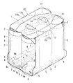
最初に、この発明の第1実施形態を図1〜図3に基づいて説明する。 First, a first embodiment of the present invention will be described with reference to FIGS.
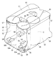
図1に示すマルチパック包装体は、ビール等の飲料入りの缶Cを6本の纏めて持ち運べるように、3本ずつ2列に纏めて包装するものであり、図2に示すような耐水性板紙のブランクから形成される。 The multi-pack package shown in FIG. 1 wraps three cans C in two rows so that six cans C containing beer can be carried together, and is water resistant as shown in FIG. It is formed from a paperboard blank.
このブランクでは、天板1の両側にそれぞれ側板2及び底板3が順次連設され、一方の底板3に差込片4及び係合片4aが、他方の底板3に差込穴5及び係合穴5aがそれぞれ設けられている。差込穴5はスリット状であり、差込穴5に臨んで押込片5bが切込により形成されている。
In this blank, the
側板2の天板1寄りの両端辺には折込片6が連設され、折込片6と天板1のコーナー部とは抱持片7で繋がれている。
Folding
底板3から側板2の下部となる部分にかけては、先端が丸みを帯びた固定片8が切込により3個ずつ形成され、固定片8の基部及び中間部には、幅方向に延びる折目線8a,8bがそれぞれ入れられている。固定片8は、包装時の折目線8a,8bに沿った折り曲げに伴い起こされて、その抜出跡に抜穴9が形成される。
From the
天板1には、運搬用の指入穴を形成する指押片10が切込により形成されると共に、開封時に切断して缶Cを取り出すため、一方の端縁から他方の端縁へかけて、鉤状の切目が断続するジッパ型の切目線11が2本入れられている。
The
天板1と両側の側板2の境界の中央部には、その境界の罫線上に切目が断続するミシン目状の弱め線12が入れられている。弱め線12は、天板1と側板2の境界両端のいずれの端縁にも達しないものとされている。
In the center of the boundary between the
上記のようなブランクを組み立てて、図1に示すように缶Cを纏めて包装するには、集積した缶Cの上面に天板1を被せ、両側の側板2を下方へ折り曲げ、底板3を内側へ折り曲げる。そして、底板3の係合片4aと係合穴5aを係合させ、差込片4を差込穴5へ差し込んで、底板3同士を連結し、スリーブ状に保形する。
In order to assemble and wrap the can C as shown in FIG. 1 by assembling the blank as described above, the
また、折込片6を内側へ折り込み、抱持片7を缶Cの上部外周に沿わせて、缶Cの上部を保持し、固定片8を折目線8a,8bを軸として互いに逆方向へ折り曲げ、固定片8の先端を缶Cの底面の凹部周縁に係合させ、缶Cの底部外周を側板2と底板3の境界部分に形成された抜穴9に嵌合させて、缶Cの下部を保持することにより、両端面の開口部から缶Cを抜け止めする。
Further, the
このように缶Cを包装したマルチパック包装体は、従来のものと同様、図7に示すように、4個1組としてラップラウンド形式の段ボール箱に詰められて配送される。 As shown in FIG. 7, the multipack package in which the cans C are packaged in this way is packed in a cardboard box of a wrap round type as shown in FIG.
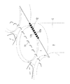
この際、図8(a)、(b)に示すように、段ボール箱Bが積上時に粗雑に扱われて、マルチパック包装体Mに局所的に非常に大きな衝撃が作用しても、図3に示すように、上記マルチパック包装体では、缶Cの保持にはあまり影響のない天板1と側板2の境界の中央部に入れられた弱め線12で切目12a間の繋部12bが破断することにより、衝撃が吸収されるので、缶Cの保持力が損なわれるような破れが生じにくい。
At this time, as shown in FIGS. 8A and 8B, even if the cardboard boxes B are roughly handled at the time of stacking and a very large impact is applied locally to the multipack package M, As shown in FIG. 3, in the said multipack package, the
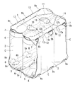
次に、この発明の第2実施形態を図4及び図5に基づいて説明する。なお、この第2実施形態は、上記第1実施形態と基本構成が共通することから、ここでは、共通部分に関する説明は省略し、相違点について言及するに留める。 Next, a second embodiment of the present invention will be described with reference to FIGS. Since the second embodiment has the same basic configuration as that of the first embodiment, the description regarding the common parts is omitted here, and only the differences are mentioned.
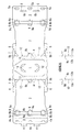
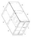
このマルチパック包装体は、図5に示すブランクから組み立てられるものであり、側板2と底板3の境界部分に、上記第1実施形態の抜穴9よりも大きい抜穴9aが形成され、側板2の天板1との境界部分には、抜穴9bが形成されている。天板1、両側の側板2及び底板3の連設方向の長さは、上記第1実施形態のものよりも少し短くなっている。
This multi-pack package is assembled from the blank shown in FIG. 5, and a
天板1と両側の側板2の境界部分には、中央の抜穴9bの付近から両端方向へかけて、その境界の罫線上に切目が断続するミシン目状の弱め線12が入れられている。弱め線12の抜穴9bの端部には、破れ止め用の切込9cが入れられており、同様の切込が側板2と天板1及び底板3の境界の罫線の他の端部にも入れられている。
At the boundary between the
そして、図4に示す缶Cの包装状態では、スリーブ状とされた天板1、両側の側板2及び底板3により缶Cが強く締め付けられ、抜穴9a,9bから缶Cの底部外周及び頂部外周がそれぞれ突き出すようになっている。
In the packaging state of the can C shown in FIG. 4, the can C is strongly tightened by the
このようなマルチパック包装体でも、流通過程において、段ボール箱に詰められた状態で粗雑に積み上げられ、局所的に非常に大きな衝撃が作用した場合、天板1と側板2の境界の中央部に入れられた弱め線12で切目12a間の繋部12bが破断することにより、衝撃が吸収されるので、抜穴9bの端部付近から開封用の切目線11へ至る破れのような缶Cの保持力が損なわれる破れが生じにくい。
Even in such a multi-pack package, in the distribution process, when it is roughly piled up in a state of being packed in a cardboard box and a very large impact is applied locally, a central portion of the boundary between the
なお、上記各実施形態において、天板1と側板2の境界の長さに対して、弱め線12の長さをあまり長く設定すると、単体での持ち運び時等における包装強度が低下するので、弱め線12の長さの比率は、1/5〜1/2程度としておくとよい。
In each of the above embodiments, if the length of the weakening
また、上記実施形態では、弱め線12として、切目12aが一定のピッチで断続するものを例示したが、切目12aのピッチが変化するものとしてもよい。
Moreover, in the said embodiment, although the
また、弱め線12が天板1と側板2の境界上に延びる直線のものを例示したが、弱め線12は、天板1と側板2の境界から少しずれた位置に入れられていてもよく、湾曲したものや、ジグザグに波打つ形状のものであってもよい。
Further, although the
1 天板
2 側板
3 底板
4 差込片
4a 係合片
5 差込穴
5a 係合穴
5b 押込片
6 折込片
7 抱持片
8 固定片
8a,8b 折目線
9,9a,9b 抜穴
9c 切込
10 指押片
11 切目線
12 弱め線
12a 切目
12b 繋部
B 段ボール箱
C 缶
M マルチパック包装体
DESCRIPTION OF
Claims (1)
集積された複数本の缶(C)が前記天板(1)と両側の側板(2)及び底板(3)により包囲され、両側の底板(3)が連結されてスリーブ状に保形され、
前記折込片(6)が内側へ折り込まれ、前記抱持片(7)が缶(C)の上部外周に沿って缶(C)の上部が保持され、前記固定片(8)が基部及び中間部の折目線(8a,8b)を軸として互いに逆方向へ折り曲げられ、固定片(8)の先端が缶(C)の底面の凹部周縁に係合して缶(C)の下部が保持され、これにより、両端面の開口部から缶(C)が抜け止めされるマルチパック包装体において、
前記天板(1)と側板(2)の境界の中央部又はその近傍に、両端面の開口部を結ぶ方向へ延びるように、かつ、いずれの端縁にも達しないように、切目(12a)と繋部(12b)が交互に断続するミシン目状の弱め線(12)が入れられていることを特徴とするマルチパック包装体。 The side plate (2) and the bottom plate (3) are sequentially connected to both sides of the top plate (1), and the folding pieces (6) are extended from both ends of the side plate (2) near the top plate (1). 6) and the corner of the top plate (1) are connected by a holding piece (7), and a fixed piece (8) is formed by cutting from the bottom plate (3) on both sides to the bottom of the side plate (2). The fold lines (8a, 8b) extending in the width direction are respectively inserted in the base portion and the intermediate portion of the fixed piece (8),
A plurality of accumulated cans (C) are surrounded by the top plate (1) and the side plates (2) and the bottom plate (3) on both sides, and the bottom plates (3) on both sides are connected and held in a sleeve shape,
The folding piece (6) is folded inward, the holding piece (7) is held at the upper part of the can (C) along the outer periphery of the upper part of the can (C), and the fixed piece (8) is the base and intermediate The fold line (8a, 8b) of the part is bent in opposite directions, and the tip of the fixed piece (8) is engaged with the peripheral edge of the recess on the bottom of the can (C) to hold the lower part of the can (C) In this way, in the multi-pack package in which the can (C) is prevented from coming off from the openings on both end faces,
A notch (12a) so as to extend in the direction connecting the openings of both end faces to the central part of the boundary between the top plate (1) and the side plate (2) or in the vicinity thereof and not reach any of the edges. ) And the connecting portion (12b) are alternately perforated with weak lines (12).
Priority Applications (1)
| Application Number | Priority Date | Filing Date | Title |
|---|---|---|---|
| JP2016084216A JP2017193347A (en) | 2016-04-20 | 2016-04-20 | Multipack package |
Applications Claiming Priority (1)
| Application Number | Priority Date | Filing Date | Title |
|---|---|---|---|
| JP2016084216A JP2017193347A (en) | 2016-04-20 | 2016-04-20 | Multipack package |
Publications (1)
| Publication Number | Publication Date |
|---|---|
| JP2017193347A true JP2017193347A (en) | 2017-10-26 |
Family
ID=60155478
Family Applications (1)
| Application Number | Title | Priority Date | Filing Date |
|---|---|---|---|
| JP2016084216A Pending JP2017193347A (en) | 2016-04-20 | 2016-04-20 | Multipack package |
Country Status (1)
| Country | Link |
|---|---|
| JP (1) | JP2017193347A (en) |
Cited By (2)
| Publication number | Priority date | Publication date | Assignee | Title |
|---|---|---|---|---|
| JP2021505487A (en) * | 2017-12-07 | 2021-02-18 | ウエストロック・パッケージング・システムズ・エルエルシー | Carton, and a blank for it |
| JP2021138378A (en) * | 2020-03-02 | 2021-09-16 | アサヒビール株式会社 | Multi-pack packaging material and can collective package |
-
2016
- 2016-04-20 JP JP2016084216A patent/JP2017193347A/en active Pending
Cited By (4)
| Publication number | Priority date | Publication date | Assignee | Title |
|---|---|---|---|---|
| JP2021505487A (en) * | 2017-12-07 | 2021-02-18 | ウエストロック・パッケージング・システムズ・エルエルシー | Carton, and a blank for it |
| JP7491841B2 (en) | 2017-12-07 | 2024-05-28 | ウエストロック・パッケージング・システムズ・エルエルシー | Cartons and blanks therefor |
| JP2021138378A (en) * | 2020-03-02 | 2021-09-16 | アサヒビール株式会社 | Multi-pack packaging material and can collective package |
| JP7389681B2 (en) | 2020-03-02 | 2023-11-30 | アサヒビール株式会社 | Multipack packaging materials and can assembly packaging |
Similar Documents
| Publication | Publication Date | Title |
|---|---|---|
| JP6890961B2 (en) | Blanks and cartons | |
| JP6334681B2 (en) | Carton & carton blank | |
| JP6704304B2 (en) | Packaging box | |
| JP6524141B2 (en) | Packaging box | |
| CN104507822A (en) | Carton and carton blank for forming a carton | |
| KR20160021189A (en) | Carton and carton blank | |
| KR20160022860A (en) | Carton and carton blank | |
| JP2018193069A5 (en) | ||
| JP3176309U (en) | Multipack | |
| JP3176824U (en) | Packaging box | |
| JP2017193347A (en) | Multipack package | |
| JP5315530B2 (en) | Multipack packaging box | |
| JP3202257U (en) | Packaging box | |
| JP6560583B2 (en) | Wrapping paper and packaging products | |
| JP2012192940A (en) | Packaging box | |
| JP7491841B2 (en) | Cartons and blanks therefor | |
| JP6167255B1 (en) | Box sheet | |
| JP7389681B2 (en) | Multipack packaging materials and can assembly packaging | |
| JP2018002294A (en) | Packing box | |
| JP3210395U (en) | Multi-pack package of small sealed container | |
| JP7848572B2 (en) | Trays, packaging, and tray usage instructions | |
| JP2018052541A (en) | Packing box for multipack | |
| TWI879815B (en) | Carton and blank therefor | |
| JP4629509B2 (en) | Multipack | |
| JP7484545B2 (en) | Packaging box |