JP2017194250A - Hot water supply apparatus and abnormality determination method thereof - Google Patents
Hot water supply apparatus and abnormality determination method thereof Download PDFInfo
- Publication number
- JP2017194250A JP2017194250A JP2016086329A JP2016086329A JP2017194250A JP 2017194250 A JP2017194250 A JP 2017194250A JP 2016086329 A JP2016086329 A JP 2016086329A JP 2016086329 A JP2016086329 A JP 2016086329A JP 2017194250 A JP2017194250 A JP 2017194250A
- Authority
- JP
- Japan
- Prior art keywords
- hot water
- pipe
- flow rate
- water supply
- flow
- Prior art date
- Legal status (The legal status is an assumption and is not a legal conclusion. Google has not performed a legal analysis and makes no representation as to the accuracy of the status listed.)
- Pending
Links
Images
Landscapes
- Heat-Pump Type And Storage Water Heaters (AREA)
Abstract
【課題】湯水の流れに異常が生じた場合にその異常を的確に捕えることができる信頼性にすぐれた給湯装置およびその異常判定方法を提供する。【解決手段】湯水を貯める貯湯タンク、この貯湯タンクの湯水を第1利用側機器へ供給する第1配管、前記貯湯タンクの湯水を第2利用側機器へ供給する第2配管、前記第1配管の湯水の流量を検知する流量検知手段を備え、前記第2配管に湯水が流れていないときの前記流量検知手段の検知流量と予め定めた基準流量との差に基づいて、前記第1利用側機器への湯水供給の異常を判定する。【選択図】図1A highly reliable hot water supply apparatus capable of accurately catching an abnormality when an abnormality occurs in the flow of hot water and a method for determining the abnormality are provided. A hot water storage tank for storing hot water, a first pipe for supplying hot water in the hot water storage tank to a first user side device, a second pipe for supplying hot water in the hot water storage tank to a second user side device, and the first pipe. and a flow rate detection means for detecting the flow rate of hot water in the second pipe, based on the difference between the flow rate detected by the flow rate detection means when no hot water is flowing in the second pipe and a predetermined reference flow rate, the first user side Judge the abnormality of the hot water supply to the equipment. [Selection drawing] Fig. 1
Description
本発明の実施形態は、貯湯タンクの湯水を浴槽に供給する給湯装置およびその異常判定方法に関する。 Embodiments described herein relate generally to a hot water supply apparatus that supplies hot water from a hot water storage tank to a bathtub and an abnormality determination method thereof.
ヒートポンプユニットの運転により貯湯タンクに湯水を貯え、貯えた湯水を配管により浴槽・浴室シャワー・台所・洗面所等に供給する給湯装置が知られている。 There is known a hot water supply device that stores hot water in a hot water storage tank by operating a heat pump unit, and supplies the stored hot water to a bathtub, a bathroom shower, a kitchen, a washroom, and the like by piping.
この給湯装置では、貯湯タンクの湯水を浴槽に供給する運転いわゆる“湯はり運転”時、貯湯タンクから浴槽へ流れる湯水の量を検出し、その検出量が設定量に達したところで運転を終了する。 This hot water supply device detects the amount of hot water flowing from the hot water storage tank to the bathtub during the operation of supplying hot water from the hot water storage tank to the bathtub, so-called “hot water operation”, and terminates the operation when the detected amount reaches the set amount. .
貯湯タンクと浴槽との間の配管の中に汚れやゴミが溜まった場合、あるいは浴槽の通湯口に存する循環金具のフィルタが目詰まりした場合、それが流路抵抗となって湯水が流れ難くなる。湯水が流れ難いと、“湯はり運転”に要する時間が長引いてしまう。配管内や循環金具のフィルタに溜まる汚れやゴミは徐々に増えるので、 “湯はり運転”の時間が長引いていることにユーザはなかなか気付かない。 If dirt or debris accumulates in the piping between the hot water storage tank and the bathtub, or if the filter of the circulation fitting at the hot water outlet of the bathtub is clogged, it becomes a flow path resistance, making it difficult for hot water to flow . If hot water is difficult to flow, the time required for “hot water operation” will be prolonged. Dirt and debris that accumulates in the piping and circulating metal filters gradually increase, so the user hardly notices that the “hot water operation” time is prolonged.
本発明の実施形態の目的は、湯水の流れに異常が生じた場合にその異常を的確に捕えることができる信頼性にすぐれた給湯装置およびその異常判定方法を提供することである。 An object of an embodiment of the present invention is to provide a reliable hot water supply apparatus and an abnormality determination method thereof capable of accurately capturing an abnormality when abnormality occurs in the flow of hot water.
請求項1の給湯装置は、湯水を貯める貯湯タンクと、この貯湯タンクの湯水を第1利用側機器へ供給する第1配管と、前記貯湯タンクの湯水を第2利用側機器へ供給する第2配管と、前記第1配管の湯水の流量を検知する流量検知手段と、判定手段とを備える。判定手段は、前記第2配管に湯水が流れていないときの前記流量検知手段の検知流量と予め定めた基準流量との差に基づいて、前記第1利用側機器への湯水供給の異常を判定する。
The hot water supply apparatus according to
請求項4の給湯装置の異常判定方法は、貯湯タンクの湯水を第1及び第2利用側機器へ供給する給湯装置の異常判定方法であって、前記第1利用側機器への湯水の流量を検知する流量検知ステップと、前記第2利用側機器に湯水が供給されていないときの前記流量検知ステップの検知流量に基づいて、前記第1利用側機器への湯水供給の異常を判定する判定ステップと、を備える。
An abnormality determination method for a hot water supply apparatus according to
以下、一実施形態について図面を参照して説明する。
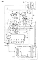
図1に示すように、屋外に設置される給湯ユニット(貯湯タンクユニットともいう)1に、外部の給水源から供給される水が給水管A1を通って流入する。流入した水は、配管2およびその配管2上の減圧弁3および逆止弁4を通って貯湯タンク5の底部流入口に流れる。この減圧弁3と逆止弁4との間に流れる水の一部が逆止弁6を介して混合弁7の第1流入口に導かれ、その混合弁7から流出する湯水が配管(第2配管)8および給湯管(第2配管)A2を通って第2利用側機器たとえば浴室シャワー・台所蛇口・洗面所蛇口等に供給される。配管8には、湯水の流れの有無を検知する流れセンサ(流れ検知手段)9が取付けられている。混合弁7の第2流入口は、配管10を介して貯湯タンク5の上部流出口に接続されている。
Hereinafter, an embodiment will be described with reference to the drawings.
As shown in FIG. 1, water supplied from an external water supply source flows into a hot water supply unit (also referred to as a hot water storage tank unit) 1 installed outdoors through a water supply pipe A1. The inflowing water flows to the bottom inlet of the hot
配管10の中途部に逆止弁11が配置され、その配管10における逆止弁11より上流側の湯が混合弁12の第1流入口に導かれる。この混合弁12の第2流入口には、上記配管2における減圧弁3と逆止弁4との間の水が導かれる。そして、混合弁12で混合された湯水が配管(第1配管)14およびその配管14上のホッパ15、銀イオン発生器20、フロースイッチ21を介して屋外の配管(第1配管)A3に供給される。配管A3は、建屋の中に導入されて浴室60内の第1利用側機器たとえば浴槽61の通湯口に接続されている。この通湯口には、ゴミ除去用のフィルタを内蔵した循環金具62が取付けられている。ホッパ15は、開閉弁16、逆止弁17、流量センサ(流量検知手段)18、および逆止弁19を有する。流量センサ18は、当該ホッパ15を通って流れる湯水の単位時間t当たりの流量(リットル/t)を検知する。
A
混合弁12の流出口とホッパ15との間の配管14に、混合弁12で混合された湯水の温度を検知する湯温センサ51が取付けられている。また、配管14におけるフロースイッチ21の配設位置の近傍に、内部の湯水の温度を検知する水温センサ22、および配管14,A3を通して浴槽61内の湯水の水位を検知する水位センサ23が取付けられている。フロースイッチ21は、配管A3,14内を通る湯水の流量が一定以上か否かを検知する検知手段として機能するもので、一定以上の場合にオンして一定未満の場合はオフする。
A hot water temperature sensor 51 for detecting the temperature of hot water mixed by the mixing valve 12 is attached to the pipe 14 between the outlet of the mixing valve 12 and the
配管14の銀イオン発生器20を経た湯水の一部は、ふろポンプ24および配管25を通って加温用の熱交換器26の第1流路に供給され、その第1流路を経た湯水が配管27により屋外の配管A4に供給される。配管A4も、建屋の中に導入されて浴槽61の循環金具62に接続されている。配管27には、配管A4に向かって流れる湯の温度を検知する湯温センサ28が取付けられている。
Part of the hot water that has passed through the silver ion generator 20 of the pipe 14 is supplied to the first flow path of the heat exchanger 26 for heating through the bath pump 24 and the pipe 25, and the hot water that has passed through the first flow path. Is supplied to the outdoor pipe A4 by the
上記配管10における逆止弁11より上流側の湯が配管30およびその配管30上の逆止弁31を介して上記熱交換器26の第2流路に導かれ、その第2流路を経た湯が配管32、追炊きポンプ33、および配管44により貯湯タンク5の上部流入口に供給される。
Hot water on the upstream side of the
貯湯タンク5の底部流出口から流出する湯水が配管40および循環ポンプ41により外部の配管A5に供給される。配管A5は加熱手段であるヒートポンプユニット70の入水口に接続されている。そして、配管40における循環ポンプ41より上流側位置が三方弁42の第1流出口に接続され、その三方弁42の流入口が配管43により外部の配管A6に接続されている。配管A6は、ヒートポンプユニット70の流出口に接続されている。三方弁42は、配管43から流入する湯を第1流出口および第2流出口のいずれか一方または両方から流出させる。第2流出口から流出する湯は上記配管44により貯湯タンク5の上部流入口に導かれる。配管43に入水温度センサ45が取付けられ、配管44に沸上げ温度センサ46が取付けられる。入水温度センサ45は、配管A6から給湯ユニット1に流入する湯水の温度を検知する、沸上げ温度センサ46は、配管44から貯湯タンク5の上部流入口に流れる湯の温度を検知する。
Hot water flowing out from the bottom outlet of the hot
貯湯タンク5内の湯水の温度および水位は、その貯湯タンク5の下部から上部にかけて順に配置された複数の温度センサT1,T2,…T6により検知される。
The temperature and water level of the hot water in the hot
貯湯タンク5内には加熱手段であるヒートポンプ70で沸き上げられた高温の温湯が配管44を介して上部から貯留されていくため、上方から下方に向かって温度分布を有する湯水が貯留される。すなわち、高温の温湯は上方に貯留され、冷温の湯水が下方に貯留される。
In the hot
上記ヒートポンプユニット70は、圧縮機71、水-冷媒熱交換器72の冷媒側流路、内部熱交換器73の第1流路、減圧器たとえば膨張弁74、空気熱交換器75、および内部熱交換器73の第2流路を順次に接続して冷媒を循環させるヒートポンプ式冷凍サイクルを有するとともに、空気熱交換器75に外気を送るファン76、上記配管A5から流入する湯水を水-冷媒熱交換器72の水側流路に導く配管77、水-冷媒熱交換器72の水側流路から流出する湯を上記配管A6に導く配管78、配管77内の湯水の温度を検知する給水温度センサ81、および配管78内の湯水の温度を検知する沸上げ温度センサ82を有し、給湯ユニット1から供給される水を外気から汲み上げた熱で加熱し、その加熱により得られる湯を給湯ユニット1へ供給する。
The heat pump unit 70 includes a compressor 71, a refrigerant-side flow path of the water-refrigerant heat exchanger 72, a first flow path of the internal heat exchanger 73, a decompressor such as an
給湯ユニット1にコントローラ50が設けられ、そのコントローラ50に給湯ユニット1内の弁・ポンプ・温度センサ、外気温度センサ83、浴室60のリモートコントロール式操作器(操作手段;リモコンと略称する)63、およびヒートポンプユニット70が接続されている。リモコン63は、液晶表示部、音声入出力部、操作扉などを前面に有する。
A
コントローラ50は、当該給水装置の全体を制御するもので、主要な機能として制御手段50a〜50d、判定手段50e、報知手段50fを有する。
制御手段50aは、貯湯タンク5内の湯水をヒートポンプユニット70によって加熱しながら貯湯タンク5に貯える“貯湯運転”の実行を制御する。
The
The control means 50 a controls execution of “hot water storage operation” in which hot water in the hot
制御手段50bは、貯湯タンク5内の湯を配管A3,A4を通して浴槽61に供給する“湯はり運転”の実行を制御する。
The control means 50b controls execution of “hot water operation” in which hot water in the hot
制御手段50cは、ふろポンプ24の運転により、浴槽61内の湯水を配管A3,A4および熱交換器26に通して循環させる保温用・追い炊き用の“循環運転”の実行を制御する。
The control means 50 c controls the execution of the “circulation operation” for heat insulation and cooking for circulating the hot water in the bathtub 61 through the
制御手段50dは、リモコン63の洗浄ボタンスイッチが押圧操作された場合、貯湯タンク5内の湯水が配管10,14と配管A3を通って浴槽61に流れ、かつ配管14における銀イオン発生器20を経た湯水の一部がふろポンプ24、配管25、熱交換器26、配管27、配管A4を通って浴槽61に流れる洗浄用流路を一定時間だけ形成し、その形成時に銀イオン発生器20を動作させる“洗浄運転”の実行を制御する。
When the washing button switch of the remote controller 63 is pressed, the control means 50d causes the hot water in the hot
判定手段50eは、当該給湯装置が設置された後で上記“湯はり運転”が最初に実行された場合、配管8および給湯管A2における湯水の流れが流れセンサ9で検知されていないときの流量センサ18の検知流量(リットル/t)Waを基準流量として内部メモリに記憶し、その後の2回目以降の“湯はり運転”において、配管8および給湯管A2における湯水の流れが流れセンサ9で検知されていないときの流量センサ18の検知流量Wbと上記記憶した基準流量Waとの差ΔW(=Wa−Wb)を求め、その差ΔWが所定値ΔWs以上の場合に、浴槽61への給湯が異常であると判定する。
The determination means 50e is a flow rate when the flow of hot water in the pipe 8 and the hot water supply pipe A2 is not detected by the
報知手段50fは、判定手段50eが給湯の異常を判定した場合に、その旨をリモコン63の文字や画像の表示あるいはブザー音発生により報知する。 When the determination unit 50e determines that the hot water supply is abnormal, the notification unit 50f notifies the fact by displaying characters or images on the remote controller 63 or generating a buzzer sound.
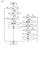
つぎに、コントローラ50が実行する制御を図2のフローチャートを参照しながら説明する。
“湯はり運転”の実行に際し(ステップS1のYES)、コントローラ50は、この運転が当該給湯装置が設置された後の最初の初回運転(試運転ともいう)であるか否かを判定する(ステップS2)。初回運転である場合(ステップS2のYES)、コントローラ50は、混合弁7,配管8,給湯管A2を通る第2利用側機器(浴室シャワー・台所蛇口・洗面所蛇口等)への湯水の流れが流れセンサ9で検知されていないことを条件に(ステップS3のYES)、貯湯タンク5から配管10,混合弁12,配管14,ホッパ15,配管A3を通って浴槽61へと流れる湯水の流量(リットル/t)Waをホッパ15の流量センサ18で検知する(ステップS4)。そして、コントローラ50は、流量センサ18の検知流量Waを配管や弁に汚れやゴミが溜まっていない初期状態の基準流量として内部メモリに記憶する(ステップS5)。
Next, the control executed by the
When executing the “hot water operation” (YES in step S1), the
2回目以降の“湯はり運転”の実行に際し(ステップS1のYES,ステップS2のNO)、コントローラ50は、混合弁7,配管8,給湯管A2を通る第2利用側機器(浴室シャワー・台所蛇口・洗面所蛇口等)への湯水の流れが流れセンサ9で検知されていないことを条件に(ステップS6のYES)、貯湯タンク5から配管10,混合弁12,配管14,ホッパ15,配管A3を通って浴槽61へと流れる湯水の流量Wbをホッパ15の流量センサ18で検知する(ステップS7)。そして、コントローラ50は、流量センサ18の検知流量Wbと上記記憶した基準流量Waとの差ΔW(=Wa−Wb)を求め(ステップS8)、求めた差ΔWが予め定めた所定値ΔWs以上であるか否かを判定する(ステップS9)。所定値ΔWsは、例えば、基準流量Waの1/2の値である。
When performing the second and subsequent “hot water operation” (YES in step S1, NO in step S2), the
差ΔWが所定値ΔWs以上の場合(ステップS9のYES)、コントローラ50は、浴槽61への給湯に異常があると判定し(ステップS10)、その判定結果をリモコン63によって報知する(ステップS11)。
When the difference ΔW is equal to or larger than the predetermined value ΔWs (YES in step S9), the
浴槽61への給湯経路である配管10,混合弁12,配管14,ホッパ15,配管A3のいずれかに汚れやゴミが溜まっている場合、あるいは循環金具62のフィルタが目詰まりしている場合、それらが流路抵抗となって湯水が流れ難くなる。湯水が流れ難くなると流量センサ18の検知流量Wdが減少するので、それを浴槽61への給湯異常として捕らえてリモコン63により報知するようにしている。
When dirt or dust collects in any of the
“湯はり運転”を行っている最中に第2利用側機器である浴室シャワー・台所・洗面所等へ給湯が行われた場合、その給湯分だけ浴槽61へ流れる湯水の量が少なくなるので、的確な異常判定が不可能となる。そこで、第2利用側機器への湯水の流れがあるかどうかを流れセンサ9により検知し、流れがないことを条件に異常判定を行うようにしている。これにより、浴槽61への給湯の異常を的確に捕えることができ、給湯装置としての信頼性が大幅に向上する。ユーザは、浴槽61への給湯に異常があることをリモコン63の報知により察知し、直ちに異常の解消を保守管理者に委託することができる。
If hot water is supplied to the bathroom shower / kitchen / washroom, etc., which is the second user side device during the “hot water operation”, the amount of hot water flowing into the bathtub 61 is reduced by that amount. Therefore, accurate abnormality determination is impossible. Therefore, the
貯湯タンク5と配管10との接続部あるいは配管10と混合弁12との接続部から湯水が漏れる不具合が生じた場合も、流量センサ18の検知流量Wdが減少するので、それを浴槽61への給湯の異常として捕らえて報知することができる。
Even when there is a problem that hot water leaks from the connecting portion between the hot
上記実施形態では、所定値ΔWsが基準流量Waの1/2の値である場合を例に説明したが、その値については配管の長さや太さなどに応じて適宜に選定可能である。 In the above embodiment, the case where the predetermined value ΔWs is ½ of the reference flow rate Wa has been described as an example. However, the value can be appropriately selected according to the length and thickness of the pipe.
また、上記実施形態では、初回運転時の場合に基準流量の検知と記憶を行ったが、基準流量が内部メモリに記憶されていない場合に、初回運転とみなして、基準流量を記憶してもよい。また、リモコン操作により基準流量を記憶させてもよい。 In the above embodiment, the reference flow rate is detected and stored in the case of the first operation. However, if the reference flow rate is not stored in the internal memory, the reference flow rate is stored as the first operation. Good. Further, the reference flow rate may be stored by remote control operation.
その他、上記実施形態および変形例は、例として提示したものであり、発明の範囲を限定することは意図していない。この新規な各実施形態および変形例は、その他の様々な形態で実施されることが可能であり、発明の要旨を逸脱しない範囲で、種々の省略、書き換え、変更を行うことができる。これら実施形態や変形は、発明の範囲は要旨に含まれるとともに、特許請求の範囲に記載された発明とその均等の範囲に含まれる。 In addition, the said embodiment and modification are shown as an example and are not intending limiting the range of invention. Each of the novel embodiments and modifications can be implemented in various other forms, and various omissions, rewrites, and changes can be made without departing from the spirit of the invention. In these embodiments and modifications, the scope of the invention is included in the gist, and is included in the invention described in the claims and the equivalents thereof.
1…給湯ユニット、5…貯湯タンク、12…混合弁、14…配管(第1配管)、15…ホッパ、16…開閉弁、18…流量センサ、20…銀イオン発生器、21…フロースイッチ(検知手段)、23…水位センサ、A2…給湯管(第2配管)、A3…配管(第1配管)、24…ふろポンプ、25…配管、26…熱交換器、27…配管、A4…配管、50…コントローラ、60…浴室、61…浴槽(第1利用側機器)、63…リモコン
DESCRIPTION OF
Claims (4)
前記貯湯タンクの湯水を第1利用側機器へ供給する第1配管と、
前記貯湯タンクの湯水を第2利用側機器へ供給する第2配管と、
前記第1配管の湯水の流量を検知する流量検知手段と、
前記第2配管に湯水が流れていないときの前記流量検知手段の検知流量と予め定めた基準流量との差に基づいて、前記第1利用側機器への湯水供給の異常を判定する判定手段と、
を備えることを特徴とする給湯装置。 A hot water storage tank for storing hot water,
A first pipe for supplying hot water from the hot water storage tank to a first user side device;
A second pipe for supplying hot water from the hot water storage tank to a second use side device;
Flow rate detection means for detecting the flow rate of hot water in the first pipe;
Determining means for determining an abnormality in hot water supply to the first usage-side device based on a difference between a detected flow rate of the flow rate detecting means when no hot water is flowing in the second pipe and a predetermined reference flow rate; ,
A hot water supply apparatus comprising:
をさらに備えたことを特徴とする請求項1に記載の給湯装置。 Flow detection means for detecting the flow of hot water in the second pipe;
The hot water supply apparatus according to claim 1, further comprising:
ことを特徴とする請求項2に記載の給湯装置。 The determination means is a flow rate detected by the flow rate detection means when hot water supply to the first user side device is first executed after the hot water supply apparatus is installed and no flow of hot water is detected by the flow detection means. Is stored as the reference flow rate, and then the detected flow rate of the flow rate detection means and the reference flow rate when hot water supply to the first user side device is executed and no flow of hot water is detected by the flow detection means, When the difference is equal to or greater than a predetermined value, it is determined that the hot water supply to the first user side device is abnormal.
The hot-water supply apparatus of Claim 2 characterized by the above-mentioned.
前記第1利用側機器への湯水の流量を検知する流量検知ステップと、
前記第2利用側機器に湯水が供給されていないときの前記流量検知ステップの検知流量に基づいて、前記第1利用側機器への湯水供給の異常を判定する判定ステップと、
を備えたことを特徴とする給湯装置の異常判定方法。 An abnormality determination method for a hot water supply device that supplies hot water in a hot water storage tank to first and second usage-side devices,
A flow rate detecting step for detecting a flow rate of hot water to the first usage side device;
A determination step of determining an abnormality in hot water supply to the first usage-side device based on a detected flow rate of the flow rate detection step when hot water is not supplied to the second usage-side device;
An abnormality determination method for a hot water supply apparatus, comprising:
Priority Applications (1)
| Application Number | Priority Date | Filing Date | Title |
|---|---|---|---|
| JP2016086329A JP2017194250A (en) | 2016-04-22 | 2016-04-22 | Hot water supply apparatus and abnormality determination method thereof |
Applications Claiming Priority (1)
| Application Number | Priority Date | Filing Date | Title |
|---|---|---|---|
| JP2016086329A JP2017194250A (en) | 2016-04-22 | 2016-04-22 | Hot water supply apparatus and abnormality determination method thereof |
Publications (1)
| Publication Number | Publication Date |
|---|---|
| JP2017194250A true JP2017194250A (en) | 2017-10-26 |
Family
ID=60155406
Family Applications (1)
| Application Number | Title | Priority Date | Filing Date |
|---|---|---|---|
| JP2016086329A Pending JP2017194250A (en) | 2016-04-22 | 2016-04-22 | Hot water supply apparatus and abnormality determination method thereof |
Country Status (1)
| Country | Link |
|---|---|
| JP (1) | JP2017194250A (en) |
Citations (3)
| Publication number | Priority date | Publication date | Assignee | Title |
|---|---|---|---|---|
| JP2009250478A (en) * | 2008-04-03 | 2009-10-29 | Panasonic Corp | Storage water heater |
| JP2012032031A (en) * | 2010-07-29 | 2012-02-16 | Corona Corp | Hot water storage type water heater |
| JP2012063081A (en) * | 2010-09-16 | 2012-03-29 | Corona Corp | Hot water supply device |
-
2016
- 2016-04-22 JP JP2016086329A patent/JP2017194250A/en active Pending
Patent Citations (3)
| Publication number | Priority date | Publication date | Assignee | Title |
|---|---|---|---|---|
| JP2009250478A (en) * | 2008-04-03 | 2009-10-29 | Panasonic Corp | Storage water heater |
| JP2012032031A (en) * | 2010-07-29 | 2012-02-16 | Corona Corp | Hot water storage type water heater |
| JP2012063081A (en) * | 2010-09-16 | 2012-03-29 | Corona Corp | Hot water supply device |
Similar Documents
| Publication | Publication Date | Title |
|---|---|---|
| JP6337425B2 (en) | Bathtub cleaning equipment | |
| JP2013245919A5 (en) | ||
| CN108592411A (en) | Hot-water heating system and hot water control method | |
| JP5866226B2 (en) | Water heater | |
| US10801751B2 (en) | Water consuming appliance and a method for operating the same | |
| JP5133773B2 (en) | Water heater | |
| JP5956830B2 (en) | Water heater | |
| JP2011191039A (en) | Hot water storage type water heater system | |
| JP2013015284A (en) | Storage type water heater | |
| JP6545081B2 (en) | Hot water heater | |
| JP6623881B2 (en) | Hot water supply system | |
| JP6102781B2 (en) | Hot water storage water heater | |
| JP2019184116A (en) | Water heater | |
| JP2015052422A (en) | Abnormality notification method in water heater and water heater | |
| JP2011163693A (en) | Water heater with bath automatic function | |
| JP4264081B2 (en) | Hot water storage water heater | |
| CN108354556A (en) | Wash the control method and washing electric appliance of electric appliance | |
| JP2009109105A (en) | Hot water supply device | |
| JP2013096683A (en) | Hot water storage type water heater | |
| JP2014070858A (en) | Water heater | |
| JP5865129B2 (en) | Water heater | |
| JP5248433B2 (en) | Hot water storage bath water heater | |
| JP2010270924A (en) | Hot water supply apparatus and hot water supply method | |
| JP5687841B2 (en) | Mist sauna equipment | |
| KR20180077741A (en) | Dishwasher |
Legal Events
| Date | Code | Title | Description |
|---|---|---|---|
| A621 | Written request for application examination |
Free format text: JAPANESE INTERMEDIATE CODE: A621 Effective date: 20190403 |
|
| A131 | Notification of reasons for refusal |
Free format text: JAPANESE INTERMEDIATE CODE: A131 Effective date: 20200121 |
|
| A977 | Report on retrieval |
Free format text: JAPANESE INTERMEDIATE CODE: A971007 Effective date: 20200117 |
|
| A02 | Decision of refusal |
Free format text: JAPANESE INTERMEDIATE CODE: A02 Effective date: 20200804 |