JP2017196692A - Cutting tool - Google Patents
Cutting tool Download PDFInfo
- Publication number
- JP2017196692A JP2017196692A JP2016088957A JP2016088957A JP2017196692A JP 2017196692 A JP2017196692 A JP 2017196692A JP 2016088957 A JP2016088957 A JP 2016088957A JP 2016088957 A JP2016088957 A JP 2016088957A JP 2017196692 A JP2017196692 A JP 2017196692A
- Authority
- JP
- Japan
- Prior art keywords
- cutting
- cutting tool
- cutting edge
- tool
- rotationally symmetric
- Prior art date
- Legal status (The legal status is an assumption and is not a legal conclusion. Google has not performed a legal analysis and makes no representation as to the accuracy of the status listed.)
- Granted
Links
Images


Classifications
-
- B—PERFORMING OPERATIONS; TRANSPORTING
- B23—MACHINE TOOLS; METAL-WORKING NOT OTHERWISE PROVIDED FOR
- B23B—TURNING; BORING
- B23B27/00—Tools for turning or boring machines; Tools of a similar kind in general; Accessories therefor
- B23B27/14—Cutting tools of which the bits or tips or cutting inserts are of special material
- B23B27/16—Cutting tools of which the bits or tips or cutting inserts are of special material with exchangeable cutting bits or cutting inserts, e.g. able to be clamped
- B23B27/1603—Cutting tools of which the bits or tips or cutting inserts are of special material with exchangeable cutting bits or cutting inserts, e.g. able to be clamped with specially shaped plate-like exchangeable cutting inserts, e.g. chip-breaking groove
- B23B27/1611—Cutting tools of which the bits or tips or cutting inserts are of special material with exchangeable cutting bits or cutting inserts, e.g. able to be clamped with specially shaped plate-like exchangeable cutting inserts, e.g. chip-breaking groove characterised by having a special shape
-
- B—PERFORMING OPERATIONS; TRANSPORTING
- B23—MACHINE TOOLS; METAL-WORKING NOT OTHERWISE PROVIDED FOR
- B23B—TURNING; BORING
- B23B1/00—Methods for turning or working essentially requiring the use of turning-machines; Use of auxiliary equipment in connection with such methods
-
- B—PERFORMING OPERATIONS; TRANSPORTING
- B23—MACHINE TOOLS; METAL-WORKING NOT OTHERWISE PROVIDED FOR
- B23B—TURNING; BORING
- B23B27/00—Tools for turning or boring machines; Tools of a similar kind in general; Accessories therefor
- B23B27/14—Cutting tools of which the bits or tips or cutting inserts are of special material
- B23B27/141—Specially shaped plate-like cutting inserts, i.e. length greater or equal to width, width greater than or equal to thickness
- B23B27/145—Specially shaped plate-like cutting inserts, i.e. length greater or equal to width, width greater than or equal to thickness characterised by having a special shape
-
- B—PERFORMING OPERATIONS; TRANSPORTING
- B23—MACHINE TOOLS; METAL-WORKING NOT OTHERWISE PROVIDED FOR
- B23B—TURNING; BORING
- B23B2200/00—Details of cutting inserts
- B23B2200/04—Overall shape
- B23B2200/0485—Trapezium
-
- B—PERFORMING OPERATIONS; TRANSPORTING
- B23—MACHINE TOOLS; METAL-WORKING NOT OTHERWISE PROVIDED FOR
- B23B—TURNING; BORING
- B23B2200/00—Details of cutting inserts
- B23B2200/08—Rake or top surfaces
-
- B—PERFORMING OPERATIONS; TRANSPORTING
- B23—MACHINE TOOLS; METAL-WORKING NOT OTHERWISE PROVIDED FOR
- B23B—TURNING; BORING
- B23B2200/00—Details of cutting inserts
- B23B2200/20—Top or side views of the cutting edge
-
- B—PERFORMING OPERATIONS; TRANSPORTING
- B23—MACHINE TOOLS; METAL-WORKING NOT OTHERWISE PROVIDED FOR
- B23B—TURNING; BORING
- B23B2200/00—Details of cutting inserts
- B23B2200/20—Top or side views of the cutting edge
- B23B2200/202—Top or side views of the cutting edge with curved cutting edge
-
- B—PERFORMING OPERATIONS; TRANSPORTING
- B23—MACHINE TOOLS; METAL-WORKING NOT OTHERWISE PROVIDED FOR
- B23B—TURNING; BORING
- B23B2200/00—Details of cutting inserts
- B23B2200/24—Cross section of the cutting edge
- B23B2200/242—Cross section of the cutting edge bevelled or chamfered
-
- B—PERFORMING OPERATIONS; TRANSPORTING
- B23—MACHINE TOOLS; METAL-WORKING NOT OTHERWISE PROVIDED FOR
- B23B—TURNING; BORING
- B23B2200/00—Details of cutting inserts
- B23B2200/24—Cross section of the cutting edge
- B23B2200/245—Cross section of the cutting edge rounded
-
- B—PERFORMING OPERATIONS; TRANSPORTING
- B23—MACHINE TOOLS; METAL-WORKING NOT OTHERWISE PROVIDED FOR
- B23B—TURNING; BORING
- B23B2200/00—Details of cutting inserts
- B23B2200/28—Angles
-
- B—PERFORMING OPERATIONS; TRANSPORTING
- B23—MACHINE TOOLS; METAL-WORKING NOT OTHERWISE PROVIDED FOR
- B23B—TURNING; BORING
- B23B2200/00—Details of cutting inserts
- B23B2200/36—Other features of cutting inserts not covered by B23B2200/04 - B23B2200/32
- B23B2200/3609—Chamfers
-
- B—PERFORMING OPERATIONS; TRANSPORTING
- B23—MACHINE TOOLS; METAL-WORKING NOT OTHERWISE PROVIDED FOR
- B23B—TURNING; BORING
- B23B2200/00—Details of cutting inserts
- B23B2200/36—Other features of cutting inserts not covered by B23B2200/04 - B23B2200/32
- B23B2200/3645—Lands, i.e. the outer peripheral section of the rake face
- B23B2200/3663—Lands, i.e. the outer peripheral section of the rake face having negative cutting angles
-
- B—PERFORMING OPERATIONS; TRANSPORTING
- B23—MACHINE TOOLS; METAL-WORKING NOT OTHERWISE PROVIDED FOR
- B23B—TURNING; BORING
- B23B2200/00—Details of cutting inserts
- B23B2200/36—Other features of cutting inserts not covered by B23B2200/04 - B23B2200/32
- B23B2200/369—Mounted tangentially, i.e. where the rake face is not the face with the largest area
-
- B—PERFORMING OPERATIONS; TRANSPORTING
- B23—MACHINE TOOLS; METAL-WORKING NOT OTHERWISE PROVIDED FOR
- B23B—TURNING; BORING
- B23B2224/00—Materials of tools or workpieces composed of a compound including a metal
- B23B2224/04—Aluminium oxide
-
- B—PERFORMING OPERATIONS; TRANSPORTING
- B23—MACHINE TOOLS; METAL-WORKING NOT OTHERWISE PROVIDED FOR
- B23B—TURNING; BORING
- B23B2226/00—Materials of tools or workpieces not comprising a metal
- B23B2226/12—Boron nitride
- B23B2226/125—Boron nitride cubic [CBN]
Landscapes
- Engineering & Computer Science (AREA)
- Mechanical Engineering (AREA)
- Cutting Tools, Boring Holders, And Turrets (AREA)
- Turning (AREA)
Abstract
【課題】回転している工作物の回転対称面の切削加工に好適な切削工具を提供する。【解決手段】本発明の一態様に係る切削工具10は、回転している工作物の回転対称面の切削加工のための切削工具である。切削加工は、回転対称面に切削工具10を接触させながら、回転対称面の回転軸線に対して傾斜した方向に切削工具10を送る工程を含む。切削工具10を送る工程において、切削工具10の回転対称面に接触する点が、切削工具が送られるにつれて移動する。切削工具は、すくい面1と、逃げ面2と、すくい面1と逃げ面2とをつなぐ切れ刃3とを備える。逃げ面2から見た切れ刃3の形状は、少なくとも1つの円弧を含み、円弧の曲率半径は、100mm以上500mm以下である。【選択図】図1A cutting tool suitable for cutting a rotationally symmetric surface of a rotating workpiece is provided. A cutting tool 10 according to an aspect of the present invention is a cutting tool for cutting a rotationally symmetric surface of a rotating workpiece. Cutting includes a step of feeding the cutting tool 10 in a direction inclined with respect to the rotational axis of the rotationally symmetric surface while bringing the cutting tool 10 into contact with the rotationally symmetric surface. In the process of sending the cutting tool 10, the point that contacts the rotationally symmetric surface of the cutting tool 10 moves as the cutting tool is sent. The cutting tool includes a rake face 1, a flank face 2, and a cutting edge 3 that connects the rake face 1 and the flank face 2. The shape of the cutting edge 3 viewed from the flank 2 includes at least one arc, and the radius of curvature of the arc is not less than 100 mm and not more than 500 mm. [Selection] Figure 1
Description
本発明は、切削工具に関する。 The present invention relates to a cutting tool.
国際公開第2001/043902号(特許文献1)は、工作物の加工方法を開示する。この方法によれば、切れ刃は、送り方向に対して傾斜して配置されて、回転している工作物の回転軸線を横断する方向に送られる。この加工方法により、工作物の表面が滑らかとなるように工作物の表面を加工できるとともに、高能率での加工が可能になる。 International Publication No. 2001/043902 (Patent Document 1) discloses a machining method for a workpiece. According to this method, the cutting edge is arranged to be inclined with respect to the feeding direction and is fed in a direction crossing the rotation axis of the rotating workpiece. By this processing method, the surface of the workpiece can be processed so that the surface of the workpiece becomes smooth, and processing with high efficiency becomes possible.
国際公開第2001/043902号は、上記の切削加工にとって好適な切削工具を具体的に開示していない。 International Publication No. 2001/043902 does not specifically disclose a cutting tool suitable for the above cutting.
本発明の目的は、回転している工作物の回転対称面の切削加工に好適な切削工具を提供することである。 An object of the present invention is to provide a cutting tool suitable for cutting a rotationally symmetric surface of a rotating workpiece.
本発明の一態様に係る切削工具は、回転している工作物の回転対称面の切削加工のための切削工具である。切削加工は、回転対称面に切削工具を接触させながら、回転対称面の回転軸線に対して傾斜した方向に切削工具を送る工程を含む。切削工具を送る工程において、切削工具の回転対称面に接触する点が、切削工具が送られるにつれて移動する。切削工具は、すくい面と、逃げ面と、すくい面と逃げ面とをつなぐ切れ刃とを備える。逃げ面から見た切れ刃の形状は、少なくとも1つの円弧を含み、円弧の曲率半径は、100mm以上500mm以下である。 A cutting tool according to an aspect of the present invention is a cutting tool for cutting a rotationally symmetric surface of a rotating workpiece. The cutting process includes a step of sending the cutting tool in a direction inclined with respect to the rotation axis of the rotationally symmetric surface while bringing the cutting tool into contact with the rotationally symmetric surface. In the process of sending the cutting tool, the point that contacts the rotationally symmetric surface of the cutting tool moves as the cutting tool is sent. The cutting tool includes a rake face, a flank face, and a cutting edge that connects the rake face and the flank face. The shape of the cutting edge viewed from the flank includes at least one arc, and the radius of curvature of the arc is not less than 100 mm and not more than 500 mm.
上記によれば、回転している工作物の回転対称面の切削加工に好適な切削工具を提供することができる。 According to the above, it is possible to provide a cutting tool suitable for cutting a rotationally symmetric surface of a rotating workpiece.
[本発明の実施形態の説明]
最初に本発明の実施態様を列記して説明する。
[Description of Embodiment of the Present Invention]
First, embodiments of the present invention will be listed and described.
(1) 本発明の一態様に係る切削工具は、回転している工作物の回転対称面の切削加工のための切削工具である。切削加工は、回転対称面に切削工具を接触させながら、回転対称面の回転軸線に対して傾斜した方向に切削工具を送る工程を含む。切削工具を送る工程において、切削工具の回転対称面に接触する点が、切削工具が送られるにつれて移動する。切削工具は、すくい面と、逃げ面と、すくい面と逃げ面とをつなぐ切れ刃とを備える。逃げ面から見た切れ刃の形状は、少なくとも1つの円弧を含み、円弧の曲率半径は、100mm以上500mm以下である。 (1) A cutting tool according to an aspect of the present invention is a cutting tool for cutting a rotationally symmetric surface of a rotating workpiece. The cutting process includes a step of sending the cutting tool in a direction inclined with respect to the rotation axis of the rotationally symmetric surface while bringing the cutting tool into contact with the rotationally symmetric surface. In the process of sending the cutting tool, the point that contacts the rotationally symmetric surface of the cutting tool moves as the cutting tool is sent. The cutting tool includes a rake face, a flank face, and a cutting edge that connects the rake face and the flank face. The shape of the cutting edge viewed from the flank includes at least one arc, and the radius of curvature of the arc is not less than 100 mm and not more than 500 mm.
上記によれば、回転している工作物の回転対称面の切削加工に好適な切削工具を提供することができる。切削工具を送る工程において、切削工具の回転対称面に接触する点が、切削工具が送られるにつれて移動する。すなわち切れ刃の全体が回転対称面の切削加工に用いられる。これにより、回転対称面の面粗さを小さくすることができる。逃げ面から見た切れ刃の形状が円弧を含むことによって、切削抵抗を小さくすることができる。一方で、その円弧の曲率半径が、100mm以上500mm以下であるので、逃げ面の摩耗量を少なくすることができる。したがって、切削工具の寿命を長くすることができる。 According to the above, it is possible to provide a cutting tool suitable for cutting a rotationally symmetric surface of a rotating workpiece. In the process of sending the cutting tool, the point that contacts the rotationally symmetric surface of the cutting tool moves as the cutting tool is sent. That is, the entire cutting edge is used for cutting a rotationally symmetric surface. Thereby, the surface roughness of the rotationally symmetric surface can be reduced. When the shape of the cutting edge viewed from the flank includes an arc, cutting resistance can be reduced. On the other hand, since the radius of curvature of the arc is 100 mm or more and 500 mm or less, the wear amount of the flank can be reduced. Therefore, the life of the cutting tool can be extended.
(2) 好ましくは、(1)に記載の切削工具において、切れ刃の長さは、12mm以上50mm以下である。 (2) Preferably, in the cutting tool according to (1), the length of the cutting edge is 12 mm or more and 50 mm or less.
上記によれば、切れ刃の全体を使用した回転対称面の切削加工が可能になる。したがって、逃げ面の摩耗量を少なくすることができる。これにより、切削工具の寿命を長くすることができる。切れ刃が短い場合には、回転対称面に接触する切削工具の点の位置は、切削加工の間、ほとんど変化しない。このような切削(ポイント切削)の場合、逃げ面の摩耗量が大きくなりやすい。一方で、切れ刃が長い場合には、切削加工の間に、切削工具の回転対称面に接触する切削工具の点の位置を切れ刃に沿って移動させることができる。しかし、切れ刃における未使用の部分が生じやすい。したがって上記構成によれば、切れ刃を効率よく使用することができる。 According to the above, it becomes possible to cut a rotationally symmetric surface using the entire cutting edge. Therefore, the wear amount of the flank can be reduced. Thereby, the lifetime of a cutting tool can be lengthened. If the cutting edge is short, the position of the point of the cutting tool that contacts the rotationally symmetric surface will hardly change during the cutting process. In such cutting (point cutting), the amount of wear on the flank tends to increase. On the other hand, when the cutting edge is long, the position of the point of the cutting tool that contacts the rotationally symmetric surface of the cutting tool can be moved along the cutting edge during the cutting process. However, an unused part in the cutting edge tends to occur. Therefore, according to the said structure, a cutting edge can be used efficiently.
(3) 好ましくは、(1)または(2)に記載の切削工具において、すくい面と逃げ面とがなす切削工具のくさび角は、65°以上90°以下である。 (3) Preferably, in the cutting tool according to (1) or (2), the wedge angle of the cutting tool formed by the rake face and the flank face is 65 ° or more and 90 ° or less.
上記によれば、切削抵抗を小さくすることができる。硬度の高い材質からなる工作物の切削加工の場合には、工作物に切れ刃を食い込ませるために、切れ刃にには、より大きな力が印加される。くさび角が上記の範囲内にあることにより、切れ刃が損傷する(たとえば切れ刃の一部に欠損が生じる)可能性をより小さくすることができる。 According to the above, cutting resistance can be reduced. In the case of cutting a workpiece made of a material having high hardness, a larger force is applied to the cutting edge in order to bite the cutting edge into the workpiece. When the wedge angle is within the above range, the possibility that the cutting edge is damaged (for example, a defect occurs in a part of the cutting edge) can be further reduced.
(4) 好ましくは、(1)から(3)のいずれかに記載の切削工具において、切れ刃は、立方晶窒化硼素を含む焼結体の一部である。 (4) Preferably, in the cutting tool according to any one of (1) to (3), the cutting edge is a part of a sintered body containing cubic boron nitride.
上記によれば、安定加工に充分な硬度を有する材料によって切れ刃が形成される。したがって硬度の高い材料からなる工作物の切削加工が可能になるとともに、切削工具の寿命を長くすることができる。 According to the above, the cutting edge is formed of the material having sufficient hardness for stable processing. Therefore, it is possible to cut a workpiece made of a material having high hardness, and to prolong the life of the cutting tool.
(5) 好ましくは、(1)から(4)のいずれかに記載の切削工具において、逃げ面から見たときに、切れ刃は、すくい面と反対側の背面に向かう先細り形状を有する。 (5) Preferably, in the cutting tool according to any one of (1) to (4), when viewed from the flank face, the cutting edge has a tapered shape toward the back surface opposite to the rake face.
上記によれば、切れ刃の側方にも逃げ角が形成される。これにより、回転対称面の切削加工時に、切れ刃の一方の端部から切れ刃の他方の端部までの切れ刃全体を使用することができる。 According to the above, a clearance angle is also formed on the side of the cutting edge. Thereby, the whole cutting edge from one edge part of a cutting edge to the other edge part of a cutting edge can be used at the time of the cutting process of a rotationally symmetric surface.
(6) 好ましくは、(1)から(5)のいずれかに記載の切削工具において、切れ刃は、第1の端部と、第1の端部の反対側にある第2の端部とを含む。第1の端部および第2の端部の各々は、切れ刃の曲率半径よりも小さい曲率半径を有する。 (6) Preferably, in the cutting tool according to any one of (1) to (5), the cutting edge includes a first end and a second end on the opposite side of the first end. including. Each of the first end and the second end has a radius of curvature that is smaller than the radius of curvature of the cutting edge.
上記によれば、回転対称面の切削加工時に、切れ刃の第1の端部または切れ刃の第2の端部において欠損が生じる可能性を低減することができる。 According to the above, when cutting the rotationally symmetric surface, it is possible to reduce the possibility that a defect occurs at the first end portion of the cutting edge or the second end portion of the cutting edge.
(7) 好ましくは、(1)から(6)のいずれかに記載の切削工具において、切れ刃は、丸み付けられたホーニング部を有する。すくい面を基準としたホーニング部のホーニング量は、0.001mm以上0.030mm以下である。 (7) Preferably, in the cutting tool according to any one of (1) to (6), the cutting edge has a rounded honing portion. The honing amount of the honing portion with respect to the rake face is 0.001 mm or more and 0.030 mm or less.
上記によれば、切削抵抗が大きくなるのを抑えながら、切れ刃の強度を保持することができる。 According to the above, the strength of the cutting edge can be maintained while suppressing an increase in cutting resistance.
(8) 好ましくは、(1)から(7)のいずれかに記載の切削工具において、切れ刃は、ネガランド部を有する。逃げ面に対してネガランド部がなす角度は、0°以上35°以下である。 (8) Preferably, in the cutting tool according to any one of (1) to (7), the cutting edge has a negative land portion. The angle formed by the negative land portion with respect to the flank is 0 ° or more and 35 ° or less.
上記によれば、切削抵抗が大きくなるのを抑えることができる。
[本発明の実施形態の詳細]
以下、図面に基づいて本発明の実施の形態を説明する。以下の図面において同一または相当する部分には同一の参照番号を付し、その説明は繰返さない。なお、説明を分かりやすくするために、図面において、発明の構成要素の一部のみが示される場合がある。
According to the above, it is possible to suppress an increase in cutting resistance.
[Details of the embodiment of the present invention]
Hereinafter, embodiments of the present invention will be described with reference to the drawings. In the following drawings, the same or corresponding parts are denoted by the same reference numerals, and description thereof will not be repeated. For ease of explanation, only some of the components of the invention may be shown in the drawings.
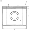
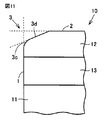
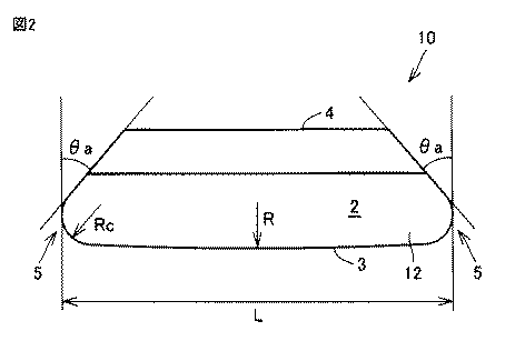
図1は、本発明の実施の形態に係る切削工具の斜視図である。図2は、本発明の実施の形態に係る切削工具の上面図である。図3は、本発明の実施の形態に係る切削工具の正面図である。図4は、本発明の実施の形態に係る切削工具の右側面図である。 FIG. 1 is a perspective view of a cutting tool according to an embodiment of the present invention. FIG. 2 is a top view of the cutting tool according to the embodiment of the present invention. FIG. 3 is a front view of the cutting tool according to the embodiment of the present invention. FIG. 4 is a right side view of the cutting tool according to the embodiment of the present invention.
図1〜図4を参照して、本発明の実施形態に係る切削工具10は、すくい面1と、逃げ面2と、切れ刃3とを有する。
1 to 4, a
切れ刃3は、すくい面1と、逃げ面2とが交差する部分に対応する。言い換えると、切れ刃3は、すくい面1と、逃げ面2とが繋がることによって形成された部分に対応する。
The
切れ刃3は、すくい面1と、逃げ面2とをつなぐ稜線であってもよい。このような切れ刃を「シャープエッジ」と呼ぶことができる。あるいは、切れ刃3の加工によって、ホーニング部、あるいは、ネガランド部、または、ホーニング部とネガランド部との組合わせ、からなる群より選択される1以上の部位が、すくい面1と逃げ面2とを繋ぐ面(すなわち切れ刃3)に形成されてもよい。ホーニング部およびネガランド部の具体例は後述する。
The
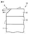
切削工具10は、基材11と、硬質焼結体12と、接合部材13とを含む。基材11は、すくい面1の少なくとも一部、および、逃げ面2の少なくとも一部を含む。さらに、基材11は、すくい面1の反対側に位置する背面4を含む。
The cutting
硬質焼結体12は、立方晶窒化硼素(以下「cBN」とも記す)を含む焼結体である。安定加工に充分な硬度を有する材料によって切れ刃が形成される。したがって硬度の高い材料からなる工作物の切削加工が可能になるとともに、切削工具の寿命を長くすることができる。硬質焼結体12は、たとえばcBNと、Al2O3およびZr化合物等とを含んだ焼結体であってもよい。硬質焼結体12によって、切れ刃3、すくい面1の少なくとも一部、および、逃げ面2の少なくとも一部が形成される。接合部材13は、硬質焼結体12を基材11に接合する部材である。
The
図2に典型的に示されるように、逃げ面2から見た場合の切れ刃3の形状は円弧である。円弧の曲率半径Rは、100mm以上500mm以下である。一実施形態では、曲率半径Rは、150mmである。
As typically shown in FIG. 2, the shape of the
図2〜図4に示された1つの実施の形態では、逃げ面2から見た場合の切れ刃3の形状は単数の円弧である。しかしながら切れ刃3は、複数の円弧を組み合わせた形状を有してもよい。
In one embodiment shown in FIGS. 2 to 4, the shape of the
切れ刃3は、長さLを有する。一実施形態では、長さLは、12mm以上50mm以下である。一実施形態では、長さLは15〜20mmの範囲内にある。
The
切れ刃3は、第1の端部、および、第1の端部と反対側の第2の端部に、コーナー部5を有する。コーナー部5には丸みがつけられる。コーナー部5の曲率半径Rcは、切れ刃3の曲率半径Rよりも小さい(Rc<R)。これにより、切れ刃3は、その側方に逃げ角θaを有する。言い換えると、逃げ面2から見た切れ刃の形状は、すくい面2から背面4に向かう先細りの形状である。一実施形態では、逃げ角θaは、41°である。
The
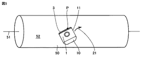
図5は、本発明の実施の形態に係る切削工具を用いた切削加工を示した概略図である。図5を参照して、被削材50は、回転軸線51を中心として回転する。切削工具10は、図示しないホルダに取付けられて、被削材50の回転対称面52に押し付けられる。切削工具10は、軌道21に沿って、回転対称面52上を移動する。これにより、切れ刃3が回転対称面52を加工する。
FIG. 5 is a schematic view showing cutting using the cutting tool according to the embodiment of the present invention. Referring to FIG. 5, the
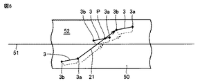
図6は、図5に示された切削加工の模式的に示した模式図である。図5および図6を参照して、切削開始時には、切れ刃3は、一方の端部3aの位置において回転対称面52に接触する。切削工具10を送ることにより、回転対称面52に接触する切れ刃3の位置(点P)は、切れ刃3に沿って端部3aから移動する。切削終了時には、切れ刃3の点Pは、切れ刃3の他方の端部3bに位置する。
FIG. 6 is a schematic diagram schematically showing the cutting process shown in FIG. Referring to FIGS. 5 and 6, at the start of cutting, cutting
端部3aから端部3bまでの切れ刃3の個々の領域が、加工されるべき面(回転対称面52)に順次接触する。この加工方法により、被削物50の表面が滑らかとなるように被削物50の表面を加工できるとともに、高能率での加工が可能になる。さらに、切れ刃の全体を使用するため、逃げ面の摩耗量を少なくすることができる。したがって切削工具の寿命を長くすることができる。
The individual regions of the
上記の加工方法では、切れ刃3の接触抵抗と被削物50の加工後の表面粗さとが相互に関係する。切れ刃3の形状が直線に近いほど、被削物50の加工後の表面粗さは小さい。一方で、被削物50に接触する接触抵抗が大きくなる。本発明の実施の形態では、切れ刃3の曲率半径は、100mm以上500mm以下の範囲内にある。これにより、切れ刃3の接触抵抗が大きくなるのを抑えながら、被削物50の表面を滑らかに加工することができる。
In the above processing method, the contact resistance of the
さらに、上記の加工方法では、切れ刃3の全体を使用して被削物50の表面が切削される。切れ刃3が短い場合、実質的には、切れ刃3の同じ領域を用いて被削物50の表面が切削される。この場合には、面粗さが大きくなる可能性がある。一例では、回転対称面52に、ねじ状の溝が形成される。さらに、逃げ面の摩耗量が大きくなりやすい。一方、切れ刃3が長すぎる場合、被削物50の大きさによっては、切削に関与しない切れ刃3の領域が生じる。したがって切れ刃3の全体を有効に利用できない。
Further, in the above processing method, the entire surface of the
本発明の実施の形態では、切れ刃3の長さは12mm以上50mm以下の範囲内である。したがって切れ刃3の全体を有効に使用した切削加工を実現することができる。
In the embodiment of the present invention, the length of the
図7は、被削物の切削加工時における切れ刃の部分拡大図である。図7を参照して、くさび角θbは、すくい面1と、逃げ面2との間のなす角度である。くさび角θbが小さいほど、刃先抵抗は小さい。
FIG. 7 is a partially enlarged view of the cutting edge during cutting of the work. Referring to FIG. 7, wedge angle θb is an angle formed between
たとえば被削物50が焼入れ鋼のように硬度の高い材質からなる場合、切れ刃3を被削物50に食い込ませるために、切削工具10を、方向22に沿って強く押し付けなければならない。くさび角θbが小さい場合には、切れ刃の欠損が生じやすい。本発明の実施の形態では、くさび角θは65°以上90°以下の範囲内にある。これにより、切削抵抗を小さくしながら、切れ刃の欠損が生じる可能性を小さくすることができる。
For example, when the
図8は、切れ刃3の側方の逃げ角θaによる効果を説明するための模式図である。図8に示されるように、切削開始時には、切れ刃3の端部3a(コーナー部5)が被削物50の表面に接する。切れ刃3の逃げ角θaによって、切れ刃3の端部3aによる加工が可能となる。同様に、切削終了の直前には、切れ刃3の端部3bによって、被削物50の表面が切削される。逃げ角θaにより、切れ刃3の全体を使用した切削加工が可能である。
FIG. 8 is a schematic diagram for explaining the effect of the side clearance angle θa of the
さらに、切れ刃3は、コーナー部5を有する。コーナー部5の曲率半径は、切れ刃3の曲率半径よりも小さい(図2を参照)。これにより、切れ刃3の欠けを抑制することができる。あるいは、被削物50の加工後の表面の面粗さを小さくすることができる。
Further, the
切れ刃3の形状は、シャープエッジ形状に限定されるものではない。具体的には、切れ刃3には面取り加工が施されてもよい。以下に、切れ刃3の処理の例を示す。
The shape of the
図9は、切れ刃3の処理の第1の例を示した模式図である。図9に示されるように、切れ刃3には、ホーニング加工が施されてもよい。すなわち、切れ刃3はは、丸みが付けられた部分(ホーニング部3c)を有する。Hは、すくい面1を基準としたホーニング部3cのホーニング量である。この実施の形態では、ホーニング量Hは、0.001mm以上0.030mm以下である。
FIG. 9 is a schematic diagram showing a first example of processing of the
図10は、切れ刃3の処理の第2の例を示した模式図である。図10に示されるように、切れ刃3には、ネガランド加工が施されてもよい。すなわち、切れ刃3はネガランド部3dを有する。ネガランド角度θnは、逃げ面2に対してネガランド部3dがなす角度である。この実施の形態では、ネガランド角度θnは、0°以上35°以下である。
FIG. 10 is a schematic diagram illustrating a second example of the processing of the
図11は、切れ刃3の処理の第3の例を示した模式図である。図11に示されるように、切れ刃3には、ホーニング加工に加えてネガランド加工が施されてもよい。すなわち切れ刃3はホーニング部3cとネガランド部3dとを有してもよい。
FIG. 11 is a schematic diagram showing a third example of the processing of the
[切削試験1]
切れ刃の曲率半径が切削性能に及ぼす影響を調べた。以下の表1に記載した実施例および比較例の切削工具について、以下の切削条件に従って切削加工を行ない、仕上げ面粗さ、切削抵抗、および工具摩耗を評価した。その評価結果を表1に示す。この評価では、仕上げ面粗さRz(十点平均粗さ)が3.0μm以下であり、切削抵抗が250N以下であり、かつ、逃げ面の摩耗量については欠損が発生しなかった切削工具を良好と判断した。
[Cutting test 1]
The effect of the radius of curvature of the cutting edge on the cutting performance was investigated. The cutting tools of Examples and Comparative Examples described in Table 1 below were cut according to the following cutting conditions, and the finished surface roughness, cutting resistance, and tool wear were evaluated. The evaluation results are shown in Table 1. In this evaluation, a cutting tool having a finished surface roughness Rz (ten-point average roughness) of 3.0 μm or less, a cutting resistance of 250 N or less, and no flank wear was generated. Judged to be good.
(切削条件)
被削材:傾斜角11°を有する回転対称面、焼入れ鋼(SCM415H)、HRC60
切削方法:回転対称斜面の切削
切削形態:乾式切削
切削速度:300m/min
工具の切り込み深さ:0.1mm
工具の送り速さ:0.3mm/rev
(工具形状)
工具材質:平均粒径が約4μmのcBN粒子を70体積%含有する多結晶硬質焼結体
切れ刃形状:表1参照
刃先形状:Rホーニング(ホーニング量0.010mm)
切れ刃長さ:15.875mm
工具逃げ角:0°
ホルダ取り付け時の逃げ角:15°
(Cutting conditions)
Work material: rotationally symmetric surface with an inclination angle of 11 °, hardened steel (SCM415H), HRC60
Cutting method: Cutting of rotationally symmetric slope Cutting form: Dry cutting Cutting speed: 300 m / min
Tool cutting depth: 0.1 mm
Tool feed rate: 0.3 mm / rev
(Tool shape)
Tool material: polycrystalline hard sintered body containing 70% by volume of cBN particles having an average particle diameter of about 4 μm Cutting edge shape: See Table 1 Cutting edge shape: R honing (honing amount 0.010 mm)
Cutting edge length: 15.875 mm
Tool clearance angle: 0 °
Clearance angle when attaching holder: 15 °
試料番号1Aの切削工具では、切削抵抗は小さかった。しかし仕上げ面粗さに関して、仕上げ面粗さRzが3μmを上回った。一方、試料番号1F,1Gの切削工具では、仕上げ面粗さRzは3μm以下であった。しかし切削抵抗が300N以上であった。試料番号1Gの切削工具では、切れ刃に欠損が発生した。 In the cutting tool of sample number 1A, the cutting resistance was small. However, regarding the finished surface roughness, the finished surface roughness Rz exceeded 3 μm. On the other hand, in the cutting tools of sample numbers 1F and 1G, the finished surface roughness Rz was 3 μm or less. However, the cutting resistance was 300N or more. In the cutting tool of sample number 1G, the cutting edge was damaged.
試料番号1B〜1Eの各々の切削工具については、仕上げ面粗さ、切削抵抗ともに良好であった。さらに、切れ刃には欠損が生じなかった。 About each cutting tool of sample number 1B-1E, finishing surface roughness and cutting resistance were favorable. In addition, the cutting edge was not damaged.
上述の結果は、切れ刃の形状が円弧であることによって切削抵抗を低減することができることを示す。しかし切れ刃の曲率半径Rが小さすぎる場合には、仕上げ面が粗くなる。表1に示されるように、切れ刃の曲率半径は、100mm以上500mm以下であることが好ましいことが確認された。 The above-mentioned result shows that cutting resistance can be reduced by the shape of the cutting edge being an arc. However, when the curvature radius R of the cutting edge is too small, the finished surface becomes rough. As shown in Table 1, it was confirmed that the curvature radius of the cutting edge is preferably 100 mm or more and 500 mm or less.
[切削試験2]
切れ刃の長さが切削加工時における切削抵抗と工具摩耗とに与える影響を調べた。以下の表2に記載した実施例および比較例の切削工具について、以下の切削条件に従って切削加工を行ない、切削抵抗を評価した。その評価結果を表2に示す。この評価では、切削抵抗が300N以下であり、逃げ面の摩耗量が30μm以下である切削工具を良好と判断した。
[Cutting test 2]
The effect of cutting edge length on cutting resistance and tool wear during cutting was investigated. The cutting tools of Examples and Comparative Examples described in Table 2 below were cut according to the following cutting conditions, and the cutting resistance was evaluated. The evaluation results are shown in Table 2. In this evaluation, a cutting tool having a cutting resistance of 300 N or less and a flank wear amount of 30 μm or less was judged to be good.
(切削条件)
被削材:傾斜角11°を有する回転対称面、焼入れ鋼(S052)、HRC60
切削方法:回転対称斜面の切削
切削形態:湿式切削
切削速度:400m/min
工具の切り込み深さ:0.05mm
工具の送り速さ:0.4mm/rev
(工具形状)
工具材質:平均粒径が約2μmのcBN粒子を50体積%含有する多結晶硬質焼結体
切れ刃形状:円弧形状(切れ刃半径150mm)
刃先形状:Rホーニング(ホーニング量0.010mm)
切れ刃長さ:表2を参照
工具逃げ角:0°
ホルダ取り付け時の逃げ角:15°
(Cutting conditions)
Work material: rotationally symmetric surface with an inclination angle of 11 °, hardened steel (S052), HRC60
Cutting method: Cutting of rotationally symmetric slope Cutting form: Wet cutting Cutting speed: 400 m / min
Cutting depth of tool: 0.05mm
Tool feed rate: 0.4mm / rev
(Tool shape)
Tool material: Polycrystalline hard sintered body containing 50% by volume of cBN particles having an average particle diameter of about 2 μm Cutting edge shape: Arc shape (cutting edge radius 150 mm)
Cutting edge shape: R Honing (Honing amount 0.010mm)
Cutting edge length: See Table 2 Tool clearance angle: 0 °
Clearance angle when attaching holder: 15 °
試料番号2A,2Bの各々の切削工具では、切削抵抗は低かった。しかし試料番号2Aの切削工具では、逃げ面の摩耗量が50μm以上であった。試料番号2Bの切削工具では、逃げ面の摩耗量が30μm以上であった。 In each of the cutting tools of sample numbers 2A and 2B, the cutting resistance was low. However, in the cutting tool of sample number 2A, the amount of wear on the flank face was 50 μm or more. In the cutting tool of sample number 2B, the wear amount of the flank was 30 μm or more.
試料番号2Hの切削工具に関し、試料番号2A,2Bの切削工具に比べて、逃げ面の摩耗量が小さかった。しかし、切削抵抗に関して、300Nを超える抵抗が発生した。試料番号2C〜2Gの各々の切削工具に関しては、切削抵抗、逃げ面の摩耗量はともに良好であった。 Regarding the cutting tool of sample number 2H, the amount of wear on the flank was small compared to the cutting tools of sample numbers 2A and 2B. However, regarding the cutting resistance, a resistance exceeding 300 N was generated. Regarding each of the cutting tools of sample numbers 2C to 2G, both the cutting resistance and the wear amount of the flank were good.
上述の結果は、切れ刃の長さが50mm以下の切削工具では小さい切削抵抗が得られることを示す。さらに、上述の結果は、切れ刃の長さが10mm以上の切削工具では、切れ刃の長さが3mmあるいは5mmの切削工具に比べて、逃げ面の摩耗量が小さいことを示す。 The above-mentioned results show that a small cutting resistance can be obtained with a cutting tool having a cutting edge length of 50 mm or less. Furthermore, the above-described results show that the amount of wear on the flank is smaller in a cutting tool having a cutting edge length of 10 mm or more than in a cutting tool having a cutting edge length of 3 mm or 5 mm.
逃げ面の摩耗量が小さいほど、切削工具の寿命が長くなっていることを示す。表2に示されるように、切れ刃の長さに関しては10mm以上50mm以下の長さが好ましいことが確認された。 The smaller the amount of wear on the flank, the longer the tool life. As shown in Table 2, it was confirmed that the length of the cutting edge was preferably 10 mm or more and 50 mm or less.
[切削試験3]
くさび角が切削性能に与える影響を調べた。以下の表3に記載した実施例および比較例の切削工具について、以下の切削条件に従って切削加工を行い、切削抵抗と欠損の有無について評価した。この評価では、切削抵抗が300N以下であり、かつ欠損が発生しなかった切削工具を良好と判断した。
(切削条件)
被削材:円柱状の焼入れ鋼 (SCV420H)、HRC60
切削方法:回転対称面の切削
切削形態:湿式切削
切削速度:220m/min
工具の切り込み深さ:0.15mm
工具の送り速さ:0.2mm/rev
(工具形状)
工具材質:平均粒径が約3μmのcBN粒子を65体積%含有する多結晶硬質焼結体
切れ刃形状:円弧形状(切れ刃半径150mm)
刃先形状:表5を参照
切れ刃長さ:15.875mm
工具くさび角:表3を参照
ホルダ取り付け時の工具逃げ角:15°
[Cutting test 3]
The effect of wedge angle on cutting performance was investigated. About the cutting tool of the Example and comparative example which were described in the following Table 3, it cut according to the following cutting conditions, and evaluated the cutting resistance and the presence or absence of a defect | deletion. In this evaluation, a cutting tool having a cutting resistance of 300 N or less and having no chipping was determined to be good.
(Cutting conditions)
Work material: Cylindrical hardened steel (SCV420H), HRC60
Cutting method: Cutting of rotationally symmetric surface Cutting form: Wet cutting Cutting speed: 220 m / min
Cutting depth of tool: 0.15mm
Tool feed rate: 0.2mm / rev
(Tool shape)
Tool material: Polycrystalline hard sintered body containing 65% by volume of cBN particles having an average particle diameter of about 3 μm Cutting edge shape: Arc shape (cutting edge radius 150 mm)
Cutting edge shape: See Table 5 Cutting edge length: 15.875 mm
Tool wedge angle: See Table 3 Tool clearance angle when the holder is attached: 15 °
試料番号3Gの切削工具では、切削抵抗が最も小さい一方で、欠損が発生した。試料番号3A〜3Fの各々の切削工具では、切削抵抗は300N以下であり、かつ欠損の発生が抑制された。 In the cutting tool of sample number 3G, the cutting resistance was the smallest, but a defect occurred. In each of the cutting tools of sample numbers 3A to 3F, the cutting resistance was 300 N or less, and the occurrence of defects was suppressed.
上述の結果から、切削工具のくさび角が65°以上90°以下の範囲内であることが、良好な切削性能を得る上で好ましいことが確認された。 From the above results, it was confirmed that the wedge angle of the cutting tool is preferably in the range of 65 ° or more and 90 ° or less in order to obtain good cutting performance.
[切削試験4]
切削工具のホーニング量が切削加工時における切削抵抗に及ぼす影響を調べた。以下の表4に記載した実施例および比較例の切削工具について、以下の切削条件に従って切削加工を行い、切削抵抗と耐欠損性について評価した。この評価では切削抵抗が250N以下であり、かつ、欠損が発生しない切削工具を良好と判断した。
(切削条件)
被削材:傾斜角9°を有する回転対称面、焼入れ鋼(SCM415H)、HRC60
切削方法:回転対称斜面の切削
切削形態:乾式切削
切削速度:300m/min
工具の切り込み深さ:0.1mm
工具の送り速さ:0.3mm/rev
(工具形状)
工具材質:平均粒径が約4μmのcBN粒子を70体積%含有する多結晶硬質焼結体
切れ刃形状:円弧形状(切れ刃半径150mm)
刃先形状:表4を参照
切れ刃長さ:15.875mm
工具逃げ角:0°
ホルダ取り付け時の逃げ角:15°
[Cutting test 4]
The effect of the honing amount of the cutting tool on the cutting force during cutting was investigated. About the cutting tool of the Example and comparative example which were described in the following Table 4, it cut according to the following cutting conditions, and evaluated cutting resistance and fracture resistance. In this evaluation, it was determined that a cutting tool having a cutting resistance of 250 N or less and having no chipping was good.
(Cutting conditions)
Work material: rotationally symmetric surface with an inclination angle of 9 °, hardened steel (SCM415H), HRC60
Cutting method: Cutting of rotationally symmetric slope Cutting form: Dry cutting Cutting speed: 300 m / min
Tool cutting depth: 0.1 mm
Tool feed rate: 0.3 mm / rev
(Tool shape)
Tool material: Polycrystalline hard sintered body containing 70% by volume of cBN particles having an average particle diameter of about 4 μm Cutting edge shape: Arc shape (cutting edge radius 150 mm)
Cutting edge shape: See Table 4 Cutting edge length: 15.875 mm
Tool clearance angle: 0 °
Clearance angle when attaching holder: 15 °
試料番号4Aの切削工具は、刃先にホーニング処理が施されていない切削工具、すなわち、シャープエッジを有する切削工具であった。試料番号4Aの切削工具は、他の試料番号の切削工具に比べて小さな切削抵抗を有するものの、欠損が発生した。一方、試料番号4Gの切削工具では、欠損が発生しなかったものの、切削抵抗が250N以上であった。試料番号4B〜4Fの各々の切削工具については、切削抵抗および耐欠損性がともに良好であった。 The cutting tool of Sample No. 4A was a cutting tool whose blade edge was not honed, that is, a cutting tool having a sharp edge. Although the cutting tool of sample number 4A had a smaller cutting resistance than the cutting tools of other sample numbers, defects occurred. On the other hand, in the cutting tool of sample number 4G, no chipping occurred, but the cutting resistance was 250 N or more. About each cutting tool of sample number 4B-4F, both cutting resistance and fracture resistance were favorable.
上述の結果から、切削抵抗の低減と優れた耐欠損性とを両立できるホーニング量は0.001mm以上0.030mm以下の範囲内であることが確認できた。 From the above results, it was confirmed that the amount of honing that can achieve both reduction in cutting resistance and excellent fracture resistance is in the range of 0.001 mm to 0.030 mm.
[切削試験5]
切削工具のネガランド角度が切削加工時における切削抵抗に与える影響について調べた。以下の表5に記載した実施例および比較例の切削工具について、以下の切削条件に従って切削加工を行い、切削抵抗を評価した。この評価では切削抵抗が350N以下である切削工具を良好と判断した。
(切削条件)
被削材:円柱状の焼入れ鋼 (SCM415H)、HRC60
切削方法:回転対称面の切削
切削形態:乾式切削
切削速度:220m/min
工具の切り込み深さ:0.15mm
工具の送り速さ:0.2mm/rev
(工具形状)
工具材質:平均粒径が約4μmのcBN粒子を70体積%含有する多結晶硬質焼結対
切れ刃形状:円弧形状(切れ刃半径200mm)
刃先形状:表5を参照
切れ刃長さ:15.875mm
工具逃げ角:0°
ホルダ取り付け時の逃げ角15°
[Cutting test 5]
The effect of the negative land angle of the cutting tool on the cutting force during cutting was investigated. About the cutting tool of the Example and comparative example which were described in the following Table 5, cutting was performed according to the following cutting conditions, and cutting resistance was evaluated. In this evaluation, a cutting tool having a cutting resistance of 350 N or less was judged good.
(Cutting conditions)
Work material: Columnar quenched steel (SCM415H), HRC60
Cutting method: Cutting of rotationally symmetric surface Cutting form: Dry cutting Cutting speed: 220 m / min
Cutting depth of tool: 0.15mm
Tool feed rate: 0.2mm / rev
(Tool shape)
Tool material: polycrystalline hard sintered containing 70% by volume of cBN particles having an average particle diameter of about 4 μm vs. cutting edge shape: arc shape (cutting edge radius 200 mm)
Cutting edge shape: See Table 5 Cutting edge length: 15.875 mm
Tool clearance angle: 0 °
Clearance angle 15 ° when attaching holder
試料番号5Eの切削工具では、370Nを超える切削抵抗が発生した。一方、試料番号5A〜5Eの各々の切削工具では、ネガランド角度が35°以下であった。試料番号5A〜5Eの切削工具の間では、ネガランド角度が大きいほど切削抵抗が大きかった。しかし、試料番号5A〜5Eのいずれの切削工具においても、切削抵抗は350N未満であった。 In the cutting tool of sample number 5E, cutting resistance exceeding 370 N was generated. On the other hand, in each cutting tool of sample numbers 5A to 5E, the negative land angle was 35 ° or less. Among the cutting tools of sample numbers 5A to 5E, the larger the negative land angle, the greater the cutting resistance. However, in any of the cutting tools of sample numbers 5A to 5E, the cutting resistance was less than 350N.
上記の結果から、ネガランドの角度が0°以上35以下であることが、切削抵抗を抑制できる点で好ましいことが確認された。 From the above results, it was confirmed that the angle of the negative land is preferably 0 ° or more and 35 or less in that the cutting resistance can be suppressed.
今回開示された実施の形態はすべての点で例示であって、制限的なものではないと考えられるべきである。本発明の範囲は上記した実施の形態ではなく特許請求の範囲によって示され、特許請求の範囲と均等の意味、および範囲内でのすべての変更が含まれることが意図される。 The embodiment disclosed this time is to be considered as illustrative in all points and not restrictive. The scope of the present invention is shown not by the above-described embodiment but by the scope of claims, and is intended to include meanings equivalent to the scope of claims and all modifications within the scope.
1 すくい面
2 逃げ面
3 切れ刃
3a,3b 端部(切れ刃)
3c ホーニング部
3d ネガランド部
4 背面
5 コーナー部
10 切削工具
11 基材
12 硬質焼結体
13 接合部材
21 軌道
22 方向
50 被削材
51 回転軸線
52 回転対称面
H ホーニング量
L 長さ
P 点
R,Rc 曲率半径
1
Claims (8)
前記切削工具を送る工程において、前記切削工具の前記回転対称面に接触する点が、前記切削工具が送られるにつれて移動し、
前記切削工具は、
すくい面と、
逃げ面と、
前記すくい面と前記逃げ面とをつなぐ切れ刃とを備え、
前記逃げ面から見た前記切れ刃の形状は、少なくとも1つの円弧を含み、
前記円弧の曲率半径は、100mm以上500mm以下である、切削工具。 A cutting tool for cutting a rotationally symmetric surface of a rotating workpiece, wherein the cutting is performed with respect to the rotational axis of the rotationally symmetric surface while bringing the cutting tool into contact with the rotationally symmetric surface. Sending the cutting tool in an inclined direction;
In the step of sending the cutting tool, the point of contact with the rotationally symmetric surface of the cutting tool moves as the cutting tool is sent,
The cutting tool is
Rake face,
Flank and
A cutting edge connecting the rake face and the flank face;
The shape of the cutting edge viewed from the flank includes at least one arc;
A cutting tool having a radius of curvature of the arc of 100 mm to 500 mm.
第1の端部と、
前記第1の端部の反対側にある第2の端部とを含み、
前記第1の端部および前記第2の端部の各々は、前記切れ刃の前記曲率半径よりも小さい曲率半径を有する、請求項1から請求項5のいずれか1項に記載の切削工具。 The cutting edge is
A first end;
A second end opposite to the first end,
The cutting tool according to any one of claims 1 to 5, wherein each of the first end and the second end has a radius of curvature smaller than the radius of curvature of the cutting edge.
前記すくい面を基準とした前記ホーニング部のホーニング量は、0.001mm以上0.030mm以下である、請求項1から請求項6のいずれか1項に記載の切削工具。 The cutting edge has a rounded honing portion;
The cutting tool according to any one of claims 1 to 6, wherein a honing amount of the honing portion with respect to the rake face is 0.001 mm or more and 0.030 mm or less.
前記逃げ面に対して前記ネガランド部がなす角度は、0°以上35°以下である、請求項1から請求項7のいずれか1項に記載の切削工具。 The cutting edge has a negative land portion,
The cutting tool according to any one of claims 1 to 7, wherein an angle formed by the negative land portion with respect to the flank is not less than 0 ° and not more than 35 °.
Priority Applications (5)
| Application Number | Priority Date | Filing Date | Title |
|---|---|---|---|
| JP2016088957A JP6641598B2 (en) | 2016-04-27 | 2016-04-27 | Cutting tools |
| EP17788983.9A EP3450062B1 (en) | 2016-04-27 | 2017-01-31 | Cutting tool |
| US15/568,937 US10328495B2 (en) | 2016-04-27 | 2017-01-31 | Cutting tool |
| CN201780001657.1A CN107614165B (en) | 2016-04-27 | 2017-01-31 | cutting tool |
| PCT/JP2017/003359 WO2017187693A1 (en) | 2016-04-27 | 2017-01-31 | Cutting tool |
Applications Claiming Priority (1)
| Application Number | Priority Date | Filing Date | Title |
|---|---|---|---|
| JP2016088957A JP6641598B2 (en) | 2016-04-27 | 2016-04-27 | Cutting tools |
Publications (2)
| Publication Number | Publication Date |
|---|---|
| JP2017196692A true JP2017196692A (en) | 2017-11-02 |
| JP6641598B2 JP6641598B2 (en) | 2020-02-05 |
Family
ID=60161397
Family Applications (1)
| Application Number | Title | Priority Date | Filing Date |
|---|---|---|---|
| JP2016088957A Active JP6641598B2 (en) | 2016-04-27 | 2016-04-27 | Cutting tools |
Country Status (5)
| Country | Link |
|---|---|
| US (1) | US10328495B2 (en) |
| EP (1) | EP3450062B1 (en) |
| JP (1) | JP6641598B2 (en) |
| CN (1) | CN107614165B (en) |
| WO (1) | WO2017187693A1 (en) |
Cited By (9)
| Publication number | Priority date | Publication date | Assignee | Title |
|---|---|---|---|---|
| JP2019098429A (en) * | 2017-11-29 | 2019-06-24 | ジヤトコ株式会社 | Processing tool, processing device and processing method |
| JP2019123066A (en) * | 2018-01-19 | 2019-07-25 | トヨタ自動車株式会社 | Method for skiving rotation shaft |
| JP2020001156A (en) * | 2018-06-29 | 2020-01-09 | ヘラミエンタス プレジス,エセ.エレ. | Cutting inserts applicable to machining tools and machining tools equipped with them |
| US10549352B1 (en) * | 2018-08-07 | 2020-02-04 | Kennametal Inc. | Indexable tangential cutting inserts and cutting tool holders |
| JP2020116673A (en) * | 2019-01-23 | 2020-08-06 | 住友電工ハードメタル株式会社 | Cutting tools |
| JP2021000695A (en) * | 2019-06-21 | 2021-01-07 | アイシン機工株式会社 | Cutting tool, tool holder, and tool fixing structure |
| US11433460B1 (en) * | 2021-10-26 | 2022-09-06 | Prince Mohammad Bin Fahd University | Cutting insert |
| US20230014557A1 (en) * | 2021-07-15 | 2023-01-19 | Tungaloy Corporation | Cutting insert, indexable rotary cutting tool, and body of the same |
| JP2025036326A (en) * | 2023-09-04 | 2025-03-14 | 有限会社芹沢製作所 | Skiving tools, devices and methods |
Citations (6)
| Publication number | Priority date | Publication date | Assignee | Title |
|---|---|---|---|---|
| DE2414232A1 (en) * | 1973-03-30 | 1974-10-10 | Stellram Sa | CUTTING PLATES FOR FINISHING |
| JPH02139003U (en) * | 1989-04-24 | 1990-11-20 | ||
| JPH09234619A (en) * | 1996-02-29 | 1997-09-09 | Ngk Spark Plug Co Ltd | Indexable insert and cutting tool including the same |
| US20040112650A1 (en) * | 2002-08-08 | 2004-06-17 | Steven Moseley | Hard material insert with polycrystalline diamond layer |
| WO2014174555A1 (en) * | 2013-04-26 | 2014-10-30 | Sumitomo Electric Hardmetal Corp. | Indexable cutting insert, cutting insert holder, cutting tool, turning device and turning method |
| WO2015129567A1 (en) * | 2014-02-27 | 2015-09-03 | 村田機械株式会社 | Machine tool |
Family Cites Families (16)
| Publication number | Priority date | Publication date | Assignee | Title |
|---|---|---|---|---|
| US2223122A (en) * | 1937-09-29 | 1940-11-26 | Pittsburgh Plate Glass Co | Lehr drive for sheet glass machines |
| US3279034A (en) * | 1964-12-17 | 1966-10-18 | Ingersoll Milling Machine Co | Indexable cutter blade |
| US3279035A (en) * | 1964-12-18 | 1966-10-18 | Ingersoll Milling Machine Co | Indexable cutter blade |
| GB1140841A (en) * | 1965-01-24 | 1969-01-22 | Production Engineering Res Ass | Improved cutting tool |
| SE349759B (en) * | 1971-10-27 | 1972-10-09 | Sandvik Ab | |
| JPS61219511A (en) * | 1985-03-27 | 1986-09-29 | Toshiaki Hosoi | Throwaway tip |
| EP1122010B1 (en) * | 1999-11-25 | 2009-01-07 | Sumitomo Electric Industries, Ltd. | Cutting tool of polycrystalline hard sintered material |
| DE50002786D1 (en) * | 1999-12-17 | 2003-08-07 | Boehringer Werkzeugmaschinen | METHOD FOR SPIN-FREE MACHINING OF ROTATION-SYMMETRICAL SURFACES |
| IL148535A (en) | 2002-03-06 | 2009-02-11 | Gil Hecht | Metal cutting tool |
| CN1644284A (en) * | 2005-01-24 | 2005-07-27 | 广州广船国际股份有限公司 | Machining tool and method of transient structure between shaft and flange |
| SE529290C2 (en) * | 2005-10-28 | 2007-06-19 | Sandvik Intellectual Property | Cut off cubic boron nitride resistant to chipping and breaking |
| SE530289C2 (en) * | 2006-10-13 | 2008-04-22 | Seco Tools Ab | Negative lathe with a phase between cutting edge and release side |
| CN201889453U (en) | 2010-11-17 | 2011-07-06 | 郑州市钻石精密制造有限公司 | Turning tool for processing PVC pipe |
| DE102011113756B4 (en) * | 2011-09-18 | 2020-12-31 | Mag Ias Gmbh | Method and device for finishing workpieces |
| RU2687623C2 (en) * | 2014-06-03 | 2019-05-15 | Сандвик Интеллекчуал Проперти Аб | Method of making cutting tools and cutting tools |
| CN204321222U (en) * | 2014-12-19 | 2015-05-13 | 北京电子科技职业学院 | A kind of sintex with negative chamfer structure |
-
2016
- 2016-04-27 JP JP2016088957A patent/JP6641598B2/en active Active
-
2017
- 2017-01-31 WO PCT/JP2017/003359 patent/WO2017187693A1/en not_active Ceased
- 2017-01-31 CN CN201780001657.1A patent/CN107614165B/en active Active
- 2017-01-31 US US15/568,937 patent/US10328495B2/en active Active
- 2017-01-31 EP EP17788983.9A patent/EP3450062B1/en active Active
Patent Citations (6)
| Publication number | Priority date | Publication date | Assignee | Title |
|---|---|---|---|---|
| DE2414232A1 (en) * | 1973-03-30 | 1974-10-10 | Stellram Sa | CUTTING PLATES FOR FINISHING |
| JPH02139003U (en) * | 1989-04-24 | 1990-11-20 | ||
| JPH09234619A (en) * | 1996-02-29 | 1997-09-09 | Ngk Spark Plug Co Ltd | Indexable insert and cutting tool including the same |
| US20040112650A1 (en) * | 2002-08-08 | 2004-06-17 | Steven Moseley | Hard material insert with polycrystalline diamond layer |
| WO2014174555A1 (en) * | 2013-04-26 | 2014-10-30 | Sumitomo Electric Hardmetal Corp. | Indexable cutting insert, cutting insert holder, cutting tool, turning device and turning method |
| WO2015129567A1 (en) * | 2014-02-27 | 2015-09-03 | 村田機械株式会社 | Machine tool |
Cited By (19)
| Publication number | Priority date | Publication date | Assignee | Title |
|---|---|---|---|---|
| JP2019098429A (en) * | 2017-11-29 | 2019-06-24 | ジヤトコ株式会社 | Processing tool, processing device and processing method |
| JP7047395B2 (en) | 2018-01-19 | 2022-04-05 | トヨタ自動車株式会社 | Spinning shaft skiving method |
| JP2019123066A (en) * | 2018-01-19 | 2019-07-25 | トヨタ自動車株式会社 | Method for skiving rotation shaft |
| JP2020001156A (en) * | 2018-06-29 | 2020-01-09 | ヘラミエンタス プレジス,エセ.エレ. | Cutting inserts applicable to machining tools and machining tools equipped with them |
| US10549352B1 (en) * | 2018-08-07 | 2020-02-04 | Kennametal Inc. | Indexable tangential cutting inserts and cutting tool holders |
| JP7173463B2 (en) | 2019-01-23 | 2022-11-16 | 住友電工ハードメタル株式会社 | Cutting tools |
| JP2020116673A (en) * | 2019-01-23 | 2020-08-06 | 住友電工ハードメタル株式会社 | Cutting tools |
| JP7345291B2 (en) | 2019-06-21 | 2023-09-15 | アイシン機工株式会社 | Cutting tools, tool holders and tool fixing structures |
| JP2021000695A (en) * | 2019-06-21 | 2021-01-07 | アイシン機工株式会社 | Cutting tool, tool holder, and tool fixing structure |
| US12059735B2 (en) * | 2021-07-15 | 2024-08-13 | Tungaloy Corporation | Cutting insert, indexable rotary cutting tool, and body of the same |
| US20230014557A1 (en) * | 2021-07-15 | 2023-01-19 | Tungaloy Corporation | Cutting insert, indexable rotary cutting tool, and body of the same |
| US12343808B2 (en) | 2021-07-15 | 2025-07-01 | Tungaloy Corporation | Cutting insert, indexable rotary cutting tool, and body of the same |
| US11577324B1 (en) | 2021-10-26 | 2023-02-14 | Prince Mohammad Bin Fahd University | Cutting tool and insert with convex cutting edges |
| US11618089B1 (en) | 2021-10-26 | 2023-04-04 | Prince Mohammad Bin Fahd University | Cutting tool with detachably mounted cutting insert |
| US11618088B1 (en) | 2021-10-26 | 2023-04-04 | Prince Mohammad Bin Fahd University | Machining process with minimized burr formation |
| US11618090B1 (en) | 2021-10-26 | 2023-04-04 | Prince Mohammad Bin Fahd University | Carbide/nitride coated cutting insert |
| US11433460B1 (en) * | 2021-10-26 | 2022-09-06 | Prince Mohammad Bin Fahd University | Cutting insert |
| JP2025036326A (en) * | 2023-09-04 | 2025-03-14 | 有限会社芹沢製作所 | Skiving tools, devices and methods |
| JP7814775B2 (en) | 2023-09-04 | 2026-02-17 | 有限会社芹沢製作所 | Skiving tools, devices and methods |
Also Published As
| Publication number | Publication date |
|---|---|
| JP6641598B2 (en) | 2020-02-05 |
| WO2017187693A1 (en) | 2017-11-02 |
| EP3450062A4 (en) | 2019-12-04 |
| CN107614165A (en) | 2018-01-19 |
| EP3450062A1 (en) | 2019-03-06 |
| US10328495B2 (en) | 2019-06-25 |
| EP3450062B1 (en) | 2025-01-01 |
| CN107614165B (en) | 2020-12-11 |
| US20180221964A1 (en) | 2018-08-09 |
Similar Documents
| Publication | Publication Date | Title |
|---|---|---|
| JP6641598B2 (en) | Cutting tools | |
| JP2002301605A (en) | Indexable tip | |
| JPWO2007039944A1 (en) | Cutting tool for high-quality and high-efficiency machining and cutting method using the same | |
| WO2015008724A1 (en) | Cutting insert, cutting tool, and method for manufacturing cut product | |
| JP6657547B2 (en) | Cutting tool and manufacturing method thereof | |
| JP2009056533A (en) | Long neck radius end mill | |
| WO2019073752A1 (en) | ROTARY CUTTING TOOL | |
| JP2010125566A (en) | Cutting tip, cutting tool, and method for cutting hard-to-cut material | |
| JP2010125594A (en) | Minor diameter cbn end mill | |
| JP2017080864A (en) | Replaceable cutting edge reamer and insert for reamer | |
| JP4443177B2 (en) | Throwaway tip | |
| JP4336098B2 (en) | Throw away end mill and manufacturing method thereof | |
| WO2018003873A1 (en) | Cutting insert | |
| JP5769531B2 (en) | Cutting tips and cutting tools | |
| KR102470286B1 (en) | Mirror finishing method and mirror finishing tool | |
| JP2010058179A (en) | Cutting tool and method of manufacturing the same | |
| JP5612382B2 (en) | Cutting insert | |
| JP2002187012A (en) | Cbn ball end mill | |
| JP2013151056A (en) | Radius end mill | |
| JP2013013962A (en) | Cbn end mill | |
| JP5444265B2 (en) | Cutting tools | |
| JP2006159381A (en) | Cutting tool | |
| JP2007290057A (en) | Ultra-high pressure sintered body cutting tool | |
| JP2003025128A (en) | Drilling tool for brittle material | |
| CN215468360U (en) | Insert welding threaded handle chamfering tool |
Legal Events
| Date | Code | Title | Description |
|---|---|---|---|
| A625 | Written request for application examination (by other person) |
Free format text: JAPANESE INTERMEDIATE CODE: A625 Effective date: 20181121 |
|
| A131 | Notification of reasons for refusal |
Free format text: JAPANESE INTERMEDIATE CODE: A131 Effective date: 20191008 |
|
| A521 | Request for written amendment filed |
Free format text: JAPANESE INTERMEDIATE CODE: A523 Effective date: 20191120 |
|
| TRDD | Decision of grant or rejection written | ||
| A01 | Written decision to grant a patent or to grant a registration (utility model) |
Free format text: JAPANESE INTERMEDIATE CODE: A01 Effective date: 20191203 |
|
| A61 | First payment of annual fees (during grant procedure) |
Free format text: JAPANESE INTERMEDIATE CODE: A61 Effective date: 20191211 |
|
| R150 | Certificate of patent or registration of utility model |
Ref document number: 6641598 Country of ref document: JP Free format text: JAPANESE INTERMEDIATE CODE: R150 |
|
| R250 | Receipt of annual fees |
Free format text: JAPANESE INTERMEDIATE CODE: R250 |
|
| R250 | Receipt of annual fees |
Free format text: JAPANESE INTERMEDIATE CODE: R250 |
|
| R250 | Receipt of annual fees |
Free format text: JAPANESE INTERMEDIATE CODE: R250 |
|
| R250 | Receipt of annual fees |
Free format text: JAPANESE INTERMEDIATE CODE: R250 |