JP2017198003A - Filling method - Google Patents
Filling method Download PDFInfo
- Publication number
- JP2017198003A JP2017198003A JP2016090616A JP2016090616A JP2017198003A JP 2017198003 A JP2017198003 A JP 2017198003A JP 2016090616 A JP2016090616 A JP 2016090616A JP 2016090616 A JP2016090616 A JP 2016090616A JP 2017198003 A JP2017198003 A JP 2017198003A
- Authority
- JP
- Japan
- Prior art keywords
- sealed space
- auxiliary discharge
- filler
- discharge pipe
- filling
- Prior art date
- Legal status (The legal status is an assumption and is not a legal conclusion. Google has not performed a legal analysis and makes no representation as to the accuracy of the status listed.)
- Granted
Links
Images


Landscapes
- Bridges Or Land Bridges (AREA)
Abstract
【課題】密閉空間に充填された充填材において空隙の発生を容易に抑制する。【解決手段】長手方向に長いUリブ92およびデッキプレート91により密閉空間90が形成される鋼床版9において、密閉空間90内に充填材を充填する際には、密閉空間90の所定の注入位置にて開口する注入口931がUリブ92に設けられる。また、密閉空間90において注入位置から長手方向に離れた排出位置の上部に排出口834が設けられる。さらに、注入位置と排出位置との間の補助排出位置において、密閉空間90の下部から上部に向かって伸びるとともに、密閉空間90の上面901に近接した位置にて開口する補助排出管82が設けられる。そして、注入口931から密閉空間90内に充填材が充填される。これにより、密閉空間90に充填された充填材において空隙の発生を容易に抑制することが実現される。【選択図】図2An object of the present invention is to easily suppress the generation of voids in a filler filled in a closed space. A steel floor slab (9) in which a closed space (90) is formed by a U-rib (92) elongated in the longitudinal direction and a deck plate (91). The U-rib 92 is provided with an inlet 931 that opens at a position. A discharge port 834 is also provided above the discharge position longitudinally away from the injection position in the sealed space 90 . Furthermore, at the auxiliary discharge position between the injection position and the discharge position, an auxiliary discharge pipe 82 is provided that extends from the bottom to the top of the sealed space 90 and opens at a position close to the upper surface 901 of the sealed space 90. . Then, the filling material is filled into the closed space 90 from the injection port 931 . As a result, it is possible to easily suppress the generation of voids in the filler filled in the closed space 90 . [Selection drawing] Fig. 2
Description
本発明は、充填材の充填方法に関する。 The present invention relates to a filling method of a filler.
従来より、軽量で架設が容易な鋼床版が、高速道路等に利用されている。近年、このような鋼床版において、デッキプレートの疲労き裂が顕在化しつつある。デッキプレートの疲労き裂は、例えば、Uリブ(閉断面リブ)とデッキプレートとの溶接部を起点として生じる。このようなデッキプレートの疲労き裂の補修・補強、予防として、Uリブ内にモルタル等の充填材を充填する工法が提案されている。 Conventionally, steel floor slabs that are light and easy to install have been used for highways and the like. In recent years, fatigue cracks in deck plates are becoming apparent in such steel slabs. The fatigue crack of the deck plate occurs, for example, starting from a welded portion between the U rib (closed cross-section rib) and the deck plate. In order to repair, reinforce, and prevent such a fatigue crack of the deck plate, a method of filling a filler such as mortar in the U-rib has been proposed.
例えば、特許文献1では、Uリブにおいて2枚のダイヤフラムで区切られた内部空間をグラウト注入の1スパンとして、一方のダイヤフラム付近の側面部(ウェブ部)の底部側に、側面部を貫通する注入パイプが設置される。また、他方のダイヤフラム付近とスパン中央付近の2箇所におけるデッキプレートの下面に近い位置に、側面部を貫通するエア抜きパイプが設けられる。注入パイプからのグラウトの注入では、スパン中央付近に設置されたエア抜きパイプからのグラウトの吐出が確認されると、当該エア抜きパイプが結束される。グラウトの注入は、他方のダイヤフラム付近に設置されたエア抜きパイプからのグラウトの吐出が確認されるまで続けられる。 For example, in Patent Document 1, an inner space divided by two diaphragms in the U rib is defined as one span of grout injection, and injection that penetrates the side surface portion on the bottom side of the side surface portion (web portion) near one diaphragm. Pipes are installed. In addition, an air vent pipe penetrating the side surface portion is provided at a position near the lower surface of the deck plate at two locations near the other diaphragm and near the center of the span. In the injection of grout from the injection pipe, when the discharge of the grout from the air vent pipe installed near the center of the span is confirmed, the air vent pipe is bound. Grouting is continued until it is confirmed that the grout is discharged from the air vent pipe installed in the vicinity of the other diaphragm.
なお、特許文献2では、軽量でかつ流動性がよいモルタルについて開示されている。当該モルタルの充填試験に利用される、Uリブを模した容器本体では、底部の長手方向の一端部に注入口が開口する。他端部には底部外側から内部の上部近傍まで連通し、上端で開口した排出口が設けられる。特許文献3では、長尺の中空部材の内部空間に充填する場合に、エア溜まりの発生といった充填不良を起こし難い軽量充填モルタル組成物が提案されている。 Note that Patent Document 2 discloses a mortar that is lightweight and has good fluidity. In the container main body imitating a U-rib used for the mortar filling test, an inlet is opened at one end of the bottom in the longitudinal direction. The other end portion is provided with a discharge port that communicates from the outside of the bottom portion to the vicinity of the upper portion inside and is open at the upper end. Patent Document 3 proposes a lightweight filling mortar composition that hardly causes poor filling such as the occurrence of air accumulation when filling the internal space of a long hollow member.
ところで、Uリブ内に充填材を充填する際に、充填材の種類によっては、充填材に含まれるガスがデッキプレートの下面近傍に集まって空隙が発生することがある。特許文献1のように、エア抜きパイプを設けることも考えられるが、この場合、Uリブの側面部において、デッキプレートの下面に近い位置に貫通孔を形成する必要がある。デッキプレートに固定された状態のUリブにおいて、このような貫通孔を形成することは容易ではない。したがって、密閉空間に充填された充填材において空隙の発生を容易に抑制する新規な手法が求められている。 By the way, when the filler is filled in the U-rib, depending on the type of filler, the gas contained in the filler may gather near the lower surface of the deck plate to generate a void. Although it is conceivable to provide an air vent pipe as in Patent Document 1, in this case, it is necessary to form a through hole at a position close to the lower surface of the deck plate in the side surface portion of the U rib. It is not easy to form such a through hole in the U-rib fixed to the deck plate. Therefore, there is a need for a new technique for easily suppressing the generation of voids in the filler filled in the sealed space.
本発明は上記課題に鑑みなされたものであり、密閉空間に充填された充填材において空隙の発生を容易に抑制することを目的としている。 This invention is made | formed in view of the said subject, and aims at suppressing generation | occurrence | production of a space | gap easily in the filler with which the sealed space was filled.
請求項1に記載の発明は、充填材の充填方法であって、a)一の方向に長い密閉空間を有する構造物において、前記一の方向における前記密閉空間の所定の注入位置にて開口する注入口を設ける工程と、b)前記密閉空間において前記注入位置から前記一の方向に離れた排出位置の上部にて開口する排出口を設ける工程と、c)前記注入位置と前記排出位置との間の補助排出位置において、前記密閉空間の下部から上部に向かって伸びるとともに、前記密閉空間の上面に近接した位置にて開口する補助排出管を設ける工程と、d)前記注入口から前記密閉空間内に充填材を充填する工程とを備える。 The invention according to claim 1 is a filling method of a filler, and a) in a structure having a sealed space long in one direction, an opening is made at a predetermined injection position of the sealed space in the one direction. A step of providing an inlet; b) a step of providing a discharge port that opens at an upper portion of the discharge position away from the injection position in the one direction in the sealed space; and c) a relationship between the injection position and the discharge position. A step of providing an auxiliary discharge pipe extending from a lower portion to an upper portion of the sealed space and opening at a position close to the upper surface of the sealed space; and d) the sealed space from the inlet. And a step of filling the inside with a filler.
請求項2に記載の発明は、請求項1に記載の充填方法であって、前記構造物が、前記密閉空間の前記上面に対向する底面部を有し、前記c)工程において、前記補助排出管が、前記底面部に設けられる貫通孔に挿入される。 Invention of Claim 2 is the filling method of Claim 1, Comprising: The said structure has a bottom face part which opposes the said upper surface of the said sealed space, In the said c) process, the said auxiliary | assistant discharge | emission A pipe | tube is inserted in the through-hole provided in the said bottom face part.
請求項3に記載の発明は、請求項1または2に記載の充填方法であって、前記補助排出管の環状端面が、周方向に沿って凹凸形状を有し、前記c)工程において、前記環状端面が前記密閉空間の前記上面と当接する。 Invention of Claim 3 is the filling method of Claim 1 or 2, Comprising: The cyclic | annular end surface of the said auxiliary | assistant exhaust pipe has uneven | corrugated shape along the circumferential direction, In said c) process, An annular end surface abuts on the upper surface of the sealed space.
請求項4に記載の発明は、請求項1ないし3のいずれかに記載の充填方法であって、前記一の方向に関する前記注入位置から前記補助排出位置までの距離が、上下方向における前記密閉空間の高さ以上であり、前記一の方向に関して、前記補助排出位置が前記排出位置よりも前記注入位置に近い。 Invention of Claim 4 is the filling method in any one of Claim 1 thru | or 3, Comprising: The distance from the said injection | pouring position regarding the said one direction to the said auxiliary | assistant discharge position is the said enclosed space in an up-down direction. The auxiliary discharge position is closer to the injection position than the discharge position with respect to the one direction.
請求項5に記載の発明は、請求項1ないし4のいずれかに記載の充填方法であって、前記構造物が、前記密閉空間の前記上面に対向する底面部を有し、前記a)工程において、前記底面部に前記注入口が形成されるとともに、前記底面部における前記注入口の周囲に複数のボルト挿入孔が形成され、前記d)工程において、前記複数のボルト挿入孔に挿入される複数のボルトを用いて前記底面部の下面に固定される接続管を介して前記注入口に前記充填材が供給され、前記充填材の充填後に、前記接続管が取り外され、前記注入口を閉塞する蓋部材が前記複数のボルトを用いて前記底面部に固定される。 Invention of Claim 5 is a filling method in any one of Claim 1 thru | or 4, Comprising: The said structure has a bottom face part which opposes the said upper surface of the said enclosed space, The said a) process And the plurality of bolt insertion holes are formed around the injection hole in the bottom surface portion, and are inserted into the plurality of bolt insertion holes in the step d). The filler is supplied to the inlet through a connecting pipe fixed to the lower surface of the bottom surface using a plurality of bolts, and after the filler is filled, the connecting pipe is removed and the inlet is closed. A lid member to be fixed to the bottom surface portion using the plurality of bolts.
請求項6に記載の発明は、請求項1ないし5のいずれかに記載の充填方法であって、前記構造物が、前記密閉空間の前記上面に対向する底面部を有し、前記底面部に設けられる貫通孔に挿入された排出管の端部開口が、前記排出口である。 Invention of Claim 6 is the filling method in any one of Claim 1 thru | or 5, Comprising: The said structure has a bottom face part facing the said upper surface of the said enclosed space, and the said bottom face part is The end opening of the discharge pipe inserted into the through hole provided is the discharge port.
請求項7に記載の発明は、請求項1ないし6のいずれかに記載の充填方法であって、前記c)工程において、前記注入位置と前記補助排出位置との間の位置において、前記密閉空間の下部から上部に向かって伸びるとともに、前記密閉空間の前記上面に近接した位置にて開口するもう1つの補助排出管が設けられ、前記d)工程において、前記もう1つの補助排出管を閉塞した状態で、前記注入口から前記密閉空間内への前記充填材の充填が開始され、前記充填材の充填の完了直前において、前記もう1つの補助排出管が開放される。 A seventh aspect of the present invention is the filling method according to any one of the first to sixth aspects, wherein, in the step c), the sealed space is provided at a position between the injection position and the auxiliary discharge position. Another auxiliary discharge pipe extending from the lower part to the upper part and opening at a position close to the upper surface of the sealed space is provided, and in the step d), the other auxiliary discharge pipe is closed. In this state, filling of the filler from the inlet into the sealed space is started, and the other auxiliary discharge pipe is opened immediately before the filling of the filler is completed.
請求項8に記載の発明は、請求項1ないし7のいずれかに記載の充填方法であって、前記構造物が、Uリブおよびデッキプレートを有する鋼床版であり、前記密閉空間が、前記Uリブおよび前記デッキプレートにより囲まれる空間である。 Invention of Claim 8 is the filling method in any one of Claim 1 thru | or 7, Comprising: The said structure is a steel floor slab which has a U rib and a deck plate, The said enclosed space is the said sealing | blocking space. A space surrounded by the U rib and the deck plate.
請求項9に記載の発明は、請求項8に記載の充填方法であって、前記d)工程の前に、前記Uリブの外側面と前記デッキプレートの下面とを接続する補強板を取り付ける工程をさらに備える。
Invention of
本発明によれば、密閉空間に充填された充填材において空隙の発生を容易に抑制することができる。 According to the present invention, it is possible to easily suppress the generation of voids in the filler filled in the sealed space.
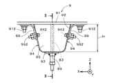
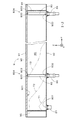
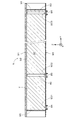
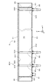
図1は、本発明の一の実施の形態に係る充填処理が行われる鋼床版9の一部を示す図であり、鋼床版9に設けられるUリブ92の長手方向に沿って見た様子を示している。図2は、図1中の矢印II−IIの位置における鋼床版9の断面図である。図1および図2では、互いに直交するX方向、Y方向およびZ方向を矢印にて示している(他の図において同様)。
FIG. 1 is a diagram showing a part of a
Uリブ92は、Y方向に長く、図1に示すように、長手方向(Y方向)に沿って見た形状は、上方((+Z)側)に向かって開口するU字状である。Uリブ92は、下側((−Z)側)に配置される底面部93と、幅方向(X方向)における底面部93の両端から連続して上方へと伸びる2つの側面部94とを備える。各側面部94の上端部は、例えば、すみ肉溶接によりデッキプレート91の下面に接続される。図1および図2のデッキプレート91はほぼ水平である。
The
図2に示すUリブ92の内部には、複数のダイヤフラム95がY方向に間隔を空けて設けられる。互いに隣接する2つのダイヤフラム95、互いに対向する2つの側面部94、および、底面部93によりUリブ92の内部空間が形成され、当該内部空間の上側は、デッキプレート91により閉塞される。すなわち、鋼床版9では、Uリブ92およびデッキプレート91により囲まれる密閉空間90が形成される。密閉空間90は、Uリブ92の長手方向に長く、Y方向は、密閉空間90の長手方向でもある。以下の説明では、一の密閉空間90に着目するとともに、密閉空間90の(−Y)側のダイヤフラム95および(+Y)側のダイヤフラム95をそれぞれ「第1ダイヤフラム95」および「第2ダイヤフラム95」と呼ぶ。
A plurality of
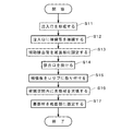
図3は、密閉空間90に対する充填材の充填処理の流れを示す図である。充填処理では、まず、第1ダイヤフラム95の近傍において、底面部93を貫通する孔931(後述するように、充填材の密閉空間90内への注入に利用される孔であり、以下、「注入口931」という。)が形成される(ステップS11)。
FIG. 3 is a diagram showing the flow of the filling process of the filler into the sealed
図4は、第1ダイヤフラム95近傍におけるUリブ92の底面図である。注入口931は、X方向における底面部93のおよそ中央に形成され、第1ダイヤフラム95の近傍にて密閉空間90に開口する。また、底面部93において注入口931の周囲には、注入口931よりも直径が小さい複数の孔939(以下、「ボルト挿入孔939」という。)も形成される。注入口931および複数のボルト挿入孔939は、底面部93の下方からのドリル作業により容易に形成可能である。
FIG. 4 is a bottom view of the
注入口931および複数のボルト挿入孔939が形成されると、注入口931に接続管81が接続される(ステップS12)。詳細には、接続管81には、底面部93の下面((−Z)側の面であり、密閉空間90とは反対側の面)に沿って広がるフランジ部811が設けられ、フランジ部811には複数の貫通孔が設けられる。当該複数の貫通孔の相対位置関係は、複数のボルト挿入孔939の相対位置関係と同じである。また、各ボルト挿入孔939には、ワンサイドボルト812が挿入される。ワンサイドボルト812に対する所定の操作により、密閉空間90内の部位が塑性変形によりボルト挿入孔939よりも大きく広がり、密閉空間90内にボルト頭部が形成される。フランジ部811の各貫通孔はワンサイドボルト812(の軸部)に嵌め込まれる。そして、ワンサイドボルト812にナット813を締め付けることにより、接続管81が底面部93の下面に固定される。接続管81は、ビニールホース等を介して充填材の供給源に接続される。接続管81の固定では、軸部の外側面から進退自在な可動突起部を有するボルト等が利用されてもよい(以下同様)。
When the
続いて、図2のUリブ92では、長手方向(Y方向)に関して、第1ダイヤフラム95と第2ダイヤフラム95との間の所定の位置において、底面部93に貫通孔932が形成される。図4の注入口931と同様に、貫通孔932は、X方向における底面部93のおよそ中央に形成される。また、貫通孔932の周囲には、図4のボルト挿入孔939と同様に複数のボルト挿入孔が形成される。貫通孔932および複数のボルト挿入孔は、底面部93の下方からのドリル作業により容易に形成可能である。各ボルト挿入孔には、ワンサイドボルトが挿入される。貫通孔932には、真っ直ぐな補助排出管82が底面部93の下方から挿入される。補助排出管82は、例えば塩化ビニルにて形成され、軽量かつ加工性に優れている。補助排出管82は、取付部89を用いて底面部93に固定される(ステップS13)。
Subsequently, in the
図5は、取付部89の断面図であり、取付部89の中心軸J1を含む断面を示している。取付部89は、取付本体891と、2つの取付ナット部892と、2つのゴム輪893と、フランジ部894とを備える。取付本体891および2つの取付ナット部892は所定の中心軸J1を中心とする略筒状であり、取付本体891の両端部には、2つの取付ナット部892がそれぞれ螺合可能である。取付ナット部892は、中心軸J1側に突出する環状突出部895を有し、取付本体891の端面と環状突出部895との間にゴム輪893が配置される。一方の取付ナット部892において、環状突出部895のゴム輪893とは反対側の面には、フランジ部894が接着等により固定される。フランジ部894には複数の貫通孔が設けられる。当該複数の貫通孔の相対位置関係は、貫通孔932の周囲に形成される複数のボルト挿入孔の相対位置関係と同じである。取付ナット部892およびフランジ部894は、1つの部材として形成されてもよい。
FIG. 5 is a cross-sectional view of the mounting
補助排出管82を底面部93に固定する際には、貫通孔932を介して密閉空間90内に配置した補助排出管82の一方の端部(以下、「当接端部」という。)が、密閉空間90の上面901、すなわち、密閉空間90内におけるデッキプレート91の下面に当接する(図2参照)。そして、この状態で、密閉空間90外に位置する補助排出管82の他方の端部に、取付部89が嵌め込まれる。このとき、取付部89において、フランジ部894が設けられる取付ナット部892が上側(底面部93側)に配置されるとともに、2つの取付ナット部892は取付本体891に対して緩められている。フランジ部894の各貫通孔は、貫通孔932の周囲のワンサイドボルトに嵌め込まれる。ワンサイドボルトにナットを締め付けることにより、フランジ部894が底面部93の下面に固定される。
When the
続いて、取付本体891を回転することにより、上側の取付ナット部892と取付本体891の端部とが締め付けられる。また、下側の取付ナット部892を回転することにより、当該取付ナット部892と取付本体891の端部とが締め付けられる。各取付ナット部892と取付本体891との締め付けにより、ゴム輪893が圧縮され、ゴム輪893を介して補助排出管82が取付部89に固定される。このようにして、密閉空間90の下部から上部に向かって伸びる補助排出管82が底面部93に固定される。
Subsequently, by rotating the mounting
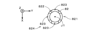
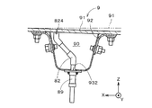
図6は、補助排出管82の当接端部821近傍を拡大して示す図であり、図7は、当接端部821の環状端面822を示す図である。中心軸J1に沿って見た場合に、環状端面822は、円環状の面である。環状端面822は、多角形や矩形の環状であってもよい。環状端面822には、中心軸J1を中心とする周方向に沿って複数の切欠部823が設けられる。換言すると、環状端面822は、周方向に沿って凹凸形状を有する。補助排出管82では、環状端面822が密閉空間90の上面901に当接する。このような構造により、補助排出管82は、密閉空間90の上面901に近接した位置にて開口する。複数の切欠部823の集合は、補助排出口824として捉えられる。
FIG. 6 is an enlarged view showing the vicinity of the
補助排出管82が固定されると、図2のUリブ92では、(+Y)側の第2ダイヤフラム95の近傍において、底面部93に貫通孔933が形成される。貫通孔933は、X方向における底面部93のおよそ中央に形成される。また、貫通孔933の周囲には、図4のボルト挿入孔939と同様に複数のボルト挿入孔が形成される。貫通孔933および複数のボルト挿入孔は、底面部93の下方からのドリル作業により容易に形成可能である。各ボルト挿入孔には、ワンサイドボルトが挿入される。貫通孔933には、真っ直ぐな排出管83が底面部93の下方から挿入される。排出管83の構造は、補助排出管82と同様であり、補助排出管82と同様の作業により、排出管83が取付部89を用いて底面部93に固定される。排出管83における複数の切欠部833の集合は、密閉空間90の上面901に近接した位置にて開口する端部開口となり、排出口834として捉えられる。このようにして、密閉空間90において第2ダイヤフラム95近傍の上部にて開口する排出口834が設けられる(ステップS14)。
When the
続いて、Uリブ92に対して補強板99が取り付けられる(ステップS15)。詳細には、図1に示すUリブ92の各側面部94において、複数の孔部942がY方向に沿って形成される。各孔部942には、ワンサイドボルト992が挿入される。また、当該側面部94の近傍においてデッキプレート91の下面に複数のスタッド912が溶接により取り付けられる。複数のスタッド912は、Y方向に並ぶ。
Subsequently, the reinforcing
補強板99は、長い板状の部材を、長手方向に垂直な幅方向に対して湾曲させたものである。補強板99には、複数のワンサイドボルト992および複数のスタッド912が挿入される複数の孔部が設けられる。補強板99の孔部に挿入されるワンサイドボルト992およびスタッド912にナットを締め付けることにより、補強板99がUリブ92の側面部94およびデッキプレート91に対して固定される。補強板99により、Uリブ92の外側面(すなわち、側面部94の密閉空間90とは反対側の面)とデッキプレート91の下面とが接続される。なお、Uリブ92に対するドリル作業、すなわち、注入口931、貫通孔932,933、ボルト挿入孔および孔部942の形成は一括して行われてもよく、この場合、ステップS11〜S15が部分的に並行して行われると捉えることができる。
The reinforcing
補強板99が取り付けられると、充填材の供給源から図2の接続管81を介して注入口931に所定の流量にて充填材が供給され、注入口931から密閉空間90内に充填材が連続的に充填される(ステップS16)。充填材は、例えば、特開2014−221702号公報(上記特許文献3)に記載の軽量モルタルである。注入口931から密閉空間90内に注入される充填材は、図2中に符号T1,T2を付す二点鎖線にて示すように、注入口931の上方に盛り上がる。その後、充填材が長手方向(Y方向)に垂直な密閉空間90の断面の全体に広がり、符号T3を付す二点鎖線にて示すように、密閉空間90の上面901にも接触しつつ(+Y)側の排出位置に向かって移動する。
When the reinforcing
このとき、充填材に含まれるガスが、充填材の密閉空間90内への注入直後に凝集し、密閉空間90の上面901(デッキプレート91の下面)近傍に比較的大きな空隙が発生することがある。このような空隙は、上方がデッキプレート91の下面に覆われ、他の方向は充填材により囲まれた状態で、周囲の充填材と共に(+Y)側に向かって移動する。空隙内のガスは、補助排出管82の補助排出口824近傍を通過する際に、一部の充填材と共に補助排出管82を介して密閉空間90の外部に排出される。充填材が排出管83の排出口834まで到達すると、排出管83から密閉空間90の外部に充填材が排出される。排出管83から充填材が連続的に排出され始めると、充填材の供給源からの充填材の供給が停止され、密閉空間90内への充填材の充填が完了する。
At this time, the gas contained in the filler aggregates immediately after the filler is injected into the sealed
長手方向に関して、注入口931が開口する位置を注入位置とし、排出口834が設けられる位置を排出位置とすると、補助排出管82が設けられる位置は、充填材の移動途上において、密閉空間90の上面901と接する空隙を除去する補助排出位置として捉えられる。補助排出位置は、長手方向における注入位置と排出位置との間の位置である。補助排出管82は、充填材の供給が停止されるまで、補助排出口824と密閉空間90の外部と継続して接続し、補助排出口824からの空隙内のガスの排出(空隙の除去)が可能である。
Assuming that the position where the
充填の完了から所定時間経過して充填材が硬化すると、図4に示すナット813が緩められてワンサイドボルト812から外され、注入口931における接続管81が取り外される。そして、図8に示す板状の蓋部材84が接続管81に替えて取り付けられる。詳細には、蓋部材84には、接続管81のフランジ部811と同様の複数の貫通孔が設けられており、各貫通孔をワンサイドボルト812に嵌め込んで、ナットがワンサイドボルト812に締め付けられる。これにより、蓋部材84が底面部93の下面に固定され、蓋部材84により注入口931が閉塞される。蓋部材84は、例えば鋼製であり、一定の耐久性が確保される。なお、図8では、密閉空間90に充填された充填材Tに平行斜線を付している。
When the filling material is cured after a predetermined time has elapsed from the completion of filling, the
本実施の形態におけるワンサイドボルトでは、軸部において頭部側に形成されるねじ部と、先端側に形成されるねじ部との間に、ねじ山が形成されない円筒部が設けられる。したがって、頭部側のねじ部に締め付けられたナットが仮に緩んだとしても、先端側のねじ部の存在により当該ナットが落下することが防止される。また、蓋部材84の固定では、いわゆる緩み止めナットが用いられることが好ましい(後述の蓋部材85,86の固定において同様)。
In the one-side bolt in the present embodiment, a cylindrical portion where no thread is formed is provided between a screw portion formed on the head side in the shaft portion and a screw portion formed on the tip side. Therefore, even if the nut fastened to the screw portion on the head side is loosened, the nut is prevented from falling due to the presence of the screw portion on the tip side. In fixing the
また、補助排出管82の取付部89においても、図5の下側の取付ナット部892を回転することにより、当該取付ナット部892が取付本体891の端部に対して緩められる。また、取付本体891を回転することにより、取付本体891が上側の取付ナット部892に対して緩められる。その後、フランジ部894を固定するナットが緩められてワンサイドボルトから外され、取付部89が底面部93および補助排出管82から取り外される。補助排出管82は底面部93の下面に沿って切断され、当該下面から(−Z)側に突出する部分が除去される。そして、板状の蓋部材85が、蓋部材84と同様にして底面部93の下面に固定され、貫通孔932の下側が蓋部材85により覆われる。
Also, in the
排出管83の取付部89も、上記と同様にして取り外される。補助排出管82と同様に、排出管83が底面部93の下面に沿って切断される。そして、板状の蓋部材86が底面部93の下面に固定され、貫通孔933の下側が蓋部材86により覆われる。以上のようにして、蓋部材84〜86がUリブ92に固定され、注入口931および貫通孔932,933が閉塞される(ステップS17)。以上の処理により、密閉空間90に対する充填材の充填処理が完了する。実際には、互いに隣接する2つのダイヤフラム95の間の各密閉空間90に対して、図3の充填処理が行われる。
The
次に、上記充填処理に係る実験について述べる。本実験では、Uリブ92に相当する部材(以下、同様に「Uリブ92」と呼ぶ。)に対して、デッキプレート91に相当する透明なアクリル板を取り付けた試験体を準備した。そして、試験体に対して、図3の充填処理を行った(ただし、補強板99の取付および蓋部材の固定は省略した。以下同様。)。図9では、注入口931、補助排出口824および排出口834の位置を同符号を付す丸にて示している。
Next, an experiment related to the filling process will be described. In this experiment, a test body was prepared in which a transparent acrylic plate corresponding to the
アクリル板を介した観察により、試験体内への充填材の充填中には、注入口931近傍において小さな気泡が断続的に発生することが確認された。このような気泡の集合である空隙は、上方がアクリル板の下面に覆われ、他の方向は充填材により囲まれた状態で、周囲の充填材と共に(+Y)側に向かって移動した。図9の試験体では、空隙が補助排出口824の近傍を通過する際に、空隙内のガスが外部に排出され、空隙が除去された。したがって、充填材の充填後では、図9に示すように、アクリル板を介して確認可能な空隙Gは僅かであった。なお、充填材の充填では、ボルトおよびナットを用いてUリブ92の底面部93に固定される接続管81、補助排出管82および排出管83が底面部93から外れることはなく、これらと底面部93との接続部において充填材が漏出することもなかった。
Observation through the acrylic plate confirmed that small bubbles were intermittently generated in the vicinity of the
本実験では、比較例の処理も行った。比較例の処理では、注入口931に注入ホース(ビニールホース)を接着剤により直接固定した。また、図3のステップS13,S14の作業に替えて、Uリブ92の側面部94におけるアクリル板の下面近傍の位置への貫通孔の形成、および、当該貫通孔への排出ホース(ビニールホース)の挿入を行った。排出ホースは接着剤により側面部94に固定した。図10では、排出ホースが設けられる複数の位置を符号Pを付す三角形にて示している。比較例の処理では、試験体内への充填材の充填中に発生する空隙(特に、X方向の中央近傍の空隙)がうまく除去されず、充填材の充填後において、図10に示すように、多くの大きい空隙Gの存在がアクリル板を介して確認された。
In this experiment, the process of the comparative example was also performed. In the process of the comparative example, an injection hose (vinyl hose) was directly fixed to the
以上に説明したように、図3の充填処理では、密閉空間90の下部から上部に向かって伸びる補助排出管82が、注入位置と排出位置との間の補助排出位置に設けられ、補助排出管82が、密閉空間90の上面901に近接した位置にて開口する。これにより、注入口931から排出口834へと移動する充填材において、密閉空間90の上面901と接する空隙を移動途上において効率よく除去することができる。
As described above, in the filling process of FIG. 3, the
ここで、上記比較例の処理を実際の鋼床版9において仮に行う場合、排出ホース用の貫通孔の形成が行われるが、デッキプレート91に固定された状態のUリブ92においてデッキプレート91の下面近傍に貫通孔を形成することは容易ではない。実際には、Uリブ92の外側面の上部を覆う補強板99も設けられるため、補強板99にも排出ホース用の貫通孔を事前に形成する必要がある。この場合、補強板99の貫通孔とUリブ92の排出ホース用の貫通孔との位置ずれが生じる可能性もある。
Here, when the processing of the comparative example is temporarily performed in the
これに対し、図3の充填処理では、補助排出管82が挿入される貫通孔932が、Uリブ92の下部(上記の例では、底面部93)に形成される。したがって、比較例の処理に比べて貫通孔932を容易に形成する、すなわち、比較例の処理における排出ホースに比べて、補助排出管82を密閉空間90内に容易に設けることが可能である。その結果、密閉空間90に充填された充填材において空隙の発生を容易に抑制することができる。また、比較例の処理のように、補強板99に補助排出管82用の貫通孔を形成する必要もなく、充填処理における作業工数を少なくすることができる。
On the other hand, in the filling process of FIG. 3, a through
また、補助排出管82では、環状端面822が、周方向に沿って凹凸形状を有し、環状端面822が密閉空間90の上面901と当接する。これにより、目視による確認が不可能なUリブ92の内部において、補助排出管82の補助排出口824を、密閉空間90の上面901に近接した位置に配置することが容易に可能となる(排出管83において同様)。なお、環状端面822と密閉空間90の上面901との間の距離が正確に調整可能である場合には、両者の間に微小な隙間が設けられてもよい。
Further, in the
上記充填処理では、底面部93に注入口931を形成する際に、注入口931の周囲に複数のボルト挿入孔939が形成され、注入口931への充填材の供給に利用される接続管81が、複数のボルト挿入孔939に挿入される複数のワンサイドボルト812を用いて底面部93の下面に固定される。これにより、比較例の処理のように接着剤を用いる場合に比べて、接続管81を底面部93により確実に固定することができ、充填材を注入する際に、接続管81が底面部93から外れることが防止される。また、充填材の充填後に、接続管81が取り外され、注入口931を閉塞する蓋部材84が、複数のワンサイドボルト812を用いて底面部93に固定される。これにより、注入口931近傍に位置する硬化した充填材の剥落や、蓋部材84自体の落下を確実に防止することができる。
In the filling process, when the
底面部93に貫通孔932,933を形成する際にも、貫通孔932,933の周囲に複数のボルト挿入孔が形成され、補助排出管82および排出管83を支持する取付部89が、複数のボルト挿入孔に挿入される複数のワンサイドボルトを用いて底面部93の下面に固定される。これにより、補助排出管82および排出管83を底面部93に確実に固定することができ、充填材を充填する際に、補助排出管82および排出管83が底面部93から外れることが防止される。また、充填材の充填後に、取付部89が取り外され、貫通孔932,933を閉塞する蓋部材85,86が、当該複数のワンサイドボルトを用いて底面部93に固定される。これにより、貫通孔932,933近傍に位置する硬化した充填材の剥落や、蓋部材85,86自体の落下を確実に防止することができる。
Also when the through
次に、長手方向(Y方向)に関する注入位置から補助排出位置までの距離について述べる。ここでは、図9の試験体と同様の複数の試験体を準備し、注入位置から補助排出位置までの距離Lを変更しつつ当該複数の試験体に対して図3の充填処理を行った。 Next, the distance from the injection position to the auxiliary discharge position in the longitudinal direction (Y direction) will be described. Here, a plurality of test bodies similar to the test body of FIG. 9 were prepared, and the filling process of FIG. 3 was performed on the plurality of test bodies while changing the distance L from the injection position to the auxiliary discharge position.
注入位置から補助排出位置までの距離Lが、上下方向(Z方向)における密閉空間90の高さH(図1参照)よりも小さい試験体では、補助排出位置が注入位置に近くなり過ぎ、補助排出管82にて除去されずに残留する比較的大きい空隙が観察された。また、注入位置から補助排出位置までの距離Lが、長手方向に関する注入位置から排出位置までの距離L0の半分以上である場合には、補助排出位置が注入位置から離れ過ぎ、注入位置から補助排出位置までの間に比較的大きい空隙の残留が観察された。したがって、密閉空間90に充填された充填材において空隙の発生をより確実に抑制するという観点では、長手方向に関する注入位置から補助排出位置までの距離Lが、上下方向における密閉空間90の高さH以上であり、長手方向に関して、補助排出位置が排出位置よりも注入位置に近いことが好ましい。
In the test body in which the distance L from the injection position to the auxiliary discharge position is smaller than the height H (see FIG. 1) of the sealed
また、複数の試験体内への充填材の充填中に補助排出管82を介して排出される充填材の量を調べた。図11は、注入位置から補助排出位置までの距離Lと充填材の排出量との関係を示す図である。図11の横軸は、注入位置から補助排出位置までの距離Lを密閉空間90の高さHで割った(L/H)の値を示し、縦軸は、充填材の充填中に補助排出管82から排出される充填材の量V1を、補助排出管82および排出管83から排出される充填材の総排出量Vで割った(V1/V)の値を示す。
Further, the amount of the filler discharged through the
図11から判るように、(L/H)の値が大きくなるに従って、(V1/V)の値は小さくなる傾向がある。詳細には、(L/H)の値が1.5以上である場合に、(V1/V)の値は大幅に低下する。したがって、密閉空間90内への充填材の充填が完了する前に、補助排出管82から充填材が過度に排出されることを防止する(充填材の無駄を低減する)には、長手方向に関する注入位置から補助排出位置までの距離Lが、上下方向における密閉空間90の高さHの1.5倍以上であることが好ましいといえる。実際には、(L/H)の値が1.5近傍である場合には、充填材の充填の際に、補助排出管82からの充填材の排出と、排出管83からの充填材の排出とがほぼ同時に発生した。
As can be seen from FIG. 11, the value of (V1 / V) tends to decrease as the value of (L / H) increases. Specifically, when the value of (L / H) is 1.5 or more, the value of (V1 / V) is significantly reduced. Therefore, in order to prevent the filler from being excessively discharged from the
ところで、充填材の充填の完了直前に、注入口931の上方近傍において発生した空隙は、補助排出管82まで到達せずに、注入位置と補助排出位置との間の位置で残留する場合がある。補助排出位置を注入位置に近づける((L/H)の値を小さくする)ことにより、上記空隙の発生は抑制されるが、補助排出管82から排出される充填材の量が増加してしまう。
By the way, there is a case where the gap generated in the vicinity of the upper portion of the
次に、注入位置と補助排出位置との間の位置における空隙の発生を抑制する好ましい処理例について説明する。図12は、充填処理の他の例を説明するための図であり、鋼床版9の断面図である。図12は、図2に対応する。本処理例では、補助排出管82と異なるもう1つの補助排出管82aがUリブ92に設けられる。本処理例の説明では、補助排出管82,82aをそれぞれ「第1補助排出管82」および「第2補助排出管82a」と呼ぶ。
Next, a preferable processing example for suppressing generation of a gap at a position between the injection position and the auxiliary discharge position will be described. FIG. 12 is a view for explaining another example of the filling process, and is a cross-sectional view of the
図3のステップS13では、第1補助排出管82の底面部93への固定に加えて、第2補助排出管82aの底面部93への固定が行われる。詳細には、図12のUリブ92では、長手方向(Y方向)に関して、注入口931と貫通孔932との間において、貫通孔932と同様の貫通孔932aが底面部93に形成される。注入口931から貫通孔932aまでのY方向の距離(中心間距離)は、例えば密閉空間90の高さ未満であり、当該高さの1/3以上である。図12の例では、当該距離は、当該高さの2/3であり、貫通孔932aの位置は、補助排出位置よりも注入位置に近い。X方向に関する貫通孔932aの位置は、注入口931とほぼ同じである。
In step S13 in FIG. 3, in addition to fixing the first
また、貫通孔932aの周囲には、複数のボルト挿入孔が形成され、各ボルト挿入孔には、ワンサイドボルトが挿入される。貫通孔932aには、真っ直ぐな第2補助排出管82aが底面部93の下方から挿入される。第2補助排出管82aの構造は、第1補助排出管82と同様であり、第1補助排出管82と同様の作業により、第2補助排出管82aが取付部89を用いて底面部93に固定される。第2補助排出管82aにおいても、複数の切欠部823の集合が、補助排出口824として捉えられる。
A plurality of bolt insertion holes are formed around the through-
実際には、第1補助排出管82および第2補助排出管82aのそれぞれには、バルブが設けられたビニールホース等が接続される。バルブの開閉により、各管を開放した状態と、閉塞した状態とが切り替えられる。各管を開放した状態では、密閉空間90と外部とが当該管を介して空間的に連続する。各管を閉塞した状態では、密閉空間90と外部とが当該管を介しては空間的に連続しない。排出管83にも、同様のビニールホース等が接続される。
Actually, a vinyl hose or the like provided with a valve is connected to each of the first
ステップS16において、注入口931から密閉空間90内への充填材の充填を開始する際には、第2補助排出管82aが閉塞され、第1補助排出管82および排出管83が開放される。そして、充填材の供給源から接続管81を介して注入口931に所定の流量にて充填材が供給され、注入口931から密閉空間90内に充填材が連続的に充填される。排出管83から充填材が連続的に排出され始めると、供給源から注入口931への充填材の供給流量が低減される(例えば、上記流量の1/3の流量に低減される。)。排出管83から所定量(例えば、20リットル)の充填材が排出されると、充填材の充填の完了直前に到達したものとして、排出管83が閉塞される。また、排出管83の閉塞とほぼ同時に、第2補助排出管82aが開放される。その後、第1補助排出管82も閉塞される。
In step S16, when the filling of the filler from the
第2補助排出管82aの開放により、第2補助排出管82aから充填材が連続的に排出され始める。第2補助排出管82aから所定量(例えば、5リットル)の充填材が排出されると、第2補助排出管82aが閉塞される。第2補助排出管82aを閉塞する際には、第2補助排出管82aから排出される充填材にガスが混入していない、すなわち、充填材のみが連続的に排出されていることが確認されることが好ましい。その後、充填材の供給源からの充填材の供給が停止され、密閉空間90内への充填材の充填が完了する。なお、第1補助排出管82および排出管83を閉塞するタイミングは、適宜変更されてよい。貫通孔932aを覆う蓋部材の固定については、上記処理と同様である。
By opening the second
図9および図10を参照して説明した実験と同様の試験体において、第2補助排出管82aの取付を追加した上記充填処理を行ったところ、注入位置と補助排出位置との間において、アクリル板(密閉空間90の上面901)と接する大きな空隙は発生しなかった。補助排出位置と排出位置との間も同様である。
In the same specimen as the experiment described with reference to FIGS. 9 and 10, the above filling process with the addition of the second
以上に説明したように、本処理例では、第1補助排出管82がUリブ92に設けられる際に、注入位置と補助排出位置との間の位置において、第2補助排出管82aがさらに設けられる。第2補助排出管82aは、密閉空間90の下部から上部に向かって伸びるとともに、密閉空間90の上面901に近接した位置にて開口する。そして、第2補助排出管82aを閉塞した状態で、注入口931から密閉空間90内への充填材の充填が開始され、充填材の充填の完了直前において、第2補助排出管82aが開放される。これにより、充填材の充填の完了直前に、注入口931の上方近傍において発生している空隙を第2補助排出管82aを利用して除去することができ、注入位置と補助排出位置との間の位置における空隙の発生を抑制することが可能となる。
As described above, in the present processing example, when the first
上記充填材の充填処理では様々な変形が可能である。 Various modifications are possible in the filling process of the filler.
図13に示すように、長手方向(Y方向)に垂直な断面においてデッキプレート91が、水平なX方向に対して傾斜する場合には、X方向に関して密閉空間90の中央からずれた位置に、補助排出口824が配置されてもよい(排出口834において同様)。具体的には、補助排出口824は、当該断面において密閉空間90の最も高い位置(最も(+Z)側の位置)近傍に配置されることが好ましく、これにより、充填材の移動途上において空隙をより効率よく除去することが可能となる。なお、図13では、ほぼ水平なデッキプレート91を二点鎖線にて示している。
As shown in FIG. 13, when the
上記実施の形態では、密閉空間90の両端に位置する第1ダイヤフラム95および第2ダイヤフラム95の近傍に注入位置および排出位置が設定されるが、例えば、長手方向における密閉空間90の中央近傍の高さが両端よりも高い場合等には、両端に注入口931が設けられ、中央近傍に排出口834が設けられてもよい。同様に、長手方向における密閉空間90の中央近傍の高さが両端よりも低い場合等には、中央近傍に注入口931が設けられ、両端に排出口834が設けられてもよい。このように、Uリブ92の状態等に応じて、注入位置は長手方向における密閉空間90の任意の位置に設定されてよく、排出位置も、密閉空間90において注入位置から長手方向に離れた任意の位置に設定されてよい。好ましい充填処理では、密閉空間90において水平面に対する勾配が生じている場合に、注入口931は、最も低い位置近傍に配置され、排出口834は、最も高い位置近傍に配置される。
In the above embodiment, the injection position and the discharge position are set in the vicinity of the
図14に示すように、貫通孔932は、Uリブ92の側面部94の下部(例えば、Z方向における側面部94の下半分)において、補強板99と重ならない位置に形成されてもよい。この場合も、密閉空間90の下部から上部に向かって伸びるとともに、密閉空間90の上面901に近接した位置にて開口する補助排出管82を貫通孔932を介して設けることが可能である(貫通孔932aおよび第2補助排出管82a、並びに、貫通孔933および排出管83において同様)。
As shown in FIG. 14, the through
一方、密閉空間90の上面901に対向する底面部93に貫通孔932を形成する場合には、補助排出管82のZ方向の位置が自在に調整可能であるため、補助排出口824を密閉空間90の上面901に近接した位置に配置することが容易に可能となる(貫通孔932aおよび第2補助排出管82a、並びに、貫通孔933および排出管83において同様)。
On the other hand, when the through-
充填材の充填処理において求められる作業効率等によっては、貫通孔932に挿入された補助排出管82が接着剤によりUリブ92に固定されてもよい(接続管81、第2補助排出管82aおよび排出管83において同様)。
The
注入口931は、Uリブ92の側面部94に設けられてもよく、また、排出管83における排出口834と同様に、密閉空間90内に配置される管状部材の端部開口が注入口とされてもよい。排出口834は、密閉空間90における排出位置の上部にて開口すればよく、鋼床版9の構造等によっては、側面部94に形成される貫通孔等が排出口とされてもよい。
The
上記充填処理は、Uリブ92およびデッキプレート91を有する鋼床版9において、Uリブ92およびデッキプレート91により囲まれる密閉空間90内への充填材の充填に特に適しているが、一の方向に長い密閉空間を有する他の構造物において、当該密閉空間内への充填材の充填に利用されてよい。上記充填処理では、鋼床版9のように上方からの密閉空間へのアクセス(密閉空間の上面における排出口等の形成)が困難な場合でも、空隙の発生を抑制しつつ当該密閉空間内に充填材を適切に充填することが可能である。充填材はモルタル以外の材料であってよい。
The above-described filling process is particularly suitable for filling the closed
上記実施の形態および各変形例における構成は、相互に矛盾しない限り適宜組み合わされてよい。 The configurations in the above-described embodiments and modifications may be combined as appropriate as long as they do not contradict each other.
9 鋼床版
81 接続管
82,82a 補助排出管
83 排出管
84〜86 蓋部材
90 密閉空間
91 デッキプレート
92 Uリブ
93 底面部
94 側面部
99 補強板
812,992 ワンサイドボルト
822 環状端面
824 補助排出口
834 排出口
901 (密閉空間の)上面
931 注入口
932,933 貫通孔
939 ボルト挿入孔
L (注入位置から補助排出位置までの)距離
S11〜S17 ステップ
T 充填材
9
Claims (9)
a)一の方向に長い密閉空間を有する構造物において、前記一の方向における前記密閉空間の所定の注入位置にて開口する注入口を設ける工程と、
b)前記密閉空間において前記注入位置から前記一の方向に離れた排出位置の上部にて開口する排出口を設ける工程と、
c)前記注入位置と前記排出位置との間の補助排出位置において、前記密閉空間の下部から上部に向かって伸びるとともに、前記密閉空間の上面に近接した位置にて開口する補助排出管を設ける工程と、
d)前記注入口から前記密閉空間内に充填材を充填する工程と、
を備えることを特徴とする充填方法。 A method of filling a filler,
a) In a structure having a sealed space long in one direction, a step of providing an inlet opening at a predetermined injection position of the sealed space in the one direction;
b) providing a discharge port that opens at an upper portion of the discharge position away from the injection position in the one direction in the sealed space;
c) A step of providing an auxiliary discharge pipe extending from the lower portion of the sealed space toward the upper portion and opening at a position close to the upper surface of the sealed space at the auxiliary discharge position between the injection position and the discharge position. When,
d) filling the sealed space with the filler from the inlet;
A filling method comprising:
前記構造物が、前記密閉空間の前記上面に対向する底面部を有し、
前記c)工程において、前記補助排出管が、前記底面部に設けられる貫通孔に挿入されることを特徴とする充填方法。 The filling method according to claim 1,
The structure has a bottom surface portion facing the top surface of the sealed space;
In the step c), the auxiliary discharge pipe is inserted into a through hole provided in the bottom surface portion.
前記補助排出管の環状端面が、周方向に沿って凹凸形状を有し、
前記c)工程において、前記環状端面が前記密閉空間の前記上面と当接することを特徴とする充填方法。 The filling method according to claim 1 or 2,
The annular end surface of the auxiliary discharge pipe has an uneven shape along the circumferential direction,
In the step c), the annular end surface is in contact with the upper surface of the sealed space.
前記一の方向に関する前記注入位置から前記補助排出位置までの距離が、上下方向における前記密閉空間の高さ以上であり、前記一の方向に関して、前記補助排出位置が前記排出位置よりも前記注入位置に近いことを特徴とする充填方法。 A filling method according to any one of claims 1 to 3,
The distance from the injection position to the auxiliary discharge position in the one direction is equal to or higher than the height of the sealed space in the vertical direction, and the auxiliary discharge position is more in the injection position than the discharge position in the one direction. A filling method characterized by being close to.
前記構造物が、前記密閉空間の前記上面に対向する底面部を有し、
前記a)工程において、前記底面部に前記注入口が形成されるとともに、前記底面部における前記注入口の周囲に複数のボルト挿入孔が形成され、
前記d)工程において、前記複数のボルト挿入孔に挿入される複数のボルトを用いて前記底面部の下面に固定される接続管を介して前記注入口に前記充填材が供給され、
前記充填材の充填後に、前記接続管が取り外され、前記注入口を閉塞する蓋部材が前記複数のボルトを用いて前記底面部に固定されることを特徴とする充填方法。 A filling method according to any one of claims 1 to 4,
The structure has a bottom surface portion facing the top surface of the sealed space;
In the step a), the inlet is formed in the bottom portion, and a plurality of bolt insertion holes are formed around the inlet in the bottom portion,
In the step d), the filler is supplied to the inlet through a connecting pipe fixed to the lower surface of the bottom surface using a plurality of bolts inserted into the plurality of bolt insertion holes,
After the filling material is filled, the connecting pipe is removed, and a lid member that closes the injection port is fixed to the bottom surface using the plurality of bolts.
前記構造物が、前記密閉空間の前記上面に対向する底面部を有し、
前記底面部に設けられる貫通孔に挿入された排出管の端部開口が、前記排出口であることを特徴とする充填方法。 A filling method according to any one of claims 1 to 5,
The structure has a bottom surface portion facing the top surface of the sealed space;
The filling method, wherein an end opening of a discharge pipe inserted into a through hole provided in the bottom surface portion is the discharge port.
前記c)工程において、前記注入位置と前記補助排出位置との間の位置において、前記密閉空間の下部から上部に向かって伸びるとともに、前記密閉空間の前記上面に近接した位置にて開口するもう1つの補助排出管が設けられ、
前記d)工程において、前記もう1つの補助排出管を閉塞した状態で、前記注入口から前記密閉空間内への前記充填材の充填が開始され、前記充填材の充填の完了直前において、前記もう1つの補助排出管が開放されることを特徴とする充填方法。 A filling method according to any one of claims 1 to 6,
In the step c), at the position between the injection position and the auxiliary discharge position, it extends from the lower part to the upper part of the sealed space and opens at a position close to the upper surface of the sealed space. Two auxiliary discharge pipes are provided,
In the step d), the filling of the filler from the inlet into the sealed space is started in a state where the other auxiliary discharge pipe is closed, and immediately before the filling of the filler is completed, A filling method characterized in that one auxiliary discharge pipe is opened.
前記構造物が、Uリブおよびデッキプレートを有する鋼床版であり、
前記密閉空間が、前記Uリブおよび前記デッキプレートにより囲まれる空間であることを特徴とする充填方法。 A filling method according to any one of claims 1 to 7,
The structure is a steel deck with U ribs and deck plates;
The filling method, wherein the sealed space is a space surrounded by the U-rib and the deck plate.
前記d)工程の前に、前記Uリブの外側面と前記デッキプレートの下面とを接続する補強板を取り付ける工程をさらに備えることを特徴とする充填方法。 The filling method according to claim 8,
The filling method further comprising a step of attaching a reinforcing plate that connects the outer surface of the U-rib and the lower surface of the deck plate before the step d).
Priority Applications (1)
| Application Number | Priority Date | Filing Date | Title |
|---|---|---|---|
| JP2016090616A JP6663787B2 (en) | 2016-04-28 | 2016-04-28 | Filling method |
Applications Claiming Priority (1)
| Application Number | Priority Date | Filing Date | Title |
|---|---|---|---|
| JP2016090616A JP6663787B2 (en) | 2016-04-28 | 2016-04-28 | Filling method |
Publications (2)
| Publication Number | Publication Date |
|---|---|
| JP2017198003A true JP2017198003A (en) | 2017-11-02 |
| JP6663787B2 JP6663787B2 (en) | 2020-03-13 |
Family
ID=60238967
Family Applications (1)
| Application Number | Title | Priority Date | Filing Date |
|---|---|---|---|
| JP2016090616A Active JP6663787B2 (en) | 2016-04-28 | 2016-04-28 | Filling method |
Country Status (1)
| Country | Link |
|---|---|
| JP (1) | JP6663787B2 (en) |
Citations (6)
| Publication number | Priority date | Publication date | Assignee | Title |
|---|---|---|---|---|
| JPS6335999A (en) * | 1986-07-31 | 1988-02-16 | 株式会社熊谷組 | Tunnel lining method |
| JP2001323785A (en) * | 2000-05-12 | 2001-11-22 | Osaka Bosui Constr Co Ltd | Filling method of filling material |
| JP2003311727A (en) * | 2002-04-18 | 2003-11-05 | Ishikawajima Constr Materials Co Ltd | Method and apparatus for manufacturing synthetic segment |
| JP2008285870A (en) * | 2007-05-17 | 2008-11-27 | Hanshin Expressway Co Ltd | Method of reinforcing closed rib steel floor slab |
| US20090077758A1 (en) * | 2007-09-21 | 2009-03-26 | Groupe Canam Inc. | Bridge deck panel |
| JP2014221702A (en) * | 2013-05-14 | 2014-11-27 | 阪神高速道路株式会社 | Lightweight infilling mortar composition |
-
2016
- 2016-04-28 JP JP2016090616A patent/JP6663787B2/en active Active
Patent Citations (6)
| Publication number | Priority date | Publication date | Assignee | Title |
|---|---|---|---|---|
| JPS6335999A (en) * | 1986-07-31 | 1988-02-16 | 株式会社熊谷組 | Tunnel lining method |
| JP2001323785A (en) * | 2000-05-12 | 2001-11-22 | Osaka Bosui Constr Co Ltd | Filling method of filling material |
| JP2003311727A (en) * | 2002-04-18 | 2003-11-05 | Ishikawajima Constr Materials Co Ltd | Method and apparatus for manufacturing synthetic segment |
| JP2008285870A (en) * | 2007-05-17 | 2008-11-27 | Hanshin Expressway Co Ltd | Method of reinforcing closed rib steel floor slab |
| US20090077758A1 (en) * | 2007-09-21 | 2009-03-26 | Groupe Canam Inc. | Bridge deck panel |
| JP2014221702A (en) * | 2013-05-14 | 2014-11-27 | 阪神高速道路株式会社 | Lightweight infilling mortar composition |
Also Published As
| Publication number | Publication date |
|---|---|
| JP6663787B2 (en) | 2020-03-13 |
Similar Documents
| Publication | Publication Date | Title |
|---|---|---|
| WO2007145477A1 (en) | Precast concrete segment having connecting structure using steel duct, and connecting structure thereof | |
| JP2009097223A (en) | Method of filling grout into mechanical joint, pc member connection method, beam-column connection portion construction method, beam-column joint portion construction method, floor member and pc wall member connection method, pc member connection structure, beam-column connection structure, beam-column joint portion structure, and floor and wall connection structure | |
| JP2016161083A (en) | Working jig | |
| JP6497957B2 (en) | Rehabilitation pipe position adjustment spacer | |
| JP6120681B2 (en) | Repair member for existing pipeline and underground drainage facility equipped with the same | |
| JP2017198003A (en) | Filling method | |
| KR101879277B1 (en) | An reinforcement method for repair of underground structures | |
| JP5584641B2 (en) | Method for fixing shear reinforcement member | |
| JP2019120056A (en) | Waterproof structure for suspended scaffolding | |
| JP6471043B2 (en) | Cylinder repair member, underground drainage facility including the same, and cylinder repair method | |
| JP2012036655A (en) | Method of reclaiming sewerage manhole and the manhole | |
| JP2021059897A (en) | Plug for concrete member | |
| JP3897354B1 (en) | Manhole repair and reinforcement methods | |
| JP2008261145A (en) | Hollow steel pipe reinforcement method for power transmission tower | |
| JPH04306398A (en) | Repairing method of concrete wall surface | |
| CN110259487A (en) | A kind of tunnel waterstop stationary fixture and its construction method | |
| JP4879627B2 (en) | Steel shell concrete segment manufacturing method | |
| JP6254875B2 (en) | Pipe reinforcement method, pipe renewal method and pipe reinforcement structure | |
| KR0140738B1 (en) | Repair method of reinforced concrete column and its structure | |
| JP2011001786A (en) | Float section repair method and device for building finish material | |
| KR101771194B1 (en) | Repair/reinforcement method of land reclamation type using Steel wire rope | |
| CN102817472A (en) | Shoring moldboard for preventing edge of pipeline from seeping | |
| KR101268843B1 (en) | Charging method for infill material using planar end panel | |
| JP5356199B2 (en) | Containment structure for inner surface of through opening | |
| JP2006292058A (en) | Flanged pipe joint and manufacturing method thereof |
Legal Events
| Date | Code | Title | Description |
|---|---|---|---|
| A621 | Written request for application examination |
Free format text: JAPANESE INTERMEDIATE CODE: A621 Effective date: 20190111 |
|
| A521 | Request for written amendment filed |
Free format text: JAPANESE INTERMEDIATE CODE: A523 Effective date: 20190913 |
|
| A711 | Notification of change in applicant |
Free format text: JAPANESE INTERMEDIATE CODE: A711 Effective date: 20190913 |
|
| RD01 | Notification of change of attorney |
Free format text: JAPANESE INTERMEDIATE CODE: A7426 Effective date: 20190913 |
|
| A521 | Request for written amendment filed |
Free format text: JAPANESE INTERMEDIATE CODE: A821 Effective date: 20190913 |
|
| RD03 | Notification of appointment of power of attorney |
Free format text: JAPANESE INTERMEDIATE CODE: A7423 Effective date: 20191015 |
|
| A977 | Report on retrieval |
Free format text: JAPANESE INTERMEDIATE CODE: A971007 Effective date: 20191021 |
|
| A131 | Notification of reasons for refusal |
Free format text: JAPANESE INTERMEDIATE CODE: A131 Effective date: 20191031 |
|
| A521 | Request for written amendment filed |
Free format text: JAPANESE INTERMEDIATE CODE: A523 Effective date: 20191226 |
|
| TRDD | Decision of grant or rejection written | ||
| A01 | Written decision to grant a patent or to grant a registration (utility model) |
Free format text: JAPANESE INTERMEDIATE CODE: A01 Effective date: 20200130 |
|
| A61 | First payment of annual fees (during grant procedure) |
Free format text: JAPANESE INTERMEDIATE CODE: A61 Effective date: 20200217 |
|
| R150 | Certificate of patent or registration of utility model |
Ref document number: 6663787 Country of ref document: JP Free format text: JAPANESE INTERMEDIATE CODE: R150 |
|
| R250 | Receipt of annual fees |
Free format text: JAPANESE INTERMEDIATE CODE: R250 |
|
| R250 | Receipt of annual fees |
Free format text: JAPANESE INTERMEDIATE CODE: R250 |