JP2017198110A - Variable valve control device of internal combustion engine - Google Patents
Variable valve control device of internal combustion engine Download PDFInfo
- Publication number
- JP2017198110A JP2017198110A JP2016087888A JP2016087888A JP2017198110A JP 2017198110 A JP2017198110 A JP 2017198110A JP 2016087888 A JP2016087888 A JP 2016087888A JP 2016087888 A JP2016087888 A JP 2016087888A JP 2017198110 A JP2017198110 A JP 2017198110A
- Authority
- JP
- Japan
- Prior art keywords
- valve
- combustion engine
- internal combustion
- exhaust
- knock
- Prior art date
- Legal status (The legal status is an assumption and is not a legal conclusion. Google has not performed a legal analysis and makes no representation as to the accuracy of the status listed.)
- Pending
Links
Images

Classifications
-
- Y—GENERAL TAGGING OF NEW TECHNOLOGICAL DEVELOPMENTS; GENERAL TAGGING OF CROSS-SECTIONAL TECHNOLOGIES SPANNING OVER SEVERAL SECTIONS OF THE IPC; TECHNICAL SUBJECTS COVERED BY FORMER USPC CROSS-REFERENCE ART COLLECTIONS [XRACs] AND DIGESTS
- Y02—TECHNOLOGIES OR APPLICATIONS FOR MITIGATION OR ADAPTATION AGAINST CLIMATE CHANGE
- Y02T—CLIMATE CHANGE MITIGATION TECHNOLOGIES RELATED TO TRANSPORTATION
- Y02T10/00—Road transport of goods or passengers
- Y02T10/10—Internal combustion engine [ICE] based vehicles
- Y02T10/12—Improving ICE efficiencies
Landscapes
- Output Control And Ontrol Of Special Type Engine (AREA)
- Combined Controls Of Internal Combustion Engines (AREA)
Abstract
【課題】外部EGRの分配の気筒間差の大きい場合でも燃費を向上させることができる内燃機関の可変動弁制御装置を提供すること。【解決手段】吸気弁12の開閉時期を変更可能な吸気側可変動弁機構13と、排気弁22の開閉時期を変更可能な排気側可変動弁機構23と、エンジン2のノッキング振動の大きさに応じたノック信号を出力するノックセンサ47と、ノックセンサ47の出力するノック信号に基づいて算出した気筒毎のノック強度に基づいて外部EGRの気筒間差が大きいと判定した場合、バルブ開閉時期マップを内部EGR主体のバルブ開閉時期マップに変更して内部EGRガスの量を増やすように変更するECU3と、を備える。【選択図】図1A variable valve control apparatus for an internal combustion engine capable of improving fuel efficiency even when a difference between cylinders in distribution of external EGR is large. An intake side variable valve mechanism 13 capable of changing an opening / closing timing of an intake valve 12, an exhaust side variable valve mechanism 23 capable of changing an opening / closing timing of an exhaust valve 22, and a magnitude of knocking vibration of an engine 2. When it is determined that the difference between the cylinders of the external EGR is large based on the knock intensity for each cylinder calculated based on the knock signal output from the knock sensor 47 and the knock signal output from the knock sensor 47, the valve opening / closing timing ECU 3 for changing the map to a valve opening / closing timing map mainly composed of internal EGR so as to increase the amount of internal EGR gas. [Selection] Figure 1
Description
本発明は、内燃機関の可変動弁制御装置に関する。 The present invention relates to a variable valve control apparatus for an internal combustion engine.
内燃機関において、排気をEGR(Exhaust Gas Recirculation)ガスとして吸気側に還流させるEGR装置を備えることにより、排気のNOx低減および燃費の改善を実現するシステムが知られている。 An internal combustion engine is known that has an EGR device that recirculates exhaust gas to the intake side as EGR (Exhaust Gas Recirculation) gas, thereby realizing NOx reduction of exhaust gas and improvement of fuel consumption.
特許文献1には、EGRが導入されている際、ノックセンサによるノック信号から気筒ごとにノック強度を検出し、気筒間空燃比のバラつきやEGRの気筒別分配のバラつきを、ノッキングを起こしている気筒から判別することが開示されている。 In Patent Document 1, when EGR is introduced, knock strength is detected for each cylinder from a knock signal from a knock sensor, and knocking is caused by variation in the air-fuel ratio between cylinders and variation in EGR distribution among cylinders. Discrimination from a cylinder is disclosed.
この特許文献1に記載のものにおいては、ノッキングと判断した場合、点火時期を全気筒一律に、または気筒別にリタードし、ノッキングを回避している。 In the thing of this patent document 1, when it is judged that it is knocking, the ignition timing is retarded uniformly for all cylinders or for each cylinder to avoid knocking.
しかしながら、EGRの分配の気筒間差は、内燃機関の個体差や環境差により大きく異なる。EGRの分配の気筒間差の大きい内燃機関の場合、点火時期を全気筒一律にリタードすると、ノッキングが発生していない気筒でもリタードされてしまい、燃費の悪化につながる。気筒別にリタードを行なっても、気筒の平均トルクの低下による燃費の悪化、気筒別トルク差の増大によるNVH(Noise, Vibration, Harshness)の悪化につながる。 However, the difference in EGR distribution between cylinders varies greatly depending on individual differences and environmental differences among internal combustion engines. In the case of an internal combustion engine in which the difference in EGR distribution between cylinders is large, if the ignition timing is uniformly retarded for all cylinders, even the cylinders in which knocking has not occurred are retarded, leading to deterioration in fuel consumption. Even if the retarding is performed for each cylinder, the fuel efficiency is deteriorated due to the decrease in the average torque of the cylinder, and the NVH (Noise, Vibration, Harshness) is deteriorated due to the increase in the torque difference among the cylinders.
そこで、本発明は、外部EGRの分配の気筒間差の大きい場合でも燃費を向上させることができる内燃機関の可変動弁制御装置を提供することを目的としている。 Accordingly, an object of the present invention is to provide a variable valve control apparatus for an internal combustion engine that can improve fuel efficiency even when the difference between cylinders in the distribution of external EGR is large.
上記課題を解決するため本発明は、内燃機関の排気の一部を外部EGRガスとして吸気側へ還流させる排気還流管と、前記内燃機関の運転状態に基づいて前記外部EGRガスの還流量を調整するEGRバルブと、前記内燃機関のノッキング振動を検出するノックセンサと、前記内燃機関の吸気弁または排気弁の少なくとも一方の開閉時期を制御して、排気の一部を内部EGRガスとして燃焼室内に導入させるとともに前記内部EGRガスの量を調整する制御部と、を備え、前記制御部は、前記ノックセンサの検出結果に基づいて前記内燃機関の気筒毎のノック強度を検出し、前記気筒毎のノック強度に基づいて前記内部EGRガスの量を変更するものである。 In order to solve the above problems, the present invention provides an exhaust gas recirculation pipe that recirculates a part of exhaust gas of an internal combustion engine to the intake side as external EGR gas, and adjusts the recirculation amount of the external EGR gas based on the operating state of the internal combustion engine. And an open / close timing of at least one of the intake valve and the exhaust valve of the internal combustion engine to control a part of the exhaust as internal EGR gas in the combustion chamber And a control unit that adjusts the amount of the internal EGR gas and detects the knock intensity of each cylinder of the internal combustion engine based on the detection result of the knock sensor. The amount of the internal EGR gas is changed based on the knock strength.
このように本発明によれば、外部EGRの分配の気筒間差の大きい場合でも燃費を向上させることができる内燃機関の可変動弁制御装置を提供することができる。 Thus, according to the present invention, it is possible to provide a variable valve control apparatus for an internal combustion engine that can improve fuel efficiency even when the difference between cylinders in the distribution of the external EGR is large.
以下、図面を参照して、本発明の実施形態に係る内燃機関の可変動弁制御装置について詳細に説明する。 Hereinafter, a variable valve control apparatus for an internal combustion engine according to an embodiment of the present invention will be described in detail with reference to the drawings.
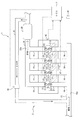
図1において、本発明の一実施形態に係る内燃機関の可変動弁制御装置を搭載した車両1は、内燃機関型のエンジン2と、制御部としてのECU(Engine Control Unit)3とを含んで構成されている。
In FIG. 1, a vehicle 1 equipped with an internal combustion engine variable valve control apparatus according to an embodiment of the present invention includes an internal combustion
エンジン2は、少なくとも1つ以上、例えば4つの気筒を有する直列4気筒で構成されている。なお、エンジン2は、直列4気筒に限らず、例えばV型エンジン等であってもよいし、気筒数も特に4つに限定されるものではない。
The
エンジン2は、不図示のピストン、シリンダ、コネクティングロッド等を備え、ピストンが気筒を2往復する間に吸気行程、圧縮行程、膨張行程及び排気行程からなる一連の4行程を行なう4サイクルのエンジンによって構成されている。
The
シリンダに収納されたピストンは、コネクティングロッドを介してクランクシャフトに連結されている。コネクティングロッドは、ピストンの往復運動をクランクシャフトの回転運動に変換するようになっている。 The piston housed in the cylinder is connected to the crankshaft via a connecting rod. The connecting rod converts the reciprocating motion of the piston into the rotational motion of the crankshaft.
シリンダヘッドには、点火プラグ4と、吸気ポート11と、排気ポート21とが設けられている。点火プラグ4は、燃焼室内に電極を突出させた状態でシリンダヘッドに配設され、ECU3によってその点火時期が調整される。
The cylinder head is provided with an ignition plug 4, an
吸気ポート11には、空気を燃焼室に導入するためのインテークマニホールド14が設けられている。インテークマニホールド14は、外気を吸入するための吸気管15に接続されている。この吸気管15の内部には、吸気ポート11と連通する吸気通路15aが形成されている。
The
吸気ポート11には、吸気弁12が設けられている。吸気弁12は、吸気通路15aと燃焼室とを連通または遮断するように開閉されるようになっている。吸気弁12の開閉は、吸気側可変動弁機構13によって行なわれるようになっている。
The
吸気側可変動弁機構13としては、例えば電磁石とスプリング等から構成された電磁アクチュエータにより吸気弁12の開閉を行う電磁式の可変動弁機構を用いることができる。具体的には、吸気側可変動弁機構13は、電磁石の励磁によって吸気弁12に固定された可動部を吸引することで、スプリングによって常時閉弁方向に付勢されている吸気弁12を開弁方向に移動させるようになっている。
As the intake side
なお、吸気側可変動弁機構13としては、電磁アクチュエータに替えて油圧アクチュエータを用いた油圧式の可変動弁機構を用いてもよい。また、吸気側可変動弁機構13として、主カムおよび副カム等のカム部材を用いて吸気弁12の開閉時期を変更可能な機械式の可変動弁機構を用いても構わない。
The intake side
さらに、この吸気側可変動弁機構13は、例えば電磁石に対する励磁電流がECU3によって調整されることにより、吸気弁12の開閉時期とともに吸気弁12のリフト量を連続的に変化させることが可能な構成であってもよい。
Further, the intake side
排気ポート21には、燃焼室のなかで混合気の燃焼によって発生した排ガスを車外に排出するためのエキゾーストマニホールド24が設けられている。エキゾーストマニホールド24は、排気管25に接続されている。この排気管25の内部には、排気ポート21と連通する排気通路25aが形成されている。
The
排気ポート21には、排気弁22が設けられている。排気弁22は、排気通路25aと燃焼室とを連通または遮断するように開閉されるようになっている。排気弁22の開閉は、排気側可変動弁機構23によって行なわれるようになっている。
The
排気側可変動弁機構23は、上述した吸気側可変動弁機構13と同様の構成であるため、詳細な説明を省略するが、電磁石の励磁、非励磁がECU3によって制御されることで、排気弁22の開閉時期が任意に変更される。なお、排気側可変動弁機構23として、電磁アクチュエータに替えて油圧アクチュエータを用いた油圧式の可変動弁機構を用いてもよい。また、排気側可変動弁機構23として、主カムおよび副カム等のカム部材を用いて排気弁22の開閉時期を変更可能な機械式の可変動弁機構を用いても構わない。したがって、ECU3は、排気弁22の開弁期間を容易に調整することができる。
Since the exhaust side
この排気管25には、三元触媒26が設けられている。三元触媒26は、エンジン2の燃焼室から排出された排ガス、すなわち既燃ガスを浄化するようになっている。
A three-
このエンジン2には、吸気通路15aと排気通路25aとを連通する排気還流管41が設けられている。排気還流管41は、排気の一部を吸気側に還流させるEGRを行なわせるようになっている。この排気還流管41には、排気の還流量を調整する排気還流制御弁としてのEGRバルブ42が設けられている。この排気還流管41によるEGRを外部EGRという。
The
EGRバルブ42は、ECU3に電気的に接続されている。EGRバルブ42は、ECU3からの指令信号に応じてバルブ開度が制御されることで、吸気側に還流させる排気の量を調整するようになっている。
The
ECU3は、CPU(Central Processing Unit)と、RAM(Random Access Memory)と、ROM(Read Only Memory)と、フラッシュメモリと、入力ポートと、出力ポートとを備えたコンピュータユニットによって構成されている。 The ECU 3 includes a computer unit that includes a central processing unit (CPU), a random access memory (RAM), a read only memory (ROM), a flash memory, an input port, and an output port.
このコンピュータユニットのROMには、各種制御定数や各種マップ等とともに、当該コンピュータユニットをECU3として機能させるためのプログラムが記憶されている。すなわち、CPUがROMに記憶されたプログラムを実行することにより、当該コンピュータユニットは、ECU3として機能する。 The ROM of the computer unit stores a program for causing the computer unit to function as the ECU 3 along with various control constants and various maps. That is, the computer unit functions as the ECU 3 when the CPU executes a program stored in the ROM.
ECU3の入力ポートには、クランク角度センサ45、アクセル開度センサ46、ノックセンサ47等の各種センサ類が接続されている。
Various sensors such as a
クランク角度センサ45は、エンジン2の回転に伴い所定クランク角度毎に矩形状のクランク角信号を出力する。ECU3は、このクランク角信号に基づいてエンジン2の機関回転数であるエンジン回転数を算出する。
The
アクセル開度センサ46は、運転者による図示しないアクセルペダルの踏み込み量をアクセル開度として検出する。ノックセンサ47は、エンジン2のノッキング振動を検出し、ノッキング振動の大きさに応じたノック信号を出力する。
The
一方、ECU3の出力ポートには、上述の点火プラグ4、吸気側可変動弁機構13、排気側可変動弁機構23、EGRバルブ42等の各種制御対象類が接続されている。
On the other hand, various control objects such as the above-described ignition plug 4, intake side
ECU3は、運転者の操作によるアクセル開度に基づきエンジン2の要求負荷を算出し、その要求負荷に応じてエンジン2の吸入空気量や燃料噴射量や点火時期を算出する。そして、ECU3は、算出した吸入空気量や燃料噴射量や点火時期になるように不図示のスロットルバルブやインジェクタや点火プラグ4を制御してエンジン2の運転状態を制御する。
The ECU 3 calculates the required load of the
ECU3は、上述した吸気側可変動弁機構13及び排気側可変動弁機構23をそれぞれ制御することによって吸気弁12及び排気弁22の開閉時期を変更して、吸気弁12及び排気弁22の開弁期間を調整するようになっている。ここで、吸気弁12及び排気弁22の開閉時期を変更するとは、例えば、吸気弁12及び排気弁22の閉弁時期を進角あるいは遅角することを意味する。
The ECU 3 changes the opening / closing timing of the
さらに、ECU3は、吸気弁12の開弁期間と排気弁22の開弁期間とがオーバラップするオーバラップ期間の長さを、エンジン回転数とエンジン負荷の大きさとに応じて調整するようになっている。ECU3は、吸気弁12と排気弁22の開閉時期を制御することにより、排気ポート21より排出された排気ガスの一部を内部EGRガスとして燃焼室内や吸気ポート11、インテークマニホールド14に導入する内部EGRを行なわせるようになっている。
Further, the ECU 3 adjusts the length of the overlap period in which the valve opening period of the
外部EGRガスと内部EGRガスとのトータルのEGRガス量は、エンジン2の運転状態に応じて目標量が実験的に求められ、この目標量に基づいて外部EGRガスの量と内部EGRガスの量が制御される。
The total EGR gas amount of the external EGR gas and the internal EGR gas is experimentally obtained as a target amount according to the operating state of the
ECU3は、エンジン2の運転状態に応じて外部EGRを実行させる(オン)か、または実行させない(オフ)か、を切り替えるようになっている。例えば、ECU3は、エンジン回転数とエンジン負荷とによってオンまたはオフが決まる外部EGRマップにより外部EGRのオンとオフを切り替える。この外部EGRマップは、外部EGRをオンにする外部EGRオン領域と、外部EGRをオフにする外部EGRオフ領域とに分けられていて、エンジン回転数とエンジン負荷とによってどちらの領域に入るかが決まるようになっている。この外部EGRマップは、予め実験的に求められ、ECU3のROMに記憶されている。
The ECU 3 is configured to switch whether the external EGR is executed (ON) or not (OFF) depending on the operating state of the
ECU3は、例えば、エンジン回転数とアクセル開度からエンジン負荷が決まるマップによりエンジン負荷を求めるようになっている。エンジン負荷のマップは、予め実験的に求められ、ECU3のROMに記憶されている。 For example, the ECU 3 obtains the engine load from a map in which the engine load is determined from the engine speed and the accelerator opening. The engine load map is experimentally obtained in advance and stored in the ROM of the ECU 3.
ECU3は、エンジン2の運転状態に応じて内部EGRガスの量を制御するようになっている。例えば、ECU3は、エンジン回転数とエンジン負荷とによってバルブ開閉時期が決まるバルブ開閉時期マップにより吸気弁12及び排気弁22の開閉時期を制御して内部EGRガスの量を制御する。ECU3のROMには、予め実験的に求められた、バルブ開閉時期マップが記憶されている。
The ECU 3 controls the amount of internal EGR gas in accordance with the operating state of the
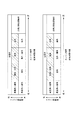
図2は、外部EGR主体のバルブ開閉時期マップの例である。図2の吸気弁開時期は、エンジン回転数とエンジン負荷に応じて、エンジン2が運転可能な最遅角から遅角、進角のどの時期を使うかを示している。排気弁閉時期は、エンジン回転数とエンジン負荷に応じて、エンジン2が運転可能な最進角から進角、遅角のどの時期を使うかを示している。なお、図2では、斜線部分が外部EGRオン領域を示している。
FIG. 2 is an example of a valve opening / closing timing map mainly composed of external EGR. The intake valve opening timing in FIG. 2 indicates which timing from the most retarded angle to the retarded angle or the advanced angle that the
図2に示すように、このマップは、低負荷領域では吸気弁12の開弁を遅角させることでオーバラップ量を増加させて内部EGR量を減少させ、外部EGRガスが導入されるようにし、燃費を稼ぐように形成されている。一方で、排気弁22については、排気弁22の開弁を進角させると排気弁22が早閉じとなり、排気を追い出すことができずポンプロスが悪化するため、特段の変更は行なわない。
As shown in FIG. 2, this map shows that in the low load region, the opening amount of the
また、高負荷領域においては、スロットル開度が増加し、要求トルクが増加するため吸入空気量が多い。そのため、オーバラップ量を増加させ、掃気効果を高める。これにより、内部EGRガスを排出させるようにして、より外部EGRガスの導入を促進させることを可能とする。 In the high load region, the throttle opening increases and the required torque increases, so the amount of intake air is large. Therefore, the amount of overlap is increased and the scavenging effect is enhanced. As a result, the introduction of the external EGR gas can be further promoted by discharging the internal EGR gas.
ECU3は、外部EGRがオンの状態において、気筒毎のノック強度に基づき、外部EGRの気筒間差が大きいと判定したとき、内部EGRガスの量を増やすように、内部EGR主体のバルブ開閉時期マップに切り替える。 When the external EGR is on, the ECU 3 determines that the difference between the external EGR cylinders is large on the basis of the knock strength for each cylinder, so that the internal EGR main valve opening / closing timing map is increased so as to increase the amount of internal EGR gas. Switch to.
ECU3は、各気筒の燃焼時期に基づき、ノックセンサ47のノック信号から各気筒のノック強度を算出する。ECU3は、例えば、ノック強度が最も大きい気筒のノック強度からノック強度が最も小さい気筒のノック強度を減算した値が所定値を超える状態が所定時間Y[s]以上継続した場合、外部EGRの気筒間差が大きいと判定する。所定値及び所定時間は、予め実験的に求められ、ECU3のROMに記憶されている。
The ECU 3 calculates the knock intensity of each cylinder from the knock signal of the
ECU3は、外部EGRの気筒間差が大きいと判定した場合、点火リタードを行なわず、バルブ開閉時期マップを外部EGR主体のバルブ開閉時期マップから内部EGR主体のバルブ開閉時期マップへ切り替える。 If the ECU 3 determines that the difference between the cylinders of the external EGR is large, the ECU 3 switches the valve opening / closing timing map from the valve opening / closing timing map mainly of the external EGR to the valve opening / closing timing map mainly of the internal EGR without performing ignition retard.
図3は、内部EGR主体のバルブ開閉時期マップの例である。図2と同様に、吸気弁開時期は、エンジン2が運転可能な最遅角から遅角、進角のどの時期を使うかを示している。また、排気弁閉時期は、エンジン2が運転可能な最進角から進角、遅角のどの時期を使うかを示している。斜線部分は、外部EGRオン領域を示している。
FIG. 3 is an example of a valve opening / closing timing map mainly composed of internal EGR. Similar to FIG. 2, the intake valve opening timing indicates which timing from the most retarded angle to the retarded angle or the advanced angle at which the
図3に示すように、このマップは、低負荷領域ではオーバラップを大きくとることにより、内部EGRを増やしている。オーバラップが大きいと、排気行程中の吸気管15に内部EGRガスが入ることにより吸気圧が上がるため、外部EGRも減ることになる。
As shown in FIG. 3, this map increases the internal EGR by increasing the overlap in the low load region. If the overlap is large, the intake pressure rises due to the internal EGR gas entering the
また、高負荷領域では、吸気弁開時期を進角させると、低負荷時とは逆に掃気効果により内部EGRが減ってしまうので、遅角させる。高負荷領域の排気弁閉時期は、早閉じにし、既燃ガスを燃焼室に閉じ込め、内部EGRを増やす。 Further, in the high load region, if the intake valve opening timing is advanced, the internal EGR is reduced due to the scavenging effect contrary to the case of low load. When the exhaust valve closes in the high load region, the exhaust valve is closed early, the burned gas is trapped in the combustion chamber, and the internal EGR is increased.
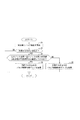
以上のように構成された本実施形態に係る内燃機関の可変動弁制御装置による可変動弁制御処理について、図4を参照して説明する。なお、以下に説明する可変動弁制御処理は、ECU3が動作を開始すると開始され、予め設定された時間間隔で実行される。 A variable valve control process performed by the variable valve control apparatus for an internal combustion engine according to the present embodiment configured as described above will be described with reference to FIG. Note that the variable valve control process described below is started when the ECU 3 starts operation and is executed at a preset time interval.
ステップS1において、ECU3は、ノックセンサ47のノック信号により気筒毎のノック強度を算出する。
In step S <b> 1, the ECU 3 calculates the knock intensity for each cylinder from the knock signal of the
ステップS2において、ECU3は、エンジン回転数とエンジン負荷とからエンジン2の運転状態が外部EGRオン領域か否かを判定する。外部EGRオン領域でないと判定した場合、ECU3は、処理を終了する。
In step S2, the ECU 3 determines whether or not the operating state of the
外部EGRオン領域であると判定した場合、ステップS3において、ECU3は、気筒毎のノック強度のうち、最大のノック強度から最小のノック強度を減算した値が所定値を超える状態が所定時間Y[s]以上継続しているか否かを判定する。 If it is determined that the region is in the external EGR ON region, in step S3, the ECU 3 determines that the value obtained by subtracting the minimum knock strength from the maximum knock strength among the knock strengths for each cylinder exceeds a predetermined value for a predetermined time Y [ s] It is determined whether or not the process continues.
最大のノック強度から最小のノック強度を減算した値が所定値を超える状態が所定時間Y[s]以上継続していると判定した場合、ステップS4において、ECU3は、図3に示すような、内部EGR主体のバルブ開閉時期マップを使用して吸気弁12及び排気弁22を制御する。
When it is determined that the state in which the value obtained by subtracting the minimum knock strength from the maximum knock strength exceeds the predetermined value continues for a predetermined time Y [s] or longer, the ECU 3 in step S4, as shown in FIG. The
一方、最大のノック強度から最小のノック強度を減算した値が所定値を超える状態が所定時間Y[s]以上継続していないと判定した場合、ステップS5において、ECU3は、図2に示すような、外部EGR主体のバルブ開閉時期マップを使用して吸気弁12及び排気弁22を制御する。
On the other hand, when it is determined that the state in which the value obtained by subtracting the minimum knock intensity from the maximum knock intensity exceeds the predetermined value does not continue for the predetermined time Y [s] or longer, the ECU 3 in step S5, as shown in FIG. The
このように、上述の実施形態では、ノックセンサ47の出力するノック信号に基づいて気筒毎のノック強度を算出し、このノック強度に基づいて内部EGRガスの量を変更するECU3を備える。
As described above, the above-described embodiment includes the ECU 3 that calculates the knock intensity for each cylinder based on the knock signal output from the
これにより、ノック強度に基づいて外部EGRの気筒間差が大きいと判定された場合、内部EGRガスの量が変更される。このため、外部EGRの分配の気筒間差の大きい場合でも燃費を向上させることができる。 Thus, when it is determined that the difference between the external EGR cylinders is large based on the knock strength, the amount of the internal EGR gas is changed. For this reason, even when the difference between the cylinders in the distribution of the external EGR is large, the fuel consumption can be improved.
また、ECU3は、ノック強度が最も大きい気筒のノック強度からノック強度が最も小さい気筒のノック強度を減算した値が所定値を超える状態が所定時間Y[s]以上継続した場合、外部EGRの気筒間差が大きいと判定して、内部EGRガスの量を変更する。 Further, when the value obtained by subtracting the knock strength of the cylinder with the smallest knock strength from the knock strength of the cylinder with the largest knock strength continues for a predetermined time Y [s] or longer for a predetermined time Y [s], the ECU 3 It is determined that the difference is large, and the amount of internal EGR gas is changed.
これにより、ノック強度が最も大きい気筒のノック強度からノック強度が最も小さい気筒のノック強度を減算した値が所定値を超える状態が所定時間Y[s]以上継続した場合、外部EGRの気筒間差が大きいと判定される。このため、確実に外部EGRの気筒間差が大きい場合を判定することができ、外部EGRの分配の気筒間差の大きい場合でも燃費を向上させることができる。 As a result, when a state in which the value obtained by subtracting the knock strength of the cylinder having the smallest knock strength from the knock strength of the cylinder having the largest knock strength exceeds the predetermined value continues for a predetermined time Y [s] or longer, the difference between the cylinders of the external EGR Is determined to be large. For this reason, it is possible to reliably determine the case where the difference between the cylinders in the external EGR is large, and it is possible to improve the fuel efficiency even when the difference between the cylinders in the distribution of the external EGR is large.
また、ECU3は、外部EGRの気筒間差が大きいと判定した場合、バルブ開閉時期マップを内部EGR主体のバルブ開閉時期マップに変更して内部EGRガスの量を増やすようにする。 When the ECU 3 determines that the difference between the cylinders in the external EGR is large, the ECU 3 changes the valve opening / closing timing map to a valve opening / closing timing map mainly composed of the internal EGR so as to increase the amount of internal EGR gas.
これにより、外部EGRの気筒間差が大きいと判定された場合、内部EGRガスの量を増やすように変更される。このため、外部EGRの気筒間差が大きい場合に内部EGRガスの量を増やすことができ、外部EGRの分配の気筒間差の大きい場合でも燃費を向上させることができる。 Thereby, when it is determined that the difference between the cylinders of the external EGR is large, the internal EGR gas is changed so as to increase the amount. For this reason, the amount of internal EGR gas can be increased when the difference between the cylinders of the external EGR is large, and the fuel efficiency can be improved even when the difference between the cylinders of the distribution of the external EGR is large.
さらに、内部EGRは、外部EGRに対して熱容量が大きく、圧縮したときに温度が上昇しにくいため、ノッキングを防止することができる。 Furthermore, since the internal EGR has a larger heat capacity than the external EGR and does not easily rise in temperature when compressed, knocking can be prevented.
なお、本実施形態においては、外部EGRの気筒間差が大きい場合に、バルブ開閉時期マップを切り替えたが、同時にEGRバルブ42を閉じたり、EGRバルブ42の開度を変えたりするようにしてもよい。
In this embodiment, the valve opening / closing timing map is switched when the difference between the cylinders of the external EGR is large, but at the same time, the
本発明の実施形態を開示したが、当業者によっては本発明の範囲を逸脱することなく変更が加えられうることは明白である。すべてのこのような修正及び等価物が次の請求項に含まれることが意図されている。 While embodiments of the invention have been disclosed, it will be apparent to those skilled in the art that changes may be made without departing from the scope of the invention. All such modifications and equivalents are intended to be included in the following claims.
1 車両
2 エンジン(内燃機関)
3 ECU(制御部)
12 吸気弁
13 吸気側可変動弁機構
22 排気弁
23 排気側可変動弁機構
41 排気還流管
42 EGRバルブ
45 クランク角度センサ
46 アクセル開度センサ
47 ノックセンサ
1
3 ECU (control unit)
12
Claims (3)
前記内燃機関の運転状態に基づいて前記外部EGRガスの還流量を調整するEGRバルブと、
前記内燃機関のノッキング振動を検出するノックセンサと、
前記内燃機関の吸気弁または排気弁の少なくとも一方の開閉時期を制御して、排気の一部を内部EGRガスとして燃焼室内に導入させるとともに前記内部EGRガスの量を調整する制御部と、を備え、
前記制御部は、前記ノックセンサの検出結果に基づいて前記内燃機関の気筒毎のノック強度を検出し、前記気筒毎のノック強度に基づいて前記内部EGRガスの量を変更する内燃機関の可変動弁制御装置。 An exhaust gas recirculation pipe for recirculating a part of the exhaust gas of the internal combustion engine to the intake side as external EGR gas;
An EGR valve that adjusts a recirculation amount of the external EGR gas based on an operating state of the internal combustion engine;
A knock sensor for detecting knocking vibration of the internal combustion engine;
A control unit that controls the opening / closing timing of at least one of the intake valve and the exhaust valve of the internal combustion engine, introduces a part of the exhaust gas into the combustion chamber as an internal EGR gas, and adjusts the amount of the internal EGR gas. ,
The control unit detects a knock intensity for each cylinder of the internal combustion engine based on a detection result of the knock sensor, and changes the amount of the internal EGR gas based on the knock intensity for each cylinder. Valve control device.
Priority Applications (1)
| Application Number | Priority Date | Filing Date | Title |
|---|---|---|---|
| JP2016087888A JP2017198110A (en) | 2016-04-26 | 2016-04-26 | Variable valve control device of internal combustion engine |
Applications Claiming Priority (1)
| Application Number | Priority Date | Filing Date | Title |
|---|---|---|---|
| JP2016087888A JP2017198110A (en) | 2016-04-26 | 2016-04-26 | Variable valve control device of internal combustion engine |
Publications (1)
| Publication Number | Publication Date |
|---|---|
| JP2017198110A true JP2017198110A (en) | 2017-11-02 |
Family
ID=60237554
Family Applications (1)
| Application Number | Title | Priority Date | Filing Date |
|---|---|---|---|
| JP2016087888A Pending JP2017198110A (en) | 2016-04-26 | 2016-04-26 | Variable valve control device of internal combustion engine |
Country Status (1)
| Country | Link |
|---|---|
| JP (1) | JP2017198110A (en) |
Cited By (1)
| Publication number | Priority date | Publication date | Assignee | Title |
|---|---|---|---|---|
| JP2017198109A (en) * | 2016-04-26 | 2017-11-02 | スズキ株式会社 | Exhaust gas recirculation control device of internal combustion engine |
Citations (5)
| Publication number | Priority date | Publication date | Assignee | Title |
|---|---|---|---|---|
| JP2007032364A (en) * | 2005-07-25 | 2007-02-08 | Toyota Motor Corp | Intake system abnormality detection device |
| JP2007239529A (en) * | 2006-03-07 | 2007-09-20 | Fujitsu Ten Ltd | Misfire/normality determination device |
| JP2008157087A (en) * | 2006-12-22 | 2008-07-10 | Honda Motor Co Ltd | Knock detection device |
| JP2013151874A (en) * | 2012-01-24 | 2013-08-08 | Daihatsu Motor Co Ltd | Spark-ignited internal combustion engine |
| WO2015033371A1 (en) * | 2013-09-03 | 2015-03-12 | Yasueda Shinji | Abnormal combustion detection device for engine and abnormal combustion detection method for engine |
-
2016
- 2016-04-26 JP JP2016087888A patent/JP2017198110A/en active Pending
Patent Citations (5)
| Publication number | Priority date | Publication date | Assignee | Title |
|---|---|---|---|---|
| JP2007032364A (en) * | 2005-07-25 | 2007-02-08 | Toyota Motor Corp | Intake system abnormality detection device |
| JP2007239529A (en) * | 2006-03-07 | 2007-09-20 | Fujitsu Ten Ltd | Misfire/normality determination device |
| JP2008157087A (en) * | 2006-12-22 | 2008-07-10 | Honda Motor Co Ltd | Knock detection device |
| JP2013151874A (en) * | 2012-01-24 | 2013-08-08 | Daihatsu Motor Co Ltd | Spark-ignited internal combustion engine |
| WO2015033371A1 (en) * | 2013-09-03 | 2015-03-12 | Yasueda Shinji | Abnormal combustion detection device for engine and abnormal combustion detection method for engine |
Cited By (1)
| Publication number | Priority date | Publication date | Assignee | Title |
|---|---|---|---|---|
| JP2017198109A (en) * | 2016-04-26 | 2017-11-02 | スズキ株式会社 | Exhaust gas recirculation control device of internal combustion engine |
Similar Documents
| Publication | Publication Date | Title |
|---|---|---|
| US7004148B2 (en) | Control apparatus for internal combustion engine | |
| US8851050B2 (en) | Spark-ignition engine control method and system | |
| CN105637202B (en) | The control device of engine | |
| WO2011122014A1 (en) | Engine control system | |
| JP5802229B2 (en) | Ignition control device for internal combustion engine | |
| JP2005127212A (en) | Control device for internal combustion engine | |
| JP4873249B2 (en) | Control device for vehicle engine | |
| US9217378B2 (en) | Controller for internal combustion engine | |
| CN108625996B (en) | Method and system for engine control | |
| CN110966103A (en) | Cylinder stop switching device | |
| JP2014020265A (en) | Control device for internal combustion engine | |
| US10669953B2 (en) | Engine control system | |
| JP2009041540A (en) | Control unit for gasoline engine | |
| JP2006037812A (en) | Engine valve characteristic control device | |
| JP6358007B2 (en) | Control device for internal combustion engine | |
| JP6610401B2 (en) | Control device for internal combustion engine | |
| CN106593667A (en) | Control system of internal combustion engine | |
| JP5851463B2 (en) | Valve timing control device for internal combustion engine | |
| JP2017198110A (en) | Variable valve control device of internal combustion engine | |
| JP6090641B2 (en) | Control device for internal combustion engine | |
| JP6607138B2 (en) | Exhaust gas recirculation control device for internal combustion engine | |
| JP6848412B2 (en) | Internal combustion engine control device | |
| JP4425839B2 (en) | Control device for internal combustion engine | |
| JP6658266B2 (en) | Control device for internal combustion engine | |
| JP4801744B2 (en) | Method and apparatus for operating an internal combustion engine |
Legal Events
| Date | Code | Title | Description |
|---|---|---|---|
| A621 | Written request for application examination |
Free format text: JAPANESE INTERMEDIATE CODE: A621 Effective date: 20181116 |
|
| A977 | Report on retrieval |
Free format text: JAPANESE INTERMEDIATE CODE: A971007 Effective date: 20190621 |
|
| A131 | Notification of reasons for refusal |
Free format text: JAPANESE INTERMEDIATE CODE: A131 Effective date: 20190702 |
|
| A521 | Request for written amendment filed |
Free format text: JAPANESE INTERMEDIATE CODE: A523 Effective date: 20190802 |
|
| A131 | Notification of reasons for refusal |
Free format text: JAPANESE INTERMEDIATE CODE: A131 Effective date: 20200107 |
|
| A521 | Request for written amendment filed |
Free format text: JAPANESE INTERMEDIATE CODE: A523 Effective date: 20200227 |
|
| A02 | Decision of refusal |
Free format text: JAPANESE INTERMEDIATE CODE: A02 Effective date: 20200512 |