JP2017198734A - Camera with built-in stroboscope - Google Patents
Camera with built-in stroboscope Download PDFInfo
- Publication number
- JP2017198734A JP2017198734A JP2016087222A JP2016087222A JP2017198734A JP 2017198734 A JP2017198734 A JP 2017198734A JP 2016087222 A JP2016087222 A JP 2016087222A JP 2016087222 A JP2016087222 A JP 2016087222A JP 2017198734 A JP2017198734 A JP 2017198734A
- Authority
- JP
- Japan
- Prior art keywords
- strobe
- light
- camera
- built
- housing
- Prior art date
- Legal status (The legal status is an assumption and is not a legal conclusion. Google has not performed a legal analysis and makes no representation as to the accuracy of the status listed.)
- Pending
Links
Images


Landscapes
- Stroboscope Apparatuses (AREA)
- Studio Devices (AREA)
- Exposure Control For Cameras (AREA)
Abstract
【課題】複雑且つ高価な構造を備えていなくとも、誰でも簡単に優れた写真を撮ることができるストロボ内蔵カメラを提供する。【解決手段】筐体11と、筐体11の正面に設けられ、被写体から反射した光を受光する撮影レンズ12と、筐体11の上面に設けられ、撮影レンズ12の受光面に対して直交する光出射面を備える上面ストロボと、を有する。【選択図】図1There is provided a camera with a built-in strobe that allows anyone to easily take excellent pictures without having a complicated and expensive structure. A housing 11 is provided on a front surface of the housing 11 to receive light reflected from a subject. The housing 11 is provided on an upper surface of the housing 11 and is orthogonal to a light receiving surface of the photographing lens 12. An upper surface strobe including a light emitting surface. [Selection] Figure 1
Description
本発明は、ストロボを内蔵するストロボ内蔵カメラに関する。 The present invention relates to a camera with a built-in strobe.
従来から、デジタルカメラには内蔵ストロボが設けられてきた。これは、被写体が暗い場合に、当該デジタルカメラの使用者がシャッターボタンを押すと、自動的に或いは事前の操作設定によって内蔵ストロボが起動し、ストロボ発光窓から光が被写体に向って放射されることになる。例えば、特許文献1には、ストロボを内蔵したストロボ内蔵カメラが開示されている。 Conventionally, digital cameras have been provided with built-in strobes. This is because, when the subject is dark, when the user of the digital camera presses the shutter button, the built-in strobe is activated automatically or according to the previous operation settings, and light is emitted toward the subject from the strobe light emission window. It will be. For example, Patent Document 1 discloses a camera with a built-in strobe having a built-in strobe.
しかしながら、ストロボ内蔵カメラと被写体との間にテーブル等の種々の物体が存在している場合、当該物体がストロボ光を浴びてしまい、撮像された写真では本来明るくすべき被写体が暗くなってしまう。一方、ストロボ内蔵カメラと被写体との間に存在する当該物体には比較的に強い光が照射されてしまい、当該物体は撮像された写真では真っ白になってしまい、当該物体を認識することが困難になる。すなわち、撮像された写真は、本来の被写体が暗くて認識しづらいだけでなく、被写体の周囲の物体が真白くなってしまい、非常に出来の悪いものになってしまう。 However, when various objects such as a table are present between the camera with a built-in strobe and the subject, the object is exposed to strobe light, and the subject that should be brightened in the photographed image becomes dark. On the other hand, the object existing between the camera with a built-in flash and the subject is irradiated with relatively strong light, and the object becomes white in the photographed image, and it is difficult to recognize the object. become. That is, the photographed image is not only difficult to recognize because the original subject is dark, but also the objects around the subject are whitened, resulting in a very poor result.
特に、被写体及びその周囲に存在する物体によって反射したストロボ光を受光及び評価して、当該評価結果に応じてストロボの発光量及びISO感度を調整する機能を備えるカメラにおいては、上述した問題が顕著に生じ、被写体が真っ暗な写真になってしまう。これは、被写体に到達するストロボ光量が少ない場合であっても、被写体よりも手間に存在する物体からの反射光を受光してしまい、ストロボ光が十分に届いていると判断されてしまうためである。 In particular, in a camera having a function of receiving and evaluating strobe light reflected by a subject and an object existing around the subject and adjusting the light emission amount and ISO sensitivity of the strobe according to the evaluation result, the above-described problem is remarkable. And the subject becomes a dark picture. This is because even if the amount of strobe light reaching the subject is small, the reflected light from the object that is in trouble compared to the subject is received, and it is determined that the strobe light has reached sufficiently. is there.
本発明はこのような課題に鑑みてなされたものであり、その目的とするところは、特殊且つ高価な構造を備えることなく、誰でも簡単に優れた写真を撮ることができるストロボ内蔵カメラを提供することにある。 The present invention has been made in view of the above problems, and an object of the present invention is to provide a camera with a built-in strobe that allows anyone to easily take excellent photographs without providing a special and expensive structure. There is to do.
上述した目的を達成するため、本発明のストロボ内蔵カメラは、筐体と、前記筐体の正面に設けられ、被写体から反射した光を受光する撮影レンズと、前記筐体の上面に設けられ、前記撮影レンズの受光面に対して直交する光出射面を備える上面ストロボと、を有する。 In order to achieve the above-described object, a camera with a built-in strobe according to the present invention is provided on the front surface of the housing, the photographing lens that receives light reflected from the subject, and the upper surface of the housing. An upper surface strobe having a light emitting surface orthogonal to the light receiving surface of the photographing lens.
本発明においては、ストロボ内蔵カメラの筐体の上面からストロボ光を出射することになるため、ストロボ内蔵カメラと被写体との間に存在する物体の影響を受けることなく、被写体の上方にストロボ光を効率よく照射することができる。従って、特殊且つ高価な構造が用いられていなくとも、誰でも簡単に優れた写真を撮ることができる。 In the present invention, since the strobe light is emitted from the upper surface of the housing of the built-in strobe camera, the strobe light is emitted above the subject without being affected by the object existing between the strobe-equipped camera and the subject. Irradiation can be performed efficiently. Therefore, even if a special and expensive structure is not used, anyone can easily take an excellent photograph.
上述したストロボ内蔵カメラにおいては、前記上面ストロボは、ストロボ光を透過するストロボ窓、及び前記ストロボ窓の露出/遮蔽を行う蓋体を有し、前記蓋体の少なくとも1つの面はストロボ光を反射してもよい。この場合において、前記蓋体を回動自在に支持する蝶番を更に有し、前記蓋体の前記ストロボ窓と対向する面はストロボ光を反射してもよい。これらの場合においては、ストロボ内蔵カメラの後方に出射される光を被写体に向けて放射することができ、被写体に向けた効率よくストロボ光を照射することができる。 In the above-described camera with a built-in strobe, the top strobe has a strobe window that transmits the strobe light and a cover that exposes / shields the strobe window, and at least one surface of the cover reflects the strobe light. May be. In this case, a hinge for rotatably supporting the lid body may be further provided, and a surface of the lid body facing the strobe window may reflect strobe light. In these cases, the light emitted to the rear of the camera with a built-in strobe can be emitted toward the subject, and the strobe light can be efficiently emitted toward the subject.
上述したストロボ内蔵カメラのいずれかにおいて、前記撮影レンズの受光面と平行に配置された光出射面を備える正面ストロボと、前記正面ストロボの発光量と、前記上面ストロボの発光量との比率を制御する発光制御手段と、を有してもよい。これにより、正面ストロボの発光量と上部ストロボの発光量との比率を自在に変更することができるため、被写体の形状及び特性、並びに被写体の周囲の環境に応じて最適なストロボ光の照射を容易に行うことができる。 In any of the cameras with built-in strobes described above, the ratio of the front strobe with a light exit surface arranged in parallel with the light receiving surface of the photographing lens, the amount of light emitted from the front strobe, and the amount of light emitted from the top strobe is controlled. Light emission control means. This makes it possible to freely change the ratio of the amount of light emitted from the front strobe and the amount of light emitted from the upper strobe, making it easy to irradiate optimal strobe light according to the shape and characteristics of the subject and the surrounding environment of the subject. Can be done.
上述したストロボ内蔵カメラのいずれかにおいて、前記正面ストロボ及び前記上部ストロボは、共通する発光源を備えていてもよく、互いに独立した発光源を備えていてもよい。これにより、部品数の削減によりコスト低減を図ること、又はストロボごとに発光量及び色温度等の調整を図ることができる。 In any of the above-described cameras with built-in strobes, the front strobe and the upper strobe may have a common light source or may have light sources independent of each other. Thereby, it is possible to reduce the cost by reducing the number of parts, or to adjust the light emission amount and the color temperature for each strobe.
本発明によれば、特殊且つ高価な構造を備えていなくとも、誰でも簡単に優れた写真を撮ることができる。 According to the present invention, anyone can easily take an excellent photograph without a special and expensive structure.
以下、図面を参照しながら、本発明のストロボ内蔵カメラの好適な実施例を詳細に説明する。なお、本発明は以下に説明する内容に限定されるものではなく、その要旨を変更しない範囲において任意に変更して実施することが可能である。また、各実施例の説明に用いる図面は、いずれも本発明に係るストロボ内蔵カメラを模式的に示すものであって、理解を深めるべく部分的な強調、拡大、縮小、又は省略等を行っており、各構成部分の縮尺や形状等を正確に表すものとはなっていない場合がある。更に、各実施例で用いる様々な数値は、いずれも一例を示すものであり、必要に応じて様々に変更することが可能である。 Hereinafter, preferred embodiments of a camera with built-in flash according to the present invention will be described in detail with reference to the drawings. In addition, this invention is not limited to the content demonstrated below, In the range which does not change the summary, it can change arbitrarily and can implement. In addition, the drawings used for the description of each embodiment schematically show a camera with a built-in strobe according to the present invention, and are partially emphasized, enlarged, reduced, omitted or the like to deepen understanding. In some cases, the scale, shape, etc. of each component are not accurately represented. Furthermore, the various numerical values used in each embodiment are merely examples, and can be variously changed as necessary.
<実施例1>
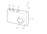
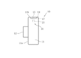
先ず、図1乃至図3を参照しつつ、本発明の一実施形態であるストロボ内蔵カメラ10の構造について説明する。ここで、図1は、本実施例に係るストロボ内蔵カメラ10の斜視図である。また、図2は、本実施例に係るストロボ内蔵カメラ10の側面図である。更に、図3は、本実施例に係るストロボ内蔵カメラ10のストロボ使用時における側面図である。
<Example 1>
First, the structure of a flash built-in
本実施例に係るストロボ内蔵カメラ10は、図1乃至図3からわかるように、直方体状の筐体11に各種の機能部品が設けられている。具体的に、ストロボ内蔵カメラ10は、筐体11の第1の面11a(すなわち、正面)側に撮影レンズ12を有している。また、ストロボ内蔵カメラ10は、筐体11の第2の面11b(すなわち、上面)側に、後述する上面ストロボ窓を遮蔽する蓋体13、及び当該蓋体13を回動自在に支持する蝶番14を有している。更に、ストロボ内蔵カメラ10は、第2の面11b側に電源ボタン15、及びシャッターボタン16を有している。
As can be seen from FIGS. 1 to 3, the
なお、図示しないものの、筐体11の背面(すなわち、第1の面11aの反対側の面)には、モニター、各種のメニューボタン、及び各種の機能スイッチが設けられている(いずれも図示せず)。また、筐体11の第1の面11aには光学ファインダ窓が設けられていてもよく、筐体11の背面には光学ファインダが設けられていてもよい。
Although not shown, a monitor, various menu buttons, and various function switches are provided on the back surface of the housing 11 (that is, the surface opposite to the
本実施例においては、薄板状の筐体11が使用され、一般的な薄型タイプのコンパクトデジタルカメラが構成されているが、筐体11の形状は一眼レフ等の比較的に大型のカメラを構成してもよい。また、電源ボタン15は、ストロボ内蔵カメラ10の電源のオン/オフごとに操作するためのボタンである。また、シャッターボタン16は、ストロボ内蔵カメラ10が撮影モード時において、撮影を開始するためのボタンである。更に、シャッターボタン16は、モニターに表示された各種のメニューの確定及び実行をするためボタンとしても機能する。
In this embodiment, a thin plate-
撮影レンズ12は、被写体から反射した光を受光するためレンズであり、公知のカメラ用のレンズである。本実施例においては、撮影レンズ12が筐体11から突出するようにもうけられているが、筐体11内に内蔵されてもよい。筐体11内に撮影レンズ12が内蔵される場合には、電源ボタン15によるオン状態への移行時に、撮影レンズ12を覆うシャッターが開き、撮影レンズ12が外部に露出するような構造であってもよい。
The photographing
図2及び図3に示すように、蝶番14は蓋体13の一端側(ストロボ内蔵カメラ10の背面側)に設けられており、蓋体13が当該蝶番14を基点として45度回動する。これにより、ストロボ使用時においては、蓋体13が回動して起立した状態となり、筐体11の第2の面11bには上部ストロボ窓17が露出することになる。筐体11の内部にはストロボ光源21が設けられており、当該ストロボ光源21からストロボ光が出射され、上部ストロボ窓17を透過して筐体11の外部に出射されることになる。ストロボ光源21としては、例えば、キセノンランプ等の一般的な光源を使用することができるが、LED光源を使用してもよい。
As shown in FIGS. 2 and 3, the
また、上部ストロボ窓17に対向する蓋体13の表面(すなわち、筐体11の内側に配設される蓋体13の表面)には、反射板の設置又は鏡面加工が施されている。これにより、ストロボ使用時である蓋体13の起立時においては、ストロボ内蔵カメラ10の後方に向けて出射される光は、蓋体13によって反射され、ストロボ内蔵カメラ10の前方に向けて進むことになる。すなわち、ストロボ内蔵カメラ10から出射されるストロボ光は、蓋体13によって反射されることなくストロボ内蔵カメラ10の前方に向けて進む第1ストロボ光Aと、蓋体13によって反射することによってストロボ内蔵カメラ10の前方に向けて進む第2ストロボ光Bとから構成されることになる。このような蓋体13の反射機能により、ストロボ内蔵カメラ10の後方に出射されてしまう無駄な光がなくなり、被写体に向けてストロボ光を効率よく出射することが可能になる。
In addition, the surface of the
なお、本実施例においては、上部ストロボ窓17及びストロボ光源21から上部ストロボ31が構成されている。従って、上部ストロボ31は、筐体11の上面に設けられ、且つ撮影レンズ12の受光面に対して直交する光出射面(上部ストロボ窓17)を備えることになる。
In the present embodiment, the
本実施例においては、上部ストロボ31の発光量は、撮影レンズ12によって受光する光量に応じて、筐体11内部に設けられた制御装置(図示せず)によって自動的に調整されてもよい。また、筐体11の表面に発光量調整ダイヤルを設け、ストロボ内蔵カメラ10の操作者が、上部ストロボ31の発光量を手動で決定してもよい。
In the present embodiment, the light emission amount of the
本実施例に係るストロボ内蔵カメラ10においては、筐体11の第1の面11aにストロボ窓を設けることなく、第2の面11bのみに上部ストロボ窓17を設けている。これにより、被写体の正面に向けて直接的にストロボ光を照射することがなくなり、被写体の上方を明るくするようにストロボ光が照射されることになる。従って、ストロボ内蔵カメラ10と被写体との間に存在する物体にストロボ光が照射されることがなくなり、当該物体によってストロボ光が反射してストロボ内蔵カメラ10に戻ることもない。すなわち、撮像される写真において、当該物体による反射光の影響が生じることがなくなり、被写体が暗く且つ被写体の手前に存在する物体が白く光るような不出来な写真となることもない。特に、上部ストロボ31の発光量を自動調整する場合であっても、ストロボ光が不十分であるにも関わらず、ストロボ光が十分に届いていると判断されることがなくなり、ストロボの発光量の調整をより優れた精度で行うことができる。
In the built-in
本実施例においては、ストロボ窓を設ける位置を上面に変更するということにより、従来において解決することができなった誰でも簡単に優れた写真を撮ることができるという課題を解決することが可能になる。また、特殊又は高価なストロボ装置等を必要としないため、ストロボ内蔵カメラ10のコスト増加をもたらすことがなく、優れた写真を撮像することが可能となっている。
In this embodiment, by changing the position where the strobe window is provided to the upper surface, it is possible to solve the problem that anyone who can not solve the problem can easily take a good picture. Become. Further, since no special or expensive strobe device or the like is required, it is possible to take an excellent photograph without increasing the cost of the
<実施例2>
次に、2つのストロボを有するストロボ内蔵カメラを実施例2として、図4乃至図6を参照しつつ説明する。ここで、図4は、本実施例に係るストロボ内蔵カメラ100の斜視図である。また、図5は、本実施例に係るストロボ内蔵カメラ100の側面図である。更に、図6は、本実施例に係るストロボ内蔵カメラ100のストロボの概略構成図である。
<Example 2>
Next, a camera with a built-in strobe having two strobes will be described as a second embodiment with reference to FIGS. Here, FIG. 4 is a perspective view of the flash built-in camera 100 according to the present embodiment. FIG. 5 is a side view of the strobe camera 100 according to the present embodiment. Furthermore, FIG. 6 is a schematic configuration diagram of a strobe of the built-in strobe camera 100 according to the present embodiment.
本実施例に係るストロボ内蔵カメラ100は、図4に示すように、直方体状の筐体111に各種の機能部品が設けられている。具体的に、ストロボ内蔵カメラ100は、筐体111の第1の面111a(すなわち、正面)側に撮影レンズ112及び正面ストロボ窓113を有している。また、ストロボ内蔵カメラ110は、筐体111の第2の面111b(すなわち、上面)側に電源ボタン115、シャッターボタン116、上部ストロボ窓117、及びストロボ光調整ダイヤル118を有している。
As shown in FIG. 4, the camera with a built-in strobe 100 according to the present embodiment is provided with various functional components in a
なお、図示しないものの、筐体111の背面(すなわち、第1の面111aの反対側の面)には、モニター、光学ファインダ、各種のメニューボタン、及び各種の機能スイッチが設けられている。また、筐体111の第1の面111aには光学ファインダ窓が設けられていてもよく、筐体111の背面には光学ファインダが設けられていてもよい。
Although not shown, a monitor, an optical viewfinder, various menu buttons, and various function switches are provided on the back surface of the casing 111 (that is, the surface opposite to the first surface 111a). Further, an optical finder window may be provided on the first surface 111 a of the
本実施例においても、薄板状の筐体111が使用され、一般的な薄型タイプのコンパクトデジタルカメラが構成されているが、筐体111の形状は一眼レフ等の比較的に大型のカメラを構成してもよい。また、電源ボタン115は、ストロボ内蔵カメラ110の電源のオン/オフごとに操作するためのボタンである。また、シャッターボタン116は、ストロボ内蔵カメラ10が撮影モード時において撮影を開始するためのボタンであるとともに、モニターに表示された各種のメニューの確定及び実行をするためボタンとしても機能する。
Also in this embodiment, a thin plate-
撮影レンズ112は、被写体から反射した光を受光するためレンズであり、公知のカメラ用のレンズである。本実施例においては、撮影レンズ112が筐体111から突出するようにもうけられているが、筐体111内に内蔵されてもよい。
The
図4及び図5から分かるように、正面ストロボ窓113は、撮影レンズ112と同様に、筐体111の第1の面111aに設けられている。すなわち、正面ストロボ窓113は、撮影レンズ112の受光面と平行となるように配設されている。このため、正面ストロボ窓113は被写体と対向することになり、正面ストロボ窓113を透過して出射する正面ストロボ光Cは、被写体に向けて出射することになる。換言すると、正面ストロボ窓113は、当該被写体に向けて正面ストロボ光Cを出射するための光出射面として機能する。
As can be seen from FIGS. 4 and 5, the
一方、上部ストロボ窓117は、筐体111の第2の面111bに設けられているため、撮影レンズ112の受光面と直交するように配設されている。このため、上部ストロボ窓117は被写体と対向することはなく、上部ストロボ窓117を透過して出射する上部ストロボ光Dは、被写体の上方に向けて出射することになる。換言すると、上部ストロボ窓117は、正面ストロボ光Cの光出射面である正面ストロボ窓113に対して直交する光出射面として機能する。
On the other hand, since the
図4及び図6から分かるように、本実施例に係るストロボ内蔵カメラ110の筐体111の内部には、正面ストロボ光C及び上部ストロボ光Dのストロボ光源121が設けられている。また、筐体111の内部には、ストロボ光源121から出射した光を正面ストロボ窓113及び上部ストロボ窓117に対して誘導する調光ミラー122が設けられている。更に、筐体111の内部には、調光ミラー122の反射率を制御する反射率制御部123が設けられている。そして、反射率制御部123は、筐体111の第2の面111bに設けられたストロボ光調整ダイヤル118と電気的に接続している。
As can be seen from FIGS. 4 and 6, a
本実施例においては、正面ストロボ窓113、調光ミラー122、ストロボ光源121から正面ストロボ131が構成され、上部ストロボ窓117、調光ミラー122、ストロボ光源121から上部ストロボ132が構成されている。すなわち、ストロボ光源121及び調光ミラー122は、正面ストロボ131と上部ストロボ132の共通構成部材となっている。そして、正面ストロボ131、上部ストロボ132、反射率制御部123、及びストロボ光調整ダイヤル118から、ストロボ内蔵カメラ110としてのストロボが構成されている。換言すると、本実施例に係るストロボ内蔵カメラ110は、被写体に向けて出射される正面ストロボ光Cの光量(正面ストロボの発光量)、及び被写体の上方に向けて出射される上部ストロボ光Dの光量(上部ストロボの発光量)の比率を制御するストロボが内蔵されていることになる。
In the present embodiment, the
ストロボ光源121としては、例えば、キセノンランプ等の一般的な光源を使用することができるが、LED光源を使用してもよい。また、ストロボ光源121には光源制御部(図示せず)が接続されており、ストロボ光源121から出射される発光量(すなわち、正面ストロボ光Cの光量と上部ストロボ光Dの光量との総和)を調整できるとともに、正面ストロボ光C及び上部ストロボ光Dの色温度を調整できるようにしてもよい。
As the
調光ミラー122は、印加される電圧に応じて反射率が可逆的に変化する特性を有している。例えば、調光ミラー122には、公知のエレクトロミックが用いられる。このような調光ミラー122の特性により、ストロボ光源121から出射された光の一部は、調光ミラー122で反射して正面ストロボ光Cとして正面ストロボ窓113に誘導される。一方、ストロボ光源121から出射された光の残部は、調光ミラー122を透過して上部ストロボ光Dとして上部ストロボ窓117に誘導される。このような調光ミラー122により、正面ストロボ光Cの光量(すなわち、正面ストロボの発光量)と上部ストロボ光Dの光量(すなわち、上部ストロボの発光量)の比率を自在に変更することが可能になる。
The
反射率制御部123は、調光ミラー122に印加する電圧を変化させることにより、調光ミラー122の反射率を制御する。例えば、反射率制御部123は、一般的な電源回路及び演算回路から構成されてもよい。
The
ストロボ光調整ダイヤル118には、例えば、正面ストロボ光Cの光量と上部ストロボ光Dの光量との比率が印字されていてもよい。そして、ストロボ光調整ダイヤル118を所定方向(順方向)に回転させると、正面ストロボ光Cの光量が増加し且つ上部ストロボ光Dの光量が減少するが、ダイヤルを所定方向とは逆方向に回転させると、正面ストロボ光Cの光量が減少し且つ上部ストロボ光Dの光量が増加する構造となっていてもよい。
On the strobe
なお、ストロボ光調整ダイヤル118の設置箇所は上述した場所に限定されることなく、例えば、筐体111の第1の面111aであってもよい。また、ストロボ光調整ダイヤル118に代えて、筐体111の背面に設けられたモニターに正面ストロボ光Cの光量と上部ストロボ光Dの光量との比率を表示し、各種の操作ボタンによって当該比率を変更できるようにしてもよい。
Note that the installation location of the strobe
このようなストロボ内蔵カメラ110のストロボの構造により、ストロボ内蔵カメラ110の使用者がストロボ光調整ダイヤル118を操作すると、反射率制御部123は操作後のストロボ光調整ダイヤル118の状態に応じた反射率を算出し、当該反射率に対応した電圧を調光ミラー122に印加して、調光ミラー122の反射率を調整する。従って、本実施例においては、調光ミラー122、反射率制御部123、及びストロボ光調整ダイヤル118から発光制御手段133が構成されていることになる。
Due to the strobe structure of the built-in
以上のように、本実施例に係るストロボ内蔵カメラ110においては、被写体に向けて発光する正面ストロボ131、及び上方に向けて発光する上部ストロボ132が設けられているものの、正面ストロボ131の発光量と上部ストロボ132の発光量との比率を自在に変更することができるため、被写体の正面に向けた正面ストロボ光Cの照射量を小さく調整しつつ、被写体の上方を明るくするように上部ストロボ光Dの照射量を多く調整することが可能になる。従って、ストロボ内蔵カメラ110と被写体との間に存在する物体に正面ストロボ光Cが照射されたとしても、当該物体による反射光の影響が低減されることになり、被写体の手前に存在する物体が白く光るような不出来な写真となることもない。一方、被写体の上方が明るくなるように上部ストロボ光Dの照射量を多くすることにより、被写体が暗くなることも防止することができる。
As described above, the built-in
すなわち、本実施例においては、ストロボ窓を設ける位置として上面を追加しつつ、正面ストロボ光Cと上部ストロボ光Dとの照射量を調整可能とすることにより、従来において解決することができなった誰でも簡単に優れた写真を撮ることができるという課題を解決することが可能になる。また、特殊又は高価なストロボ装置等を必要としないため、ストロボ内蔵カメラ100のコスト増加をもたらすことがなく、優れた写真を撮像することが可能となっている。 That is, in the present embodiment, it has not been possible to solve the problem in the related art by making it possible to adjust the irradiation amount of the front strobe light C and the upper strobe light D while adding the upper surface as the position where the strobe window is provided. It becomes possible to solve the problem that anyone can easily take excellent photos. In addition, since a special or expensive strobe device or the like is not required, the cost of the camera 100 with built-in strobe is not increased, and excellent photographs can be taken.
また、本実施例に係るストロボ内蔵カメラ100においては、正面ストロボ131の発光量と上部ストロボ132の発光量との比率を自在に変更することができるため、被写体の形状及び特性、並びに被写体の周囲の環境に応じて最適なストロボ光の照射を容易に行うことができる。特に、ストロボ光調整ダイヤル118が筐体111の第2の面111bに設けられているため、撮影を行いながらも当該各ストロボの発光量を容易に調整することが可能になる。
Further, in the camera with a built-in strobe 100 according to the present embodiment, since the ratio of the light emission amount of the
更に、本実施例に係るストロボ内蔵カメラ100においては、正面ストロボ131及び上部ストロボ132の光源が共通のストロボ光源121であるため、部品数が削減されており、コスト低減がなされている。ただし、正面ストロボ131及び上部ストロボ132毎に発光量及び色温度等を調整可能とするために、正面ストロボ131及び上部ストロボ132は互いに独立した光源を備えていてもよい。
Furthermore, in the built-in strobe camera 100 according to the present embodiment, since the light sources of the
なお、上述した発光制御手段により、正面ストロボ131の発光量と上部ストロボ132の発光量との比率を自在に変更することができるものの、ストロボ光によって被写体に生成される影の影響を低減するためにも、上部ストロボ132の発光量をできるかぎり多くすることが好ましい。例えば、ストロボ光源から出射される光を基準に、正面ストロボ131の発光量を2%、上部ストロボ132の発光量を98%とすることが好ましい。従って、正面ストロボ131の発光量と上部ストロボ132の発光量との比率が自動設定されている場合や、カメラの初期設定については、正面ストロボ131の発光量を小さくし(例えば、5%以下)、上部ストロボ132の発光量を大きく(例えば、95%以上)しておくことが好ましい。
In addition, although the ratio of the light emission amount of the
また、本実施例においては、上部ストロボ窓117が常に露出している構造となっていたが、実施例1のような蓋体を設けてもよい。これにより、ストロボ内蔵カメラ100の後方に放射される上部ストロボ光Dの一部を、ストロボ内蔵カメラ100の正面側(すなわち、被写体)に向けて適格に放射することが可能となる。
In the present embodiment, the
10 ストロボ内蔵カメラ
11 筐体
11a 第1の面
11b 第2の面
12 撮影レンズ
13 蓋体
14 蝶番
15 電源ボタン
16 シャッターボタン
17 上部ストロボ窓
21 ストロボ光源(発光源)
31 上部ストロボ
110 ストロボ内蔵カメラ
111 筐体
111a 第1の面
111b 第2の面
112 撮影レンズ
113 正面ストロボ窓
115 電源ボタン
116 シャッターボタン
117 上部ストロボ窓
118 ストロボ光調整ダイヤル
121 ストロボ光源(発光源)
122 調光ミラー
123 反射率制御部
131 正面ストロボ
132 上部ストロボ
133 発光制御手段
DESCRIPTION OF
31
122
Claims (6)
前記筐体の正面に設けられ、被写体から反射した光を受光する撮影レンズと、
前記筐体の上面に設けられ、前記撮影レンズの受光面に対して直交する光出射面を備える上面ストロボと、を有するストロボ内蔵カメラ。 A housing,
A photographic lens that is provided in front of the housing and receives light reflected from the subject;
A camera with a built-in strobe, comprising: a top strobe provided on a top surface of the housing and having a light emitting surface orthogonal to a light receiving surface of the photographing lens.
前記蓋体の少なくとも1つの面はストロボ光を反射する請求項1に記載のストロボ内蔵カメラ。 The upper surface strobe has a strobe window that transmits strobe light, and a lid that exposes / shields the strobe window,
The camera with a built-in strobe according to claim 1, wherein at least one surface of the lid reflects strobe light.
前記蓋体の前記ストロボ窓と対向する面はストロボ光を反射する請求項2に記載のストロボ内蔵カメラ。 A hinge that rotatably supports the lid,
The camera with a built-in strobe according to claim 2, wherein a surface of the lid facing the strobe window reflects strobe light.
前記正面ストロボの発光量と、前記上面ストロボの発光量との比率を制御する発光制御手段と、を有する請求項1乃至3のいずれか1項に記載のストロボ内蔵カメラ。 A front strobe including a light emitting surface arranged in parallel with the light receiving surface of the photographing lens;
4. The camera with built-in flash according to claim 1, further comprising: a light emission control unit that controls a ratio between a light emission amount of the front strobe and a light emission amount of the upper surface strobe. 5.
Priority Applications (1)
| Application Number | Priority Date | Filing Date | Title |
|---|---|---|---|
| JP2016087222A JP2017198734A (en) | 2016-04-25 | 2016-04-25 | Camera with built-in stroboscope |
Applications Claiming Priority (1)
| Application Number | Priority Date | Filing Date | Title |
|---|---|---|---|
| JP2016087222A JP2017198734A (en) | 2016-04-25 | 2016-04-25 | Camera with built-in stroboscope |
Publications (1)
| Publication Number | Publication Date |
|---|---|
| JP2017198734A true JP2017198734A (en) | 2017-11-02 |
Family
ID=60237833
Family Applications (1)
| Application Number | Title | Priority Date | Filing Date |
|---|---|---|---|
| JP2016087222A Pending JP2017198734A (en) | 2016-04-25 | 2016-04-25 | Camera with built-in stroboscope |
Country Status (1)
| Country | Link |
|---|---|
| JP (1) | JP2017198734A (en) |
Citations (13)
| Publication number | Priority date | Publication date | Assignee | Title |
|---|---|---|---|---|
| JPS50136423U (en) * | 1974-04-24 | 1975-11-10 | ||
| JPS52126828U (en) * | 1976-03-22 | 1977-09-27 | ||
| JPH09197525A (en) * | 1996-01-11 | 1997-07-31 | Konica Corp | Film unit with lens |
| JPH1010610A (en) * | 1996-06-24 | 1998-01-16 | Konica Corp | Film unit with lens |
| US5717964A (en) * | 1997-02-18 | 1998-02-10 | Eastman Kodak Company | Camera exposure apparatus having flash tubes for correcting for overexposure |
| JPH10133259A (en) * | 1996-10-31 | 1998-05-22 | Fuji Photo Film Co Ltd | Stroboscopic device |
| JP2001272716A (en) * | 2000-03-27 | 2001-10-05 | Sanyo Electric Co Ltd | Camera with built-in stroboscope |
| JP2005070303A (en) * | 2003-08-22 | 2005-03-17 | Sony Corp | Imaging device |
| JP2005326451A (en) * | 2004-05-12 | 2005-11-24 | Konica Minolta Photo Imaging Inc | Imaging device |
| US20090208198A1 (en) * | 2008-02-14 | 2009-08-20 | Alok Khuntia | Camera integrated with direct and indirect flash units |
| JP2010039025A (en) * | 2008-08-01 | 2010-02-18 | Nikon Corp | Imaging device |
| JP2010266604A (en) * | 2009-05-13 | 2010-11-25 | Canon Inc | Imaging device and flash device |
| KR20150003053U (en) * | 2014-02-03 | 2015-08-12 | 광주대학교산학협력단 | Led light for camera |
-
2016
- 2016-04-25 JP JP2016087222A patent/JP2017198734A/en active Pending
Patent Citations (13)
| Publication number | Priority date | Publication date | Assignee | Title |
|---|---|---|---|---|
| JPS50136423U (en) * | 1974-04-24 | 1975-11-10 | ||
| JPS52126828U (en) * | 1976-03-22 | 1977-09-27 | ||
| JPH09197525A (en) * | 1996-01-11 | 1997-07-31 | Konica Corp | Film unit with lens |
| JPH1010610A (en) * | 1996-06-24 | 1998-01-16 | Konica Corp | Film unit with lens |
| JPH10133259A (en) * | 1996-10-31 | 1998-05-22 | Fuji Photo Film Co Ltd | Stroboscopic device |
| US5717964A (en) * | 1997-02-18 | 1998-02-10 | Eastman Kodak Company | Camera exposure apparatus having flash tubes for correcting for overexposure |
| JP2001272716A (en) * | 2000-03-27 | 2001-10-05 | Sanyo Electric Co Ltd | Camera with built-in stroboscope |
| JP2005070303A (en) * | 2003-08-22 | 2005-03-17 | Sony Corp | Imaging device |
| JP2005326451A (en) * | 2004-05-12 | 2005-11-24 | Konica Minolta Photo Imaging Inc | Imaging device |
| US20090208198A1 (en) * | 2008-02-14 | 2009-08-20 | Alok Khuntia | Camera integrated with direct and indirect flash units |
| JP2010039025A (en) * | 2008-08-01 | 2010-02-18 | Nikon Corp | Imaging device |
| JP2010266604A (en) * | 2009-05-13 | 2010-11-25 | Canon Inc | Imaging device and flash device |
| KR20150003053U (en) * | 2014-02-03 | 2015-08-12 | 광주대학교산학협력단 | Led light for camera |
Similar Documents
| Publication | Publication Date | Title |
|---|---|---|
| JP5071233B2 (en) | Camera and camera system | |
| US8032018B2 (en) | Photographing apparatus having a folding flash unit | |
| JP5163498B2 (en) | Camera system | |
| JP2019200329A (en) | Rotation regulation structure and lighting unit including the same | |
| JP2008256849A (en) | Lighting device | |
| JP5187646B2 (en) | External strobe for digital cameras | |
| JP6657805B2 (en) | Optical equipment | |
| JP2007133316A (en) | Camera accessories and cameras | |
| JP3860037B2 (en) | Camera with flash device | |
| JP2006171087A (en) | Flash device and camera | |
| JP2010266604A (en) | Imaging device and flash device | |
| JP3713691B2 (en) | camera | |
| JP2000089334A (en) | Camera | |
| JP2001215603A (en) | Camera | |
| JP2003330073A (en) | camera | |
| JPH08327886A (en) | Camera with built-in stroboscope | |
| JP2000292682A (en) | Automatic focus adjustment device | |
| JP2005241750A (en) | Display device and camera | |
| JPH11352548A (en) | Film-integrated type camera | |
| US20050212941A1 (en) | Image pickup apparatus | |
| JP2005292591A (en) | Display device and camera | |
| JP2000122112A (en) | Device for detecting wheter shutter is open/closed | |
| JP2004272003A (en) | Imaging device | |
| JPH1172835A (en) | Adapter for close up | |
| JP2000035600A (en) | Zone focus type focus adjusting device of camera |
Legal Events
| Date | Code | Title | Description |
|---|---|---|---|
| A977 | Report on retrieval |
Free format text: JAPANESE INTERMEDIATE CODE: A971007 Effective date: 20180206 |
|
| A131 | Notification of reasons for refusal |
Free format text: JAPANESE INTERMEDIATE CODE: A131 Effective date: 20180221 |
|
| A02 | Decision of refusal |
Free format text: JAPANESE INTERMEDIATE CODE: A02 Effective date: 20180926 |