JP2017200331A - Hand operation cart - Google Patents

Hand operation cart Download PDF

Info

Publication number
JP2017200331A
JP2017200331A JP2016089905A JP2016089905A JP2017200331A JP 2017200331 A JP2017200331 A JP 2017200331A JP 2016089905 A JP2016089905 A JP 2016089905A JP 2016089905 A JP2016089905 A JP 2016089905A JP 2017200331 A JP2017200331 A JP 2017200331A
Authority
JP
Japan
Prior art keywords
plate
wheel
permanent magnet
coil
generator
Prior art date
Legal status (The legal status is an assumption and is not a legal conclusion. Google has not performed a legal analysis and makes no representation as to the accuracy of the status listed.)
Pending
Application number
JP2016089905A
Other languages
Japanese (ja)
Inventor
幸一 笹倉
Koichi Sasakura
幸一 笹倉
Current Assignee (The listed assignees may be inaccurate. Google has not performed a legal analysis and makes no representation or warranty as to the accuracy of the list.)
Star Micronics Co Ltd
Original Assignee
Star Micronics Co Ltd
Priority date (The priority date is an assumption and is not a legal conclusion. Google has not performed a legal analysis and makes no representation as to the accuracy of the date listed.)
Filing date
Publication date
Application filed by Star Micronics Co Ltd filed Critical Star Micronics Co Ltd
Priority to JP2016089905A priority Critical patent/JP2017200331A/en
Publication of JP2017200331A publication Critical patent/JP2017200331A/en
Pending legal-status Critical Current

Links

Images

Landscapes

  • Handcart (AREA)
  • Connection Of Motors, Electrical Generators, Mechanical Devices, And The Like (AREA)
  • Permanent Magnet Type Synchronous Machine (AREA)

Abstract

【課題】発電機を有しながらも組立が簡便で、且つ、操作性の高い手動カートを提供すること。【解決手段】手動カート(10C)は、車体(11)に設けられた軸(21)と、この軸(21)に回転可能に取り付けられた車輪(30)と、この車輪(30)に設けられ車輪(30)が回転することにより発電する発電機(40)と、を備えている。発電機(40)は、車輪(30)の側面に沿って設けられ車輪(30)と共に回転する第1のプレート(41)と、この第1のプレート(41)に保持された永久磁石(43)と、この永久磁石(43)に対向して設けられ第1のプレート(41)と共に回転可能な金属板(45)と、軸(21)に設けられたコイルホルダ(47)と、このコイルホルダ(47)によって保持されたコイル(48)と、を有している。コイル(48)は、永久磁石(43)と金属板(45)との間に位置している。【選択図】図13To provide a manual cart that has a generator and is easy to assemble and has high operability. A manual cart (10C) includes a shaft (21) provided on a vehicle body (11), a wheel (30) rotatably attached to the shaft (21), and a wheel (30). And a generator (40) that generates electricity by rotating the wheel (30). The generator (40) includes a first plate (41) provided along the side surface of the wheel (30) and rotating together with the wheel (30), and a permanent magnet (43) held by the first plate (41). ), A metal plate (45) provided to face the permanent magnet (43) and rotatable with the first plate (41), a coil holder (47) provided on the shaft (21), and the coil And a coil (48) held by a holder (47). The coil (48) is located between the permanent magnet (43) and the metal plate (45). [Selection] Figure 13

Description

本発明は、車輪が回転することにより発電する発電機を備えた手動カートに関する。   The present invention relates to a manual cart including a generator that generates electric power by rotating wheels.

買い物の際に、買い物かごを載せて押すことのできるカートが知られている。このようなカートとして、車輪に発電機が設けられたカートが知られている。発電機は、車輪が回転することにより発電を行う。このような手動カートに関する従来技術として特許文献1に開示される技術がある。   There is known a cart that can be loaded with a shopping cart and pushed when shopping. As such a cart, a cart having a generator on a wheel is known. The generator generates electricity by rotating the wheels. There is a technique disclosed in Patent Document 1 as a conventional technique related to such a manual cart.

図15を参照する。図15は、特許文献1の図2を再掲した図である。符号は、適宜振り直した。   Refer to FIG. FIG. 15 is a diagram showing FIG. 2 of Patent Document 1 again. The reference numerals were reassigned as appropriate.

手動カート100は、車体101に設けられた軸102と、この軸102に回転可能に取り付けられた車輪103と、この車輪103に設けられ車輪103が回転することにより発電する発電機110と、を備えている。   The manual cart 100 includes a shaft 102 provided on the vehicle body 101, a wheel 103 rotatably attached to the shaft 102, and a generator 110 provided on the wheel 103 and generating electric power by rotating the wheel 103. I have.

発電機110は、車輪103に固定され車輪103と共に回転する永久磁石111と、車体101に固定され回転不能なコイル112と、を有している。コイル112、及び、永久磁石111は、軸102を中心として同心円状に配置されている。永久磁石111は、コイル112の外周においてコイル112に対向して設けられていると共に、プッシュナット113によって車輪103に向かって押しつけられている。発電機110は、自転車の車輪に設けられるハブダイナモと同じ構成が採用されている。   The generator 110 includes a permanent magnet 111 that is fixed to the wheel 103 and rotates together with the wheel 103, and a coil 112 that is fixed to the vehicle body 101 and cannot rotate. The coil 112 and the permanent magnet 111 are arranged concentrically around the shaft 102. The permanent magnet 111 is provided on the outer periphery of the coil 112 so as to face the coil 112, and is pressed toward the wheel 103 by the push nut 113. The generator 110 has the same configuration as a hub dynamo provided on a bicycle wheel.

ところで、自転車の車輪の直径は、ハブダイナモの直径に対して、少なくとも数倍以上大きい。このため、車輪が回転する力に対して、ハブダイナモが車輪の回転に抗しようとする力は、極めて小さい。   By the way, the diameter of the bicycle wheel is at least several times larger than the diameter of the hub dynamo. For this reason, the force that the hub dynamo tries to resist the rotation of the wheel against the force of the wheel rotating is extremely small.

しかし、特許文献1に開示されたハブダイナモと同じ構造の発電機110は、発電機110よりも直径が僅かに大きい車輪103に用いられている。このような場合には、車輪103が回転する力に対して発電機110の抵抗が大きく影響する。これにより、手動カート100の操作性が悪化する。特に、始動性が悪化し、押し出す際に弱い力で動き出すことが求められる手動カートにおいては好ましくない。   However, the generator 110 having the same structure as the hub dynamo disclosed in Patent Document 1 is used for the wheel 103 having a slightly larger diameter than the generator 110. In such a case, the resistance of the generator 110 greatly affects the force with which the wheel 103 rotates. Thereby, the operativity of the manual cart 100 deteriorates. In particular, it is not preferable in a manual cart in which startability deteriorates and it is required to start with a weak force when pushing out.

また、特許文献1に開示された発電機を備えた車輪は、ステータ支持部材6と取付部8とを介して車体101に固定されている。このような構造では、車輪の一部を車体101に組み付ける必要がある。即ち、車輪の組み立てに車体101が必要となる。このため、車体101に発電機を取り付けるのに手間がかかる。   Further, the wheel provided with the generator disclosed in Patent Document 1 is fixed to the vehicle body 101 via the stator support member 6 and the attachment portion 8. In such a structure, it is necessary to assemble a part of the wheel to the vehicle body 101. That is, the vehicle body 101 is required for assembling the wheels. For this reason, it takes time to attach the generator to the vehicle body 101.

特許第4977690号公報Japanese Patent No. 4976690

本発明は、発電機を有しながらも組み立てが簡便で、且つ、操作性の高い手動カートの提供を課題とする。   An object of the present invention is to provide a manual cart that has a generator and is easy to assemble and has high operability.

請求項1による発明によれば、車体に設けられた軸と、この軸に回転可能に取り付けられた車輪と、この車輪に設けられ前記車輪が回転することにより発電する発電機と、を備えた手動カートにおいて、
前記発電機は、前記車輪の側面に沿って設けられ前記車輪と共に回転する第1のプレートと、この第1のプレートに保持された永久磁石と、この永久磁石に対向して設けられ前記第1のプレートと共に回転可能な金属板と、前記軸に設けられたコイルホルダと、このコイルホルダによって保持されたコイルと、を有し、
前記金属板は、磁性を有する金属によって構成され、
前記コイルは、前記永久磁石と前記金属板との間に位置していることを特徴とする手動カートが提供される。
According to the first aspect of the present invention, there is provided a shaft provided on the vehicle body, a wheel rotatably attached to the shaft, and a generator that is provided on the wheel and generates electricity by rotating the wheel. In manual cart,
The generator is provided along a side surface of the wheel and rotates with the wheel, a permanent magnet held on the first plate, and the first magnet provided to face the permanent magnet. A metal plate that can be rotated together with the plate, a coil holder provided on the shaft, and a coil held by the coil holder,
The metal plate is made of magnetic metal,
A manual cart is provided in which the coil is positioned between the permanent magnet and the metal plate.

請求項2に記載のごとく、好ましくは、前記金属板を保持すると共に前記第1のプレートに対向して設けられた第2のプレートをさらに有し、
前記金属板は、前記第2のプレートによって保持されている。
As described in claim 2, it preferably further includes a second plate that holds the metal plate and is provided to face the first plate,
The metal plate is held by the second plate.

請求項3に記載のごとく、好ましくは、前記金属板は、前記第1のプレートに保持されている。   Preferably, the metal plate is held by the first plate.

請求項4に記載のごとく、好ましくは、前記コイルホルダは、前記コイルを保持するコイル保持部を有し、
前記第1のプレート、又は、前記金属板のいずれかには、前記コイル保持部の形状に沿って欠肉状に形成された欠肉部を有している。
As described in claim 4, preferably, the coil holder has a coil holding portion for holding the coil,
Either the first plate or the metal plate has a thinned portion formed in a thin shape along the shape of the coil holding portion.

請求項1に係る発明では、軸が延びている方向に沿って永久磁石、及び、金属板が設けられ、これらの間にコイルが配置されている。本発明の構成では、コイルを貫く磁束を変化させるための負荷が発生しない。このため、手動カートの操作荷重の増加をほとんど感じない。即ち、発電機を有しながらも操作性の高い手動カートを提供できる。また、車輪を組み立てる際に、車体を必要としない。このため、車輪のみを組み立てた上で、車体に車輪を取り付けることができる。このため、組立作業が簡便である。   In the invention which concerns on Claim 1, a permanent magnet and the metal plate are provided along the direction where the axis | shaft is extended, and the coil is arrange | positioned among these. In the configuration of the present invention, a load for changing the magnetic flux penetrating the coil is not generated. For this reason, the increase of the operation load of a manual cart is hardly felt. That is, it is possible to provide a manual cart with high operability while having a generator. Also, when assembling the wheels, no vehicle body is required. For this reason, after assembling only the wheel, the wheel can be attached to the vehicle body. For this reason, the assembling work is simple.

さらに、永久磁石、コイル、及び、金属板は、軸に沿って配置されている。軸の同心円状にこれらを配置した場合に比べ、車輪の周方向に発電機をコンパクトにすることができる。このため、より小さな車輪であっても発電機を取り付けることができる。設計の自由度を高めることができる。   Furthermore, the permanent magnet, the coil, and the metal plate are disposed along the axis. Compared with the case where these are arranged concentrically on the shaft, the generator can be made compact in the circumferential direction of the wheel. For this reason, a generator can be attached even if it is a smaller wheel. The degree of design freedom can be increased.

さらに、永久磁石は、第1のプレートによってのみ保持している。発電機を構成する部品点数を少なくすることができ、組み立てやすく、低コスト化できる。また、磁性を有する金属板をカバー部材側に配置した場合には、永久磁石をより車輪の内側に配置することができる。   Furthermore, the permanent magnet is held only by the first plate. The number of parts constituting the generator can be reduced, and assembly is easy and cost can be reduced. Moreover, when the metal plate which has magnetism is arrange | positioned at the cover member side, a permanent magnet can be arrange | positioned more inside a wheel.

請求項2に係る発明では、金属板は、第2のプレートによって保持されている。例えば、第1のプレートに第2のプレートを取り付けた場合、容易に永久磁石と金属板とを対向させて配置することができる。さらに組立作業を簡便にすることができる。   In the invention which concerns on Claim 2, the metal plate is hold | maintained by the 2nd plate. For example, when the second plate is attached to the first plate, the permanent magnet and the metal plate can be easily arranged to face each other. Furthermore, assembly work can be simplified.

請求項3に係る発明では、金属板は、第1のプレートに保持されている。金属板を第1のプレートに直接的に固定することにより、さらに部品点数を削減することができる。   In the invention which concerns on Claim 3, the metal plate is hold | maintained at the 1st plate. By fixing the metal plate directly to the first plate, the number of parts can be further reduced.

請求項4に係る発明では、第1のプレート、又は、前記金属板のいずれかには、コイル保持部の形状に沿って欠肉状に形成された欠肉部を有している。この欠肉部から永久磁石、及び、金属板の間にコイルを臨ませることができる。発電機の組み立てが容易であり、そのため、発電機を小型にしても容易に製造することができる。   In the invention according to claim 4, either the first plate or the metal plate has a thinned portion formed in a thin shape along the shape of the coil holding portion. A coil can be made to face between this lacking part and a permanent magnet and a metal plate. The generator can be easily assembled, and therefore can be easily manufactured even if the generator is downsized.

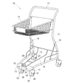
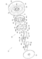
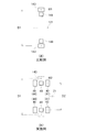
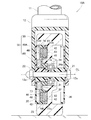
本発明の前提となる参考例1による手動カートの斜視図である。It is a perspective view of the manual cart by the reference example 1 used as the premise of this invention. 図1に示された車輪の縦断面図である。It is a longitudinal cross-sectional view of the wheel shown by FIG. 図2に示された車輪及び発電機の分解斜視図である。FIG. 3 is an exploded perspective view of a wheel and a generator shown in FIG. 2. 図3に示された発電機の組み立て方法について説明する図である。It is a figure explaining the assembly method of the generator shown by FIG. 図3に示された発電機の作用について説明する図である。It is a figure explaining the effect | action of the generator shown by FIG. 本発明の前提となる参考例2による手動カートの斜視図である。It is a perspective view of the manual cart by the reference example 2 used as the premise of this invention. 図6に示された車輪の縦断面図である。It is a longitudinal cross-sectional view of the wheel shown by FIG. 図7に示された車輪及び発電機の分解斜視図である。FIG. 8 is an exploded perspective view of the wheel and the generator shown in FIG. 7. 図7に示された信号送信機の模式図である。FIG. 8 is a schematic diagram of the signal transmitter illustrated in FIG. 7. 図9に示された信号送信機の作用について説明するフロー図である。It is a flowchart explaining the effect | action of the signal transmitter shown by FIG. 本発明の実施例による手動カートに用いられる車輪の縦断面図である。It is a longitudinal cross-sectional view of the wheel used for the manual cart by the Example of this invention. 図11に示された車輪及び発電機の分解斜視図である。FIG. 12 is an exploded perspective view of the wheel and the generator shown in FIG. 11. 変更例による手動カートに用いられる車輪の縦断面図である。It is a longitudinal cross-sectional view of the wheel used for the manual cart by the example of a change. 図13に示された車輪及び発電機の分解斜視図である。FIG. 14 is an exploded perspective view of the wheel and the generator shown in FIG. 13. 従来の技術の基本構成について説明する図である。It is a figure explaining the basic composition of the conventional technology.

本発明の実施の形態の前提となる技術について添付図に基づいて以下に説明する。   The technology that is the premise of the embodiment of the present invention will be described below with reference to the accompanying drawings.

本発明者らは、発電機を有しながらも組立が簡便で、且つ、操作性の高い手動カートの提供を行うべく鋭意研究を重ねた。結果、このような手動カートを少ない部品によって構成することができるようになった。   The present inventors have intensively studied to provide a manual cart that has a generator and is easy to assemble and has high operability. As a result, such a manual cart can be configured with few parts.

以下、本発明の前提である操作性の高い手動カートについて、参考例1及び参考例2に基づいて説明する。その後に、このような手動カートを少ない部品点数によって実現した実施例、及び、変更例について説明する。実施例、及び、変更例による発明の基本的な構成は、参考例による発明と共通している。このため、参考例と共通している部分については、図面の符号を流用し、詳細な説明は省略する。
<参考例1>
Hereinafter, a highly operable manual cart which is a premise of the present invention will be described based on Reference Example 1 and Reference Example 2. Thereafter, an embodiment in which such a manual cart is realized with a small number of parts and a modified example will be described. The basic configuration of the invention according to the embodiment and the modified example is common to the invention according to the reference example. For this reason, about the part which is common in a reference example, the code | symbol of drawing is diverted and detailed description is abbreviate | omitted.
<Reference Example 1>

図1を参照する。図1には、参考例1による手動カート10が示されている。手動カート10は、例えば買い物において用いられる。手動カート10は、金属パイプによって構成された車体11に、車輪支持部材12を介して車輪30が取り付けられてなる。   Please refer to FIG. FIG. 1 shows a manual cart 10 according to the first reference example. The manual cart 10 is used for shopping, for example. The manual cart 10 has wheels 30 attached to a vehicle body 11 formed of metal pipes via a wheel support member 12.

車体11の下部及び上部は、荷物を載置することのできる下部載置部14及び上部載置部15とされている。車体11の後上部に、操作者が把持する把持部17が設けられている。操作者は、把持部17を持って車体11を押すことにより、任意の方向に手動カート10を移動させることができる。   The lower part and the upper part of the vehicle body 11 serve as a lower placing part 14 and an upper placing part 15 on which a load can be placed. A grip portion 17 that is gripped by the operator is provided at the rear upper portion of the vehicle body 11. The operator can move the manual cart 10 in any direction by holding the grip portion 17 and pushing the vehicle body 11.

車輪30には、車輪30が回転することにより発電を行う発電機が内蔵されている。発電機によって発電された電気によって、例えば、車体11に設けられた灯体18を光らせることができる。   The wheel 30 has a built-in generator that generates power when the wheel 30 rotates. For example, the lamp 18 provided on the vehicle body 11 can be illuminated by electricity generated by the generator.

図2を参照する。車輪支持部材12は、車輪30の上方を覆い、断面視において下方に開口する略U字状を呈する。車輪支持部材12の左右の側面部にはボルト挿通孔12a,12aが設けられている。ボルト挿通孔12a,12aにはボルト21が通され、ボルト21の先端にはナット22が取り付けられている。   Please refer to FIG. The wheel support member 12 covers the upper side of the wheel 30 and has a substantially U shape that opens downward in a cross-sectional view. Bolt insertion holes 12 a and 12 a are provided on the left and right side portions of the wheel support member 12. Bolts 21 are passed through the bolt insertion holes 12 a and 12 a, and nuts 22 are attached to the ends of the bolts 21.

車輪30は、ボルト21によって支持され、このボルト21を中心に回転する。即ち、ボルト21は、車輪30の回転中心である車軸ということもできる。   The wheel 30 is supported by a bolt 21 and rotates around the bolt 21. That is, the bolt 21 can also be called an axle that is the center of rotation of the wheel 30.

車輪30は、ボルト21が挿通されたハブ部31と、このハブ部31の外周に一体的に形成された円盤状のディスク部32と、このディスク部32の外周に一体的に設けられたリム部33と、からなる。ハブ部31には、軸受34が設けられている。ハブ部31、軸受34、及び、ディスク部32は、それぞれ車輪30の側方に配置されたカバー部材35,36によって覆われている。   The wheel 30 includes a hub portion 31 through which the bolt 21 is inserted, a disk-shaped disc portion 32 integrally formed on the outer periphery of the hub portion 31, and a rim integrally provided on the outer periphery of the disc portion 32. Part 33. The hub portion 31 is provided with a bearing 34. The hub part 31, the bearing 34, and the disk part 32 are covered with cover members 35 and 36 disposed on the sides of the wheel 30, respectively.

これらの、車輪30の側面と、カバー部材35とによって囲われた領域に発電機40が収納されている。   The generator 40 is housed in a region surrounded by the side surface of the wheel 30 and the cover member 35.

図3を併せて参照する。発電機40は、車輪30の側面に沿って設けられ車輪30と共に回転する第1のプレート41と、この第1のプレート41によって保持された第1の金属板42と、これらの第1の金属板42にそれぞれ固定された第1の永久磁石43(永久磁石43)と、車輪30の側面に対向して設けられ第1のプレート41と共に回転する第2のプレート44と、この第2のプレート44によって保持された第2の金属板45(金属板45)と、これらの第2の金属板45にそれぞれ固定された第2の永久磁石46と、ボルト21に設けられたコイルホルダ47と、このコイルホルダ47によって保持され第1のプレート41及び第2のプレート44の間に位置するコイル48と、を有している。コイルホルダ47には、制御基板49が固定されている。   Please refer to FIG. The generator 40 includes a first plate 41 provided along the side surface of the wheel 30 and rotating together with the wheel 30, a first metal plate 42 held by the first plate 41, and these first metals. A first permanent magnet 43 (permanent magnet 43) fixed to each of the plates 42, a second plate 44 that faces the side surface of the wheel 30 and rotates together with the first plate 41, and the second plate A second metal plate 45 (metal plate 45) held by 44, a second permanent magnet 46 fixed to each of these second metal plates 45, a coil holder 47 provided on the bolt 21, A coil 48 held by the coil holder 47 and positioned between the first plate 41 and the second plate 44. A control board 49 is fixed to the coil holder 47.

第1のプレート41は、中央に円形の穴が開いたドーナツ形状の板材である。第1のプレート41の素材は、例えば、樹脂からなる。第1のプレート41の中央の穴の縁に沿って、第2のプレート44に向かって突出する突出部41aが設けられている。第1のプレート41は、第1の永久磁石43を嵌め込むための磁石嵌め込み穴41bを有している。   The first plate 41 is a donut-shaped plate having a circular hole in the center. The material of the first plate 41 is made of resin, for example. A protrusion 41 a that protrudes toward the second plate 44 is provided along the edge of the central hole of the first plate 41. The first plate 41 has a magnet fitting hole 41 b for fitting the first permanent magnet 43.

これらの磁石嵌め込み穴41bは、車輪側に設けられた金属製の第1の金属板42,42によって、一端が塞がれている。第1の金属板42は、第1のプレート41に接着されている。第1の永久磁石43は、第1の金属板42,42に、第1の永久磁石43の磁力により吸着している。即ち、第1の金属板42,42は、磁性を有する。第1の金属板42,42は、軟鉄板で構成されている。   One end of each of the magnet fitting holes 41b is closed by metal first metal plates 42 and 42 provided on the wheel side. The first metal plate 42 is bonded to the first plate 41. The first permanent magnet 43 is attracted to the first metal plates 42 and 42 by the magnetic force of the first permanent magnet 43. That is, the first metal plates 42 and 42 have magnetism. The 1st metal plates 42 and 42 are comprised with the soft iron plate.

突出部41aは、先端に第2のプレート44に向かって突出する位置決めピン41cが設けられている。突出部41aの先端に第2のプレート44は、載せられる。即ち、突出部41aは、第1のプレート41と、第2のプレート44との間に所定の隙間を確保するスペーサということができる。突出部41a、即ち、スペーサは、第1のプレート41に一体的に形成されている。なお、スペーサは、第2のプレート44に一体的に形成されていてもよい。   The protruding portion 41 a is provided with a positioning pin 41 c that protrudes toward the second plate 44 at the tip. The second plate 44 is placed on the tip of the protrusion 41a. That is, the protruding portion 41 a can be referred to as a spacer that secures a predetermined gap between the first plate 41 and the second plate 44. The protrusion 41 a, that is, the spacer is formed integrally with the first plate 41. The spacer may be formed integrally with the second plate 44.

第1の永久磁石43は、丸型の永久磁石が採用されている。複数の第1の永久磁石43は、それぞれがボルト21から同じ距離の位置に円弧状に並べて配置されている。第1の永久磁石43は、第2の永久磁石46から見て、正極(N極)と負極(S極)とが交互に並ぶよう、配置されている。   The first permanent magnet 43 is a round permanent magnet. The plurality of first permanent magnets 43 are arranged in a circular arc shape at the same distance from the bolt 21. The first permanent magnets 43 are arranged so that the positive electrode (N pole) and the negative electrode (S pole) are alternately arranged when viewed from the second permanent magnet 46.

第2のプレート44は、中央に円形の穴が開いたドーナツ形状の板材をベースとし、長円形状に切り欠いた欠肉部44a,44aが中心を挟んで2カ所に設けられている。欠肉部44a,44aは、第2のプレート44の周縁に形成され、略C字状を呈している。第2のプレート44の素材は、例えば、樹脂からなる。第2のプレート44は、第2の永久磁石46を嵌め込むための磁石嵌め込み穴44bを有している。   The second plate 44 is based on a donut-shaped plate material having a circular hole in the center, and is provided with two thin portions 44a, 44a cut out in an oval shape with the center in between. The lacking portions 44a and 44a are formed on the periphery of the second plate 44 and have a substantially C-shape. The material of the second plate 44 is made of resin, for example. The second plate 44 has a magnet fitting hole 44 b for fitting the second permanent magnet 46.

これらの磁石嵌め込み穴44bは、カバー部材35側に設けられた金属製の第2の金属板45によって、一端が塞がれている。第2の金属板45は、第2のプレート44に接着されている。第2の永久磁石46は、第2の金属板45に、第2の永久磁石46の磁力により吸着している。即ち、第2の金属板45,45は、磁性を有する。第2の金属板45,45は、軟鉄板で構成されている。第2のプレート44は、位置決めピン41cが差し込まれる位置決め穴44c,44cを有している。   One end of each of the magnet fitting holes 44b is closed by a metal second metal plate 45 provided on the cover member 35 side. The second metal plate 45 is bonded to the second plate 44. The second permanent magnet 46 is attracted to the second metal plate 45 by the magnetic force of the second permanent magnet 46. That is, the second metal plates 45, 45 have magnetism. The 2nd metal plates 45 and 45 are comprised with the soft iron plate. The second plate 44 has positioning holes 44c and 44c into which the positioning pins 41c are inserted.

第2の永久磁石46は、丸型の永久磁石が採用されている。複数の第2の永久磁石46は、それぞれがボルト21から同じ距離の位置に円弧状に並べて配置されている。第2の永久磁石46は、第1の永久磁石43から見て、正極(N極)と負極(S極)とが交互に並ぶよう、配置されている。   The second permanent magnet 46 is a round permanent magnet. The plurality of second permanent magnets 46 are arranged in a circular arc shape at the same distance from the bolt 21. The second permanent magnet 46 is arranged so that the positive electrode (N pole) and the negative electrode (S pole) are alternately arranged when viewed from the first permanent magnet 43.

第2の永久磁石46は、それぞれ、第1の永久磁石43に対向して配置されている。それぞれ対向して配置された第1の永久磁石43、及び、第2の永久磁石46は、一方が正極であると、他方は負極となるごとく、異なる極が対向して配置されている。   The second permanent magnets 46 are respectively disposed to face the first permanent magnets 43. The first permanent magnet 43 and the second permanent magnet 46 arranged to face each other are arranged so that different poles face each other so that when one is a positive electrode, the other is a negative electrode.

なお、位置決めピン41cと、位置決め穴44c,44cとは、これらが逆であってもよい。即ち、第1のプレート41に位置決め穴が設けられ、第2のプレートに位置決めピンが設けられていてもよい。つまり、第1のプレート41に対して、第2のプレート44を位置決めすることができればよい。第1のプレート41に対して、第2のプレート44が位置決めされることにより、第1の永久磁石43は、第2の永久磁石46に対向して設けられる。   The positioning pins 41c and the positioning holes 44c and 44c may be reversed. That is, the first plate 41 may be provided with a positioning hole, and the second plate may be provided with a positioning pin. That is, it is only necessary that the second plate 44 can be positioned with respect to the first plate 41. By positioning the second plate 44 with respect to the first plate 41, the first permanent magnet 43 is provided to face the second permanent magnet 46.

コイルホルダ47は、例えば、一体成形された樹脂によって形成されている。コイルホルダ47は、ボルト21を通すことができるボス部47aと、このボス部47aのカバー部材35側の端部から延びる略U字状のアーム部47bと、このアーム部47bの先端にそれぞれ設けられコイル48,48を保持するコイル保持部47c,47cと、アーム部47bの中央からカバー部材35に向かって突出する位置決めピン47dと、からなる。アーム部47bの先端は、第2のプレート44に向かっている。   The coil holder 47 is made of, for example, an integrally molded resin. The coil holder 47 is provided at a boss portion 47a through which the bolt 21 can pass, a substantially U-shaped arm portion 47b extending from an end portion of the boss portion 47a on the cover member 35 side, and a tip of the arm portion 47b. Coil holding portions 47c and 47c for holding the coils 48 and 48, and positioning pins 47d protruding toward the cover member 35 from the center of the arm portion 47b. The tip of the arm portion 47 b faces the second plate 44.

コイルホルダ47は、軸受34の内輪部34aに当接するように配置される。コイルホルダ47は、カバー部材35と、車輪支持部材12を介してボルト21とナット22とで内輪部34aに取り付けられる。車輪30は、回転軸であるボルト21に対して自在に回転可能なように構成されている。車輪30が回転しても軸受34の内輪部34aは回転しない。従って、内輪部34aとボルト21とで挟まれたコイルホルダ47も、車輪30の回転に関係なく、固定位置を保持したままとなる。   The coil holder 47 is disposed so as to contact the inner ring portion 34 a of the bearing 34. The coil holder 47 is attached to the inner ring portion 34 a with the bolt 21 and the nut 22 via the cover member 35 and the wheel support member 12. The wheel 30 is configured to be freely rotatable with respect to the bolt 21 that is a rotating shaft. Even if the wheel 30 rotates, the inner ring portion 34a of the bearing 34 does not rotate. Therefore, the coil holder 47 sandwiched between the inner ring portion 34a and the bolt 21 also maintains the fixed position regardless of the rotation of the wheel 30.

コイル保持部47c,47cは、共に長円形状を呈する。コイル保持部47c,47cの形状は、欠肉部44a,44aの形状に略一致している。コイル保持部47c,47cの大きさは、欠肉部44a,44aの大きさよりも僅かに小さい。   The coil holding portions 47c and 47c both have an oval shape. The shape of the coil holding portions 47c and 47c substantially matches the shape of the lacking portions 44a and 44a. The size of the coil holding portions 47c and 47c is slightly smaller than the size of the lacking portions 44a and 44a.

コイル48,48は、銅線を巻いて形成され、それぞれコイル保持部47c,47cに保持されている。コイル48,48は第1の永久磁石43と第2の永久磁石46とによって挟まれる。   The coils 48 and 48 are formed by winding a copper wire and are held by coil holding portions 47c and 47c, respectively. The coils 48 are sandwiched between the first permanent magnet 43 and the second permanent magnet 46.

制御基板49、及び、カバー部材35には、それぞれ位置決め穴49a,35aが設けられている。コイルホルダ47に設けられた位置決めピン47dは、制御基板49の位置決め穴49aを貫通し、カバー部材35の位置決め穴35aまで達している。   Positioning holes 49a and 35a are provided in the control board 49 and the cover member 35, respectively. Positioning pins 47 d provided on the coil holder 47 pass through the positioning holes 49 a of the control board 49 and reach the positioning holes 35 a of the cover member 35.

なお、これらの位置決めピン47dと、位置決め穴49a,35aとは、適宜入れ替えることができる。即ち、制御基板49にコイル保持部47cに向かって突出すると共にカバー部材35に向かって突出する位置決めピンを設けることもできる。さらには、カバー部材35にコイル保持部47cに向かって突出する位置決めピンを設けることもできる。コイル保持部47c、制御基板49、カバー部材35を互いに位置決めすることができればよい。   The positioning pins 47d and the positioning holes 49a and 35a can be appropriately replaced. In other words, the control board 49 may be provided with a positioning pin that protrudes toward the coil holding portion 47 c and protrudes toward the cover member 35. Furthermore, a positioning pin that protrudes toward the coil holding portion 47 c can be provided on the cover member 35. It is only necessary that the coil holding portion 47c, the control board 49, and the cover member 35 can be positioned with respect to each other.

図4を参照する。図4には、上から第1のプレート41、第2の永久磁石46が固定された第2のプレート44、コイルホルダ47、及びコイル48が示されている。説明の便宜上、第2のプレート44は、第2の金属板45が取り外された状態で示されている。また、コイルホルダ47は、左の一部が部分断面によって示されている。   Please refer to FIG. FIG. 4 shows the first plate 41, the second plate 44 to which the second permanent magnet 46 is fixed, the coil holder 47, and the coil 48 from above. For convenience of explanation, the second plate 44 is shown with the second metal plate 45 removed. The coil holder 47 is partially shown on the left by a partial cross section.

発電機40を組み立てる際には、矢印(1)によって示されるように、第2のプレート44を第1のプレート41に重ね合わせる。第1のプレート41には、位置決めピン41c,41cが設けられ、第2のプレート44には、位置決め穴44c,44cが設けられている。位置決め穴44c,44cに位置決めピン41c,41cが挿入されるよう第2のプレート44を第1のプレート41に重ね合わせる。これにより、第1のプレート41に対して、正確な位置に第2のプレート44を配置することができる。   When assembling the generator 40, the second plate 44 is superposed on the first plate 41 as indicated by the arrow (1). The first plate 41 is provided with positioning pins 41c and 41c, and the second plate 44 is provided with positioning holes 44c and 44c. The second plate 44 is overlaid on the first plate 41 so that the positioning pins 41c, 41c are inserted into the positioning holes 44c, 44c. Thereby, the second plate 44 can be arranged at an accurate position with respect to the first plate 41.

第2のプレート44を正確な位置に配置することにより、第1の永久磁石43のそれぞれに対向して第2の永久磁石46が配置される。第1の永久磁石43の第2の永久磁石46に対向する面が正極(N極)であるとき、第2の永久磁石46の第1の永久磁石43に対向する面は、負極(S極)とされている。   By arranging the second plate 44 at an accurate position, the second permanent magnets 46 are arranged to face the first permanent magnets 43, respectively. When the surface of the first permanent magnet 43 that faces the second permanent magnet 46 is the positive electrode (N pole), the surface of the second permanent magnet 46 that faces the first permanent magnet 43 is the negative electrode (S pole). ).

図に示される状態において、第2の永久磁石46は、第1の永久磁石43に対向する面の裏面が示されている。このため、図に示される状態において、対応する第1の永久磁石43と第2の永久磁石46との極は、同極となる。   In the state shown in the drawing, the back surface of the second permanent magnet 46 facing the first permanent magnet 43 is shown. For this reason, in the state shown in the figure, the corresponding poles of the first permanent magnet 43 and the second permanent magnet 46 are the same pole.

次に、矢印(2)によって示されるように、コイルホルダ47を第2のプレート44に重ね合わせる。重ね合わせる際に、コイル保持部47c,47cを欠肉部44a,44aから、第1のプレート41と第2のプレート44との間に臨ませる。   Next, the coil holder 47 is overlaid on the second plate 44 as indicated by the arrow (2). When superimposing, the coil holding portions 47c and 47c are caused to face between the first plate 41 and the second plate 44 from the lacking portions 44a and 44a.

図2を参照する。車体11(図1参照)を押して移動することにより、車輪30が回転する。車輪30が回転すると、車輪30と共に第1のプレート41、第1の永久磁石43、第2のプレート44、及び、第2の永久磁石46が回転する。   Please refer to FIG. The wheel 30 rotates by pushing and moving the vehicle body 11 (see FIG. 1). When the wheel 30 rotates, the first plate 41, the first permanent magnet 43, the second plate 44, and the second permanent magnet 46 rotate together with the wheel 30.

一方、ボルト21、ナット22、コイルホルダ47、コイル48、制御基板49、カバー部材35,36は、回転しない。   On the other hand, the bolt 21, the nut 22, the coil holder 47, the coil 48, the control board 49, and the cover members 35 and 36 do not rotate.

第1の永久磁石43、及び、第2の永久磁石46が回転すると、図2に示されるように、瞬間的にコイル48を挟んだ状態となる。即ち、コイル48,48は、第1の永久磁石43と第2の永久磁石46との間に位置する。さらに、車輪30が回転して第1の永久磁石43、及び、第2の永久磁石46が回転すると、コイル48を貫通する磁束が変化する。電磁誘導によりコイル48に起電力が生じ、誘導電流が発生する。   When the first permanent magnet 43 and the second permanent magnet 46 are rotated, as shown in FIG. 2, the coil 48 is sandwiched instantaneously. That is, the coils 48 are positioned between the first permanent magnet 43 and the second permanent magnet 46. Furthermore, when the wheel 30 rotates and the first permanent magnet 43 and the second permanent magnet 46 rotate, the magnetic flux penetrating the coil 48 changes. An electromotive force is generated in the coil 48 by electromagnetic induction, and an induced current is generated.

以上の構成から、以下の効果を得ることができる。   From the above configuration, the following effects can be obtained.

ボルト21が延びている方向に沿って第1の永久磁石43、及び、第2の永久磁石46が設けられ、これらの間にコイル48が配置されている。本発明の構成では、コイル48を貫く磁束を変化させるための負荷が発生しない。このため、手動カート10の操作荷重はほとんど増加しない。即ち、発電機40を有しながらも操作性の高い手動カート10を提供できる。また、車輪30を組み立てる際に、車体11を必要としない。このため、車輪30のみを組み立てた上で、車体11に車輪30を取り付けることができる。このため、組立作業が簡便である。   The 1st permanent magnet 43 and the 2nd permanent magnet 46 are provided along the direction where the volt | bolt 21 is extended, The coil 48 is arrange | positioned among these. In the configuration of the present invention, a load for changing the magnetic flux passing through the coil 48 is not generated. For this reason, the operation load of the manual cart 10 hardly increases. That is, it is possible to provide the manual cart 10 with high operability while having the generator 40. Further, when assembling the wheels 30, the vehicle body 11 is not required. For this reason, the wheel 30 can be attached to the vehicle body 11 after assembling only the wheel 30. For this reason, the assembling work is simple.

操作性を高めることができる理由は、以下のようにも説明することができる。図5(a)、及び、図5(b)を参照する。図5(a)には、実施例と比較するための比較例による発電構造が簡略化して示されている。図5(b)には、実施例による発電構造が簡略化して示されている。また、図5(b)には、図5(a)の比較例を2点鎖線で示している。比較例におけるボルト121の中心からコイル148までの距離、及び、実施例におけるボルト21の中心からコイル48までの距離は略同一となっている。このため、図5(b)は、比較例におけるボルト121、及び、コイル148を示すことなく、コイル48(148)と第1の永久磁石143の位置関係が理解できるように、比較例の第1の永久磁石143のみを2点鎖線で示している。   The reason why the operability can be improved can also be explained as follows. Reference is made to FIG. 5A and FIG. FIG. 5A shows a simplified power generation structure according to a comparative example for comparison with the embodiment. FIG. 5B shows a simplified power generation structure according to the embodiment. FIG. 5B shows a comparative example of FIG. 5A with a two-dot chain line. The distance from the center of the bolt 121 in the comparative example to the coil 148 and the distance from the center of the bolt 21 in the embodiment to the coil 48 are substantially the same. For this reason, FIG. 5B shows the first example of the comparative example so that the positional relationship between the coil 48 (148) and the first permanent magnet 143 can be understood without showing the bolt 121 and the coil 148 in the comparative example. Only one permanent magnet 143 is indicated by a two-dot chain line.

図5(a)の比較例において、ボルト121の中心から第1の永久磁石143の重心までの距離の2倍をD1とする。そして、第1の永久磁石143の質量をW1とする。この第1の永久磁石143の慣性力は、W1・D12に比例する。D1が大きいほど、慣性力が大きくなり、加減速時に大きな力が必要となるため、始動時に要する押力は、大きくなる。 In the comparative example of FIG. 5A, D1 is twice the distance from the center of the bolt 121 to the center of gravity of the first permanent magnet 143. And let the mass of the 1st permanent magnet 143 be W1. Inertia force of the first permanent magnet 143 is proportional to W1 · D1 2. As D1 increases, the inertial force increases, and a large force is required during acceleration / deceleration. Therefore, the pressing force required at the time of starting increases.

本発明においては、図5(b)の実施例に示すように、ボルト21の中心から第1の永久磁石43の重心までの距離の2倍がD2である。第1の永久磁石43の質量をW2とすると、始動時に要する押力は、W2・D22に比例することとなる。 In the present invention, as shown in the embodiment of FIG. 5B, twice the distance from the center of the bolt 21 to the center of gravity of the first permanent magnet 43 is D2. When the mass of the first permanent magnet 43 and W2, pushing force required during startup, and thus proportional to W2 · D2 2.

図5(b)に示すように、実施例における第1の永久磁石43は、ボルト21の中心に対して、コイル48と略同じ位置に設けられる。それに対して、比較例における第1の永久磁石143(図5(b)の二点鎖線を参照)はコイル48の外周に設けられている。比較例におけるボルト121の中心からコイル148までの距離、及び、実施例におけるボルト21の中心からコイル48までの距離は略同一であるため、図5(b)に示すようにD1>D2の関係となっている。一方、第1の永久磁石43の重量W2は、従来と同じ質量のものを採用することができる。即ち、W1=W2である。このため、W1・D12>W2・D22とすることができる。即ち、本発明による手動カート10は、始動時に必要な押力が小さく済み、高い操作性を有すると言える。 As shown in FIG. 5B, the first permanent magnet 43 in the embodiment is provided at substantially the same position as the coil 48 with respect to the center of the bolt 21. On the other hand, the first permanent magnet 143 (see the two-dot chain line in FIG. 5B) in the comparative example is provided on the outer periphery of the coil 48. Since the distance from the center of the bolt 121 in the comparative example to the coil 148 and the distance from the center of the bolt 21 in the embodiment to the coil 48 are substantially the same, the relationship of D1> D2 as shown in FIG. 5B. It has become. On the other hand, the weight of the first permanent magnet 43 can be the same as that of the conventional magnet. That is, W1 = W2. Therefore, W1 · D1 2 > W2 · D2 2 can be satisfied. That is, it can be said that the manual cart 10 according to the present invention requires a small pressing force at the time of starting and has high operability.

図5(b)を参照する。第1の永久磁石43(第1のプレート41)、コイル48、及び、第2の永久磁石46(第2のプレート44)は、ボルト21の軸方向に沿って配置されている。二点鎖線で示すように、ボルト121(ボルト21)を中心として、コイル148(コイル48)の外周に第1の永久磁石143を配置した場合に比べ、実施例は、車輪30の周方向に発電機40をコンパクトにすることができる(即ち、D1>D2)。このため、より小さな車輪30であっても発電機40を取り付けることができる。設計の自由度を高めることができる。   Reference is made to FIG. The first permanent magnet 43 (first plate 41), the coil 48, and the second permanent magnet 46 (second plate 44) are disposed along the axial direction of the bolt 21. As shown by a two-dot chain line, the embodiment is arranged in the circumferential direction of the wheel 30 as compared with the case where the first permanent magnet 143 is arranged on the outer periphery of the coil 148 (coil 48) around the bolt 121 (bolt 21). The generator 40 can be made compact (ie, D1> D2). For this reason, even if it is a smaller wheel 30, the generator 40 can be attached. The degree of design freedom can be increased.

図3を参照する。第2のプレート44は、コイル保持部47cの形状に沿って欠肉状に形成された欠肉部44aを有している。この欠肉部44aから第1の永久磁石43、及び、第2の永久磁石46の間にコイル48を臨ませることができる。発電機40の小型化を図ることができる。   Please refer to FIG. The second plate 44 has a thinned portion 44a formed in a thin shape along the shape of the coil holding portion 47c. The coil 48 can be faced between the first permanent magnet 43 and the second permanent magnet 46 from the thinned portion 44a. The generator 40 can be miniaturized.

第1の永久磁石43、及び、第2の永久磁石46は、第1のプレート41の正面視を基準として、正極及び負極が交互に並べられている。これにより、効率よく発電を行うことができる。
<参考例2>
In the first permanent magnet 43 and the second permanent magnet 46, positive and negative electrodes are alternately arranged with reference to the front view of the first plate 41. Thereby, electric power generation can be performed efficiently.
<Reference Example 2>

次に、本発明の前提となる参考例2による発明を図面に基づいて説明する。   Next, the invention according to Reference Example 2 which is the premise of the present invention will be described with reference to the drawings.

図6を参照する。図6には、参考例2による手動カート10Aが示されている。手動カート10Aは、店舗内に複数配置され、それぞれ別の操作者によって操作される。手動カート10Aは、手動カート用信号発信装置50を含む。手動カート用信号発信装置50は、手動カート10Aが走行すると、手動カート10A毎に割り振られたID番号を送信する。手動カート10Aが走行する店舗内には、複数の受信装置が配置されている。どの受信装置が送信信号を受信したかによって、手動カート10の走行経路を調べることができる。   Please refer to FIG. FIG. 6 shows a manual cart 10A according to the second reference example. A plurality of manual carts 10A are arranged in the store and are operated by different operators. The manual cart 10 </ b> A includes a manual cart signal transmission device 50. When the manual cart 10A travels, the manual cart signal transmission device 50 transmits an ID number assigned to each manual cart 10A. A plurality of receiving devices are arranged in the store where the manual cart 10A travels. Depending on which receiving device has received the transmission signal, the travel route of the manual cart 10 can be examined.

図7及び図8を参照する。参考例2による手動カート10Aの発電機40Aは、参考例1に用いた発電機40(図2参照)に対して、コイルホルダ77、及び、第2のプレート74の形状が変更されている。   Please refer to FIG. 7 and FIG. In the generator 40A of the manual cart 10A according to the reference example 2, the shapes of the coil holder 77 and the second plate 74 are changed with respect to the generator 40 (see FIG. 2) used in the reference example 1.

その他の基本的な構成については、参考例1による手動カート10と共通する。参考例1と共通する部分については、符号を流用すると共に、詳細な説明を省略する。   Other basic configurations are common to the manual cart 10 according to the first reference example. About the part which is common in the reference example 1, while using a code | symbol, detailed description is abbreviate | omitted.

手動カート用信号発信装置50は、車輪30と、この車輪30に設けられ車輪30が回転することにより発電する発電機40Aと、この発電機40Aが発電した電気により信号を発信する信号送信機60と、を有する。   The manual cart signal transmission device 50 includes a wheel 30, a generator 40 </ b> A that is provided on the wheel 30 and generates power when the wheel 30 rotates, and a signal transmitter 60 that transmits a signal by electricity generated by the generator 40 </ b> A. And having.

電磁誘導式の発電機40A、及び、信号送信機60は、ディスク部32、及び、リム部33によって凹状に形成された部位に収納されている。   The electromagnetic induction generator 40 </ b> A and the signal transmitter 60 are accommodated in a portion formed in a concave shape by the disk portion 32 and the rim portion 33.

信号送信機60は、コイルホルダ77の外側の面に配置され、発電機40が発電した電気により信号を発信する。   The signal transmitter 60 is disposed on the outer surface of the coil holder 77 and transmits a signal by electricity generated by the generator 40.

第2のプレート74は、第1のプレート41に対向した略円盤状の第2プレート本体部74aと、この第2プレート本体部74aの周縁から第1のプレート41の周縁に向かって延びる第2プレート壁部74bと、からなる。   The second plate 74 has a substantially disk-shaped second plate main body portion 74 a facing the first plate 41, and a second plate 74 extending from the peripheral edge of the second plate main body portion 74 a toward the peripheral edge of the first plate 41. Plate wall 74b.

第2プレート本体部74aは、中央に円形の穴74cが開いたドーナツ形状の板材をベースとし、円形の穴から周方向外方に向かってさらに正方形状に切り欠いた欠肉部74d,74dが2カ所に設けられている。欠肉部74d,74dは、第2プレート本体部74aの中心を挟むように2カ所に形成されている。第2のプレート74の素材は、例えば、樹脂からなる。第2のプレート74は、第2の永久磁石46を嵌め込むための磁石嵌め込み穴74fを有している。これらの磁石嵌め込み穴74fは、カバー部材35側に設けられた金属製の第2の金属板45,45によって、一端が塞がれている。第2の金属板45は、第2プレート本体部74aに接着されている。   The second plate main body 74a is based on a donut-shaped plate material having a circular hole 74c in the center. There are two places. The thinned portions 74d and 74d are formed at two locations so as to sandwich the center of the second plate main body portion 74a. The material of the second plate 74 is made of resin, for example. The second plate 74 has a magnet fitting hole 74 f for fitting the second permanent magnet 46. One end of each of the magnet insertion holes 74f is closed by a metal second metal plate 45, 45 provided on the cover member 35 side. The second metal plate 45 is bonded to the second plate body 74a.

第2プレート壁部74bは、第2プレート本体部74aの周縁に亘って円環状に形成されている。第2プレート壁部74bによって、第2プレート本体部74aは、第1のプレート41に対して所定の距離を保った状態において対向している。即ち、第2プレート壁部74bは、スペーサの役割を果たしている。第2プレート壁部74bは、位置決めピン41cが差し込まれる位置決め穴74eを有している。   The 2nd plate wall part 74b is formed in the annular | circular shape over the periphery of the 2nd plate main-body part 74a. Due to the second plate wall 74b, the second plate main body 74a is opposed to the first plate 41 in a state where a predetermined distance is maintained. That is, the second plate wall 74b plays a role of a spacer. The second plate wall 74b has a positioning hole 74e into which the positioning pin 41c is inserted.

なお、第1のプレート41に第2のプレート74に向かって立ち上げられた壁部を形成し、これをスペーサとしてもよい。   Note that a wall portion raised toward the second plate 74 may be formed on the first plate 41, and this may be used as a spacer.

さらに、位置決めピン41cと、位置決め穴74eとは、これらが逆であってもよい。即ち、第1のプレート41に位置決め穴が設けられ、第2のプレートに位置決めピンが設けられていてもよい。つまり、第1のプレート41に対して、第2のプレート74を位置決めすることができればよい。これにより、永久磁石43に対向した位置に、第2の金属板45を位置決めできる。   Further, the positioning pin 41c and the positioning hole 74e may be reversed. That is, the first plate 41 may be provided with a positioning hole, and the second plate may be provided with a positioning pin. That is, it is only necessary that the second plate 74 can be positioned with respect to the first plate 41. Thereby, the second metal plate 45 can be positioned at a position facing the permanent magnet 43.

コイルホルダ77は、例えば、一体成形された樹脂によって形成されている。コイルホルダ77は、ボルト21を通すことができるドーナツ板状のボス部77aと、このボス部77aから外周に向かって延びコイル48,48を保持するコイル保持部77c,77cと、からなる。   The coil holder 77 is made of, for example, an integrally molded resin. The coil holder 77 includes a donut plate-like boss portion 77 a through which the bolt 21 can pass, and coil holding portions 77 c and 77 c that extend from the boss portion 77 a toward the outer periphery and hold the coils 48 and 48.

コイル保持部77c,77cは、共に略正方形状を呈する。コイル保持部77c,77cの形状は、欠肉部74d,74dの形状に略一致している。コイル保持部77c,77cの大きさは、欠肉部74d,74dの大きさよりも僅かに小さい。   The coil holding portions 77c and 77c both have a substantially square shape. The shapes of the coil holding portions 77c and 77c substantially match the shapes of the lacking portions 74d and 74d. The size of the coil holding portions 77c and 77c is slightly smaller than the size of the lacking portions 74d and 74d.

なお、カバー部材35に、コイル保持部77cに向かって突出する位置決めピンを設けることもできる。コイル保持部77c、信号送信機60、カバー部材35を互いに位置決めすることができればより好ましい。   The cover member 35 may be provided with a positioning pin that protrudes toward the coil holding portion 77c. It is more preferable if the coil holding part 77c, the signal transmitter 60, and the cover member 35 can be positioned with respect to each other.

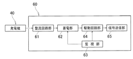
図9を参照する。信号送信機60は、発電機40により発電された交流電力を直流電力に変換する整流回路部61と、この整流回路部61において整流された電力を蓄電する蓄電部62と、この蓄電部62に蓄電された電力量を監視する監視部63と、この監視部63の監視している電力量が所定の電力量に到達した際に後段回路を駆動する信号をだす駆動回路部64と、この駆動回路部64からの駆動信号により個別識別番号(ID番号)を送信する信号送信部65と、を有している。   Please refer to FIG. The signal transmitter 60 includes a rectifier circuit unit 61 that converts AC power generated by the generator 40 into DC power, a power storage unit 62 that stores the power rectified in the rectifier circuit unit 61, and a power storage unit 62. A monitoring unit 63 that monitors the amount of stored electric power, a drive circuit unit 64 that outputs a signal for driving a subsequent circuit when the amount of power monitored by the monitoring unit 63 reaches a predetermined amount of power, and this driving And a signal transmission unit 65 that transmits an individual identification number (ID number) by a drive signal from the circuit unit 64.

図7を参照する。信号送信機60は車輪30の回転軸となるボルト21を回避するように、ドーナツ状に構成されている。信号送信機60は、コイル48と電気的に接続されていることから、コイル48に対して信号送信機60が回転するようなことが起こると、信号送信機60とコイル48の電気的な接続が断線してしまい、発生した電力を取り出せなくなってしまう。従って、信号送信機60はコイルホルダ77に対して固定されることが好ましい。信号送信機60を固定しない場合にはスリップリング等の追加の接続端子などが必要となり、信号送信機60やコイルホルダ77が大きくなる傾向にある。   Please refer to FIG. The signal transmitter 60 is configured in a donut shape so as to avoid the bolt 21 that serves as the rotating shaft of the wheel 30. Since the signal transmitter 60 is electrically connected to the coil 48, when the signal transmitter 60 rotates with respect to the coil 48, the electrical connection between the signal transmitter 60 and the coil 48 is performed. Is disconnected, and the generated power cannot be taken out. Therefore, the signal transmitter 60 is preferably fixed to the coil holder 77. When the signal transmitter 60 is not fixed, an additional connection terminal such as a slip ring is required, and the signal transmitter 60 and the coil holder 77 tend to be large.

以下に、手動カート用信号発信装置50の作用について説明する。   Below, the effect | action of the signal transmission apparatus 50 for manual carts is demonstrated.

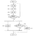
図9及び図10を参照する。車輪30が回転することにより発電がされる(ステップ01。以下、ステップを「ST」と略記する。)。発電された電気は、整流回路部61において、交流から直流に変換される(ST02)。変換された電気は、蓄電部62に蓄電される(ST03)。監視部63は、蓄電量が所定の量に達したかを監視する(ST04)。所定値未満である場合には、ST01に戻る。   Please refer to FIG. 9 and FIG. Electricity is generated by the rotation of the wheel 30 (step 01. Hereinafter, step is abbreviated as “ST”). The generated electricity is converted from alternating current to direct current in the rectifying circuit unit 61 (ST02). The converted electricity is stored in the power storage unit 62 (ST03). Monitoring unit 63 monitors whether the amount of stored electricity has reached a predetermined amount (ST04). If it is less than the predetermined value, the process returns to ST01.

蓄電量が所定値以上となった場合には、駆動回路部64は、ID番号を送信するよう信号送信部65を作動させる(ST05)。このとき、蓄電部62に蓄電された電力が大きすぎると、蓄電部62、駆動回路部64および信号送信部65に負荷が加わる。そのため、監視部63は、駆動回路部64を駆動させるための電圧が所定値未満であることを監視する(ST06)。信号送信部65が作動中に、電圧が所定値以上になった場合は、監視部63に設けられた保護回路で電圧を抑制する(ST07)。この保護動作により、蓄電部62、駆動回路部64および信号送信部65が、過電圧により大きな負荷が加わることを防止することができる。   When the charged amount is equal to or greater than the predetermined value, the drive circuit unit 64 operates the signal transmission unit 65 to transmit the ID number (ST05). At this time, if the power stored in power storage unit 62 is too large, a load is applied to power storage unit 62, drive circuit unit 64, and signal transmission unit 65. Therefore, the monitoring unit 63 monitors that the voltage for driving the drive circuit unit 64 is less than a predetermined value (ST06). When the voltage becomes a predetermined value or more while the signal transmission unit 65 is in operation, the voltage is suppressed by a protection circuit provided in the monitoring unit 63 (ST07). By this protection operation, the power storage unit 62, the drive circuit unit 64, and the signal transmission unit 65 can prevent a large load from being applied due to overvoltage.

なお、誘導起電力は、第1の永久磁石43と第2の永久磁石46の磁束密度、及び、面積、コイル48の巻き数、及び、抵抗によって調節することができる。   The induced electromotive force can be adjusted by the magnetic flux density and area of the first permanent magnet 43 and the second permanent magnet 46, the number of turns of the coil 48, and the resistance.

図6及び図7を参照して、以上を簡単に纏める。手動カート10を走行させて車輪30を回転させることにより、信号送信機60に電気が蓄電される。走行距離が概ね所定量に達すると、蓄電量が所定量に達する。この所定量は、ID番号を送信するのに必要な電力量と言うこともできる。蓄電量が所定量に達すると、信号送信機60は、ID番号を送信する。手動カート10が走行する店舗内には、複数の受信装置が配置されている。手動カート10が走行し、信号送信機60のID番号を送信する位置が変わることにより、ID番号を受信する受信装置が変更される。どの受信装置において受信されたかを記録することにより、手動カート10の走行経路を把握することができる。   The above is briefly summarized with reference to FIGS. Electricity is stored in the signal transmitter 60 by running the manual cart 10 and rotating the wheels 30. When the travel distance reaches a predetermined amount, the storage amount reaches a predetermined amount. This predetermined amount can be said to be the amount of power required to transmit the ID number. When the storage amount reaches a predetermined amount, the signal transmitter 60 transmits an ID number. In the store where the manual cart 10 travels, a plurality of receiving devices are arranged. When the manual cart 10 travels and the position where the ID number of the signal transmitter 60 is transmitted changes, the receiving device that receives the ID number is changed. By recording which receiving device has received the information, the travel route of the manual cart 10 can be grasped.

以上の構成により、さらに以下の効果を得ることができる。   With the above configuration, the following effects can be further obtained.

図8を参照する。欠肉部74dは、ドーナツ板状の中央の円形の穴74cから連続して形成されている。この欠肉部74dから第1のプレート41と第2のプレート74との間にコイル保持部77cを臨ませることができるため、コイルホルダ77全体の径を、第2のプレート74の径よりも小さくすることができる。これにより、発電機40Aのコンパクト化を図ることができる。   Please refer to FIG. The lacking portion 74d is formed continuously from a circular hole 74c in the center of the donut plate shape. Since the coil holding part 77c can be faced between the first plate 41 and the second plate 74 from the lacking part 74d, the diameter of the entire coil holder 77 is made larger than the diameter of the second plate 74. Can be small. Thereby, the compactness of the generator 40A can be achieved.

図7を参照する。車輪30のディスク部32、及び、リム部33によって凹形状に形成された部位に、発電機40及び信号送信機60が収納されている。発電機40及び信号送信機60は、車輪30に内蔵されている。このため、車輪30を車体11に取り付けることにより、車体11への手動カート用信号発信装置50の取り付け作業を終えることができる。車体11に簡単に取り付けることのできる手動カート用信号発信装置50を提供することができる。   Please refer to FIG. The generator 40 and the signal transmitter 60 are accommodated in a portion formed in a concave shape by the disk portion 32 and the rim portion 33 of the wheel 30. The generator 40 and the signal transmitter 60 are built in the wheel 30. For this reason, by attaching the wheel 30 to the vehicle body 11, the operation of attaching the manual cart signal transmission device 50 to the vehicle body 11 can be completed. A manual cart signal transmission device 50 that can be easily attached to the vehicle body 11 can be provided.

加えて、既存の車体11に手動カート用信号発信装置50を取り付ける場合も、従来の車輪を取り外した後に、本発明による信号送信機60等が内蔵された車輪30を取り付ければよい。手動カート用信号発信装置50を車体11に取り付けることができるよう、新たにステー等を準備する必要もなく、好ましい。   In addition, when attaching the manual cart signal transmission device 50 to the existing vehicle body 11, the wheel 30 incorporating the signal transmitter 60 according to the present invention may be attached after removing the conventional wheel. There is no need to newly prepare a stay or the like so that the manual cart signal transmission device 50 can be attached to the vehicle body 11, which is preferable.

さらに、車輪30の信号送信機60は、カバー部材35によって覆われている。車輪30に内蔵された信号送信機60をカバー部材35によって覆うことにより、信号送信機60が外観に表れず、意匠性を高めることができる。さらに、外部から信号送信機60に物が衝突することを防止できる。即ち、信号送信機60の保護性能を高めることができる。   Further, the signal transmitter 60 of the wheel 30 is covered with a cover member 35. By covering the signal transmitter 60 built in the wheel 30 with the cover member 35, the signal transmitter 60 does not appear on the appearance, and the design can be improved. Furthermore, it is possible to prevent an object from colliding with the signal transmitter 60 from the outside. That is, the protection performance of the signal transmitter 60 can be improved.

さらに、ディスク部32に発電機40が重ねられ、この発電機40に信号送信機60が重ねられている。軸線方向を基準として、発電機40よりも信号送信機60が外側に配置される。情報を送信する場合に発電機40が情報の送信を妨げることを防止し、確実に情報の送信を行うことができる。加えて、ディスク部32を基準として一方側に発電機40、及び、信号送信機60が配置されるため、手動カート用信号発信装置50の組立作業を容易にすることができる。   Further, the generator 40 is overlaid on the disk portion 32, and the signal transmitter 60 is overlaid on the generator 40. The signal transmitter 60 is arranged outside the generator 40 with respect to the axial direction. When transmitting information, the generator 40 can be prevented from interfering with the transmission of information, and the information can be reliably transmitted. In addition, since the generator 40 and the signal transmitter 60 are arranged on one side with respect to the disk portion 32, assembly work of the manual cart signal transmission device 50 can be facilitated.

さらに、発電機40は、電磁誘導により発電する。電磁誘導式の発電機40は、非回転側に設けられたコイル48と、回転側に設けられた第1の永久磁石43と第2の永久磁石46と、によって構成することができる。安価な部品によって発電機40を構成することができ、手動カート用信号発信装置50を安価に提供することができる。   Furthermore, the generator 40 generates power by electromagnetic induction. The electromagnetic induction generator 40 can be configured by a coil 48 provided on the non-rotating side, and a first permanent magnet 43 and a second permanent magnet 46 provided on the rotating side. The generator 40 can be configured by inexpensive parts, and the manual cart signal transmission device 50 can be provided at low cost.

さらに、欠肉部74dは、ドーナツ板状の中央の円形の穴74cから連続して形成されている。この欠肉部74dから第1のプレート41と第2のプレート74との間にコイルホルダ77を臨ませることができるため、コイルホルダ77の径を、第2のプレート74の径よりも小さくすることができる。これにより、発電機40Aのコンパクト化を図ることができる。   Further, the lacking portion 74d is formed continuously from a circular hole 74c in the center of the donut plate shape. Since the coil holder 77 can be faced between the first plate 41 and the second plate 74 from the lacking portion 74d, the diameter of the coil holder 77 is made smaller than the diameter of the second plate 74. be able to. Thereby, the compactness of the generator 40A can be achieved.

さらに、第1の永久磁石43と第2の永久磁石46をボルト21を中心に対称となるように配置しているが、この配置に限定されるわけではない。隣接する永久磁石の極性が正極(N極)、負極(S極)のように異なっていればよく、ボルト21に対して対称的に配置しなくともよい。   Further, the first permanent magnet 43 and the second permanent magnet 46 are arranged so as to be symmetric with respect to the bolt 21, but the arrangement is not limited to this. Adjacent permanent magnets may have different polarities such as a positive electrode (N pole) and a negative electrode (S pole), and may not be arranged symmetrically with respect to the bolt 21.

さらに、手動カート10Aは、手動カート用信号発信装置50が車輪30に内蔵されている。手動カート10Aの車体11に手動カート用信号発信装置50を設置する場合と比較して、配線の必要がなく、また、手動カート用信号発信装置50が手動カート10Aの外側に見えることがない。そのため、手動カート10A自体をコンパクトにでき、意匠性を高めることができる。さらに、手動カート用信号発信装置50が外から見えないため、手動カート10Aが盗難されることを防ぐことができる。   Further, the manual cart 10 </ b> A has a manual cart signal transmission device 50 built in the wheel 30. Compared with the case where the manual cart signal transmission device 50 is installed on the vehicle body 11 of the manual cart 10A, there is no need for wiring, and the manual cart signal transmission device 50 is not visible outside the manual cart 10A. Therefore, manual cart 10A itself can be made compact and design nature can be improved. Furthermore, since the manual cart signal transmission device 50 is not visible from the outside, the manual cart 10A can be prevented from being stolen.

次に、本発明の実施例について説明する。
<実施例>
Next, examples of the present invention will be described.
<Example>

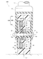
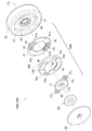
図11及び図12を参照する。図11及び図12には、実施例による手動カート10Bに用いられる発電機40B及び手動カート用信号発信装置50Bが示されている。図7及び図8に示された、発電機40A、手動カート用信号発信装置50に対して、永久磁石43が第1のプレート41にのみ固定される点において異なる。   Please refer to FIG. 11 and FIG. 11 and 12 show a generator 40B and a manual cart signal transmission device 50B used in the manual cart 10B according to the embodiment. 7 and 8 is different from the generator 40A and the manual cart signal transmission device 50 in that the permanent magnet 43 is fixed only to the first plate 41.

その他の基本的な構成については、参考例1による手動カート10及び/又は参考例2による手動カート10Aと共通する。参考例1及び/又は参考例2と共通する部分については、符号を流用すると共に、詳細な説明を省略する。   Other basic configurations are common to the manual cart 10 according to the reference example 1 and / or the manual cart 10A according to the reference example 2. About the part which is common in the reference example 1 and / or the reference example 2, while using a code | symbol, detailed description is abbreviate | omitted.

第2のプレート74Bのうち、永久磁石43に対向した部位には、磁性を有する金属によって構成された第2の金属板45(金属板45)が配置されている。各金属板は、軟鉄板で構成されている。   A second metal plate 45 (metal plate 45) made of a metal having magnetism is disposed in a portion of the second plate 74B facing the permanent magnet 43. Each metal plate is composed of a soft iron plate.

なお、鉛直方向に延びる車輪の中央線L1を基準として、第1のプレート41と第2のプレート74Bを逆に配置することもできる。即ち、外側(カバー部材35側)に第1のプレートを配置し、内側(ディスク部32側)に第2のプレートを配置することもできる。この場合には、欠肉部は、第1のプレートに形成されることとなる。   Note that the first plate 41 and the second plate 74B can be arranged in reverse, with the wheel center line L1 extending in the vertical direction as a reference. That is, the first plate can be arranged on the outer side (the cover member 35 side), and the second plate can be arranged on the inner side (the disk portion 32 side). In this case, the lacking portion is formed on the first plate.

このような構成の発電機40Bを採用した場合にも、本発明所定の効果を得ることができる。   Even when the generator 40B having such a configuration is adopted, the predetermined effect of the present invention can be obtained.

発電機40Bは、軸21が延びている方向に沿って永久磁石43、及び、金属板45が設けられ、これらの間にコイル48を配置した構成としている。本発明の構成では、コイル48を貫く磁束を変化させるための負荷が発生しない。このため、手動カート10Bの操作荷重の増加をほとんど感じない。即ち、発電機40Bを有しながらも操作性の高い手動カート10Bを提供できる。また、車輪30を組み立てる際に、車体11を必要としない。このため、車輪30のみを組み立てた上で、車体11に車輪30を取り付けることができる。このため、組立作業が簡便である。   The generator 40B has a configuration in which a permanent magnet 43 and a metal plate 45 are provided along the direction in which the shaft 21 extends, and a coil 48 is disposed therebetween. In the configuration of the present invention, a load for changing the magnetic flux passing through the coil 48 is not generated. For this reason, the increase in the operation load of the manual cart 10B is hardly felt. That is, it is possible to provide the manual cart 10B having high operability while having the generator 40B. Further, when assembling the wheels 30, the vehicle body 11 is not required. For this reason, the wheel 30 can be attached to the vehicle body 11 after assembling only the wheel 30. For this reason, the assembling work is simple.

さらに、永久磁石43は、第1のプレート41によってのみ保持している。発電機40Bを構成する部品点数を少なくすることができ、組み立てやすく、低コスト化できる。また、磁性を有する金属板45をカバー部材35側に配置した場合には、永久磁石43をより車輪30の内側(中央線L1側)に配置することができる。   Further, the permanent magnet 43 is held only by the first plate 41. The number of parts constituting the generator 40B can be reduced, and assembling is easy and the cost can be reduced. Further, when the metal plate 45 having magnetism is arranged on the cover member 35 side, the permanent magnet 43 can be arranged more inside the wheel 30 (center line L1 side).

さらに、金属板45は、第2のプレート74Bによって保持されている。第1のプレート41に第2のプレート74Bを取り付けることにより、容易に永久磁石43と金属板45とを対向させて配置することができる。さらに組立作業を簡便にすることができる。   Further, the metal plate 45 is held by the second plate 74B. By attaching the second plate 74B to the first plate 41, the permanent magnet 43 and the metal plate 45 can be easily arranged to face each other. Furthermore, assembly work can be simplified.

さらに、2つのプレート41,74Bのうちの一方のプレート41のみに永久磁石43が設けられている。即ち、2つのプレート41,74Bのうちの他方のプレート74Bには、永久磁石が用いられない。これにより、部品点数を削減することができる。   Further, the permanent magnet 43 is provided only on one of the two plates 41 and 74B. That is, a permanent magnet is not used for the other plate 74B of the two plates 41 and 74B. Thereby, the number of parts can be reduced.

さらに、永久磁石43は、第1のプレート41によって保持されている。第1のプレート41は、磁性を有する金属板45よりも内側に配置されている。これにより、永久磁石43をより車輪30の内側に配置することができる。これにより、カバー部材35より外側に磁束がほとんどもれなくなるため、地面に落下している鉄くず等のゴミが永久磁石43に付着することやカバー部材35に付着することを抑制できる。   Further, the permanent magnet 43 is held by the first plate 41. The first plate 41 is disposed inside the magnetic metal plate 45. Thereby, the permanent magnet 43 can be arrange | positioned inside the wheel 30 more. As a result, almost no magnetic flux leaks outside the cover member 35, so that it is possible to prevent dust such as iron scraps falling on the ground from adhering to the permanent magnet 43 and adhering to the cover member 35.

図13及び図14を参照する。図13及び図14には、変更例による手動カート10Cに用いられる発電機40C及び手動カート用信号発信装置50Cが示されている。図11及び図12に示された、発電機40Bに対して、金属板85は、第2のプレートを兼ねる点において異なる。   Please refer to FIG. 13 and FIG. 13 and 14 show a generator 40C and a manual cart signal transmission device 50C used in the manual cart 10C according to the modified example. The metal plate 85 differs from the generator 40B shown in FIGS. 11 and 12 in that it also serves as the second plate.

第1のプレート81は、ドーナツ板状のプレート本体81aと、このプレート本体81aの周縁から立ち上げられたプレート壁部81bと、プレート本体81aに空けられ車輪30と締結するための締結部材が通される締結部材挿通穴81cと、プレート壁部81bの端面から立ち上げられた位置決めピン81dと、を有している。   The first plate 81 has a donut plate-shaped plate body 81a, a plate wall portion 81b raised from the periphery of the plate body 81a, and a fastening member that is spaced from the plate body 81a and fastens to the wheel 30. The fastening member insertion hole 81c and the positioning pin 81d raised from the end surface of the plate wall portion 81b are provided.

金属板85は、第1のプレート81のプレート壁部81bに接着剤を介して固定されている。金属板85は、中央に円形の穴85aが開いたドーナツ形状の板材をベースとし、円形の穴85aから周方向外方に向かってさらに正方形状に切り欠いた欠肉部85b,85bが2カ所に設けられている。欠肉部85b,85bは、金属板85の中心を挟むように2カ所に形成されている。さらに、金属板85は、位置決めピン81dが通される位置決め穴85cが形成されている。   The metal plate 85 is fixed to the plate wall portion 81b of the first plate 81 with an adhesive. The metal plate 85 is based on a donut-shaped plate material having a circular hole 85a in the center, and has two undercut portions 85b and 85b that are further cut out in a square shape from the circular hole 85a outward in the circumferential direction. Is provided. The lacking portions 85b and 85b are formed at two locations so as to sandwich the center of the metal plate 85. Further, the metal plate 85 has a positioning hole 85c through which the positioning pin 81d is passed.

なお、金属板85は、第1のプレート81に保持されていればよく、第1のプレート81に対して必ずしも接着されている必要はない。   The metal plate 85 only needs to be held by the first plate 81, and is not necessarily bonded to the first plate 81.

位置決めピン81dの位置に位置決め穴85cの位置を合わせて、金属板85を第1のプレート81に載せることにより、簡便に第1のプレート81に対して金属板85を配置することができる。   By aligning the position of the positioning hole 85 c with the position of the positioning pin 81 d and placing the metal plate 85 on the first plate 81, the metal plate 85 can be easily placed on the first plate 81.

以上の構成により、本発明所定の効果を奏する。   With the above configuration, the present invention has a predetermined effect.

金属板85は、第1のプレート81に保持されている。金属板85を第1のプレート81に直接的に固定することにより、さらに部品点数を削減することができる。   The metal plate 85 is held by the first plate 81. By directly fixing the metal plate 85 to the first plate 81, the number of parts can be further reduced.

さらに、変更例は、参考例や実施例と比較して、永久磁石43と金属板45との間隔をより小さくできる。なぜならば、図7に示される参考例のような第2の永久磁石46が配置されておらず、また、図11に示される実施例のような第2のプレート74Bを不要としているためである。第2の永久磁石46や第2のプレート74Bの厚みの分、これらを不要とした変更例によれば、永久磁石43と金属板45との間隔をより小さくできる。これにより、コイル48を貫く磁束をより多くすることができる。その結果、より効率のいい発電機40Cとなる。同時に、構成部品を少なくすることができ、低コスト化も実現できる。   Furthermore, in the modified example, the distance between the permanent magnet 43 and the metal plate 45 can be made smaller than in the reference example and the example. This is because the second permanent magnet 46 as in the reference example shown in FIG. 7 is not disposed, and the second plate 74B as in the embodiment shown in FIG. 11 is unnecessary. . According to the modified example in which the second permanent magnet 46 and the second plate 74B are not necessary, the distance between the permanent magnet 43 and the metal plate 45 can be further reduced. Thereby, the magnetic flux which penetrates the coil 48 can be increased more. As a result, a more efficient generator 40C is obtained. At the same time, the number of components can be reduced and the cost can be reduced.

尚、本発明による手動カートは、ショッピングカートを例に説明したが、台車や乳母車等の手押し式の手動カートであっても適用可能である。さらに、スーツケースやゴルフカート等の手引き式のカートであっても適用可能である。即ち、操作者によって操作されるカートであればよく、これらの形式のものに限られるものではない。   The manual cart according to the present invention has been described by taking a shopping cart as an example, but it can also be applied to a hand-operated manual cart such as a cart or a baby carriage. Furthermore, the present invention can be applied to a hand-drawn cart such as a suitcase or a golf cart. That is, the cart may be operated by the operator, and is not limited to these types.

さらに、車輪は、適宜ブレーキや、ダンパーを付加することもできる。即ち、実施例に示された車輪に限らず、任意の車輪を採用することができる。   Furthermore, a brake and a damper can also be suitably added to a wheel. That is, not only the wheel shown in the Example but arbitrary wheels are employable.

実施例において、第1のプレートおよび第2のプレートを樹脂製で説明したが、樹脂に限定されず、非磁性物質が好適に利用できる。   In the embodiments, the first plate and the second plate have been described as being made of resin. However, the present invention is not limited to resin, and a nonmagnetic substance can be suitably used.

実施例において、永久磁石を軸21に対して対称となるように配置しているが、この配置に限定されるわけではない。隣接する永久磁石の極性が正、負のように異なっていればよく、軸21に対して対称的に配置しなくともよい。   In the embodiment, the permanent magnets are arranged so as to be symmetric with respect to the shaft 21, but the arrangement is not limited to this. Adjacent permanent magnets may be different in polarity, such as positive and negative, and may not be arranged symmetrically with respect to the axis 21.

各参考例、実施例や変更例は、適宜組み合わせることができる。例えば、実施例や変更例の手動カートに用いた発電機を参考例1の灯体が点灯される手動カートに用いることもできる。さらに、参考例2の信号送信機と、灯体の両方が搭載された手動カートとしてもよい。   Each reference example, example, and modification can be combined as appropriate. For example, the generator used in the manual cart of the embodiment or the modified example can be used for the manual cart in which the lamp body of the reference example 1 is turned on. Furthermore, it is good also as a manual cart carrying both the signal transmitter of the reference example 2, and a lamp.

本発明の作用及び効果を奏する限りにおいて、本発明は実施例に限られない。   As long as the effects and effects of the present invention are exhibited, the present invention is not limited to the examples.

本発明の手動カートは、ショッピングカートに好適である。   The manual cart of the present invention is suitable for a shopping cart.

10B,10C…手動カート
11…車体
21…ボルト(軸)
30…車輪
40B,40C…発電機
41,81…第1のプレート
43…第1の永久磁石(永久磁石)
45…第2の金属板(金属板)
48…コイル
74B…第2のプレート
74d,85b…欠肉部
77…コイルホルダ
77c…コイル保持部
85…金属板
10B, 10C ... Manual cart 11 ... Car body 21 ... Bolt (shaft)
30 ... Wheels 40B, 40C ... Generator 41, 81 ... First plate 43 ... First permanent magnet (permanent magnet)
45 ... Second metal plate (metal plate)
48 ... Coil 74B ... Second plate 74d, 85b ... Lack portion 77 ... Coil holder 77c ... Coil holding portion 85 ... Metal plate

Claims (4)

車体に設けられた軸と、この軸に回転可能に取り付けられた車輪と、この車輪に設けられ前記車輪が回転することにより発電する発電機と、を備えた手動カートにおいて、
前記発電機は、前記車輪の側面に沿って設けられ前記車輪と共に回転する第1のプレートと、この第1のプレートに保持された永久磁石と、この永久磁石に対向して設けられ前記第1のプレートと共に回転可能な金属板と、前記軸に設けられたコイルホルダと、このコイルホルダによって保持されたコイルと、を有し、
前記金属板は、磁性を有する金属によって構成され、
前記コイルは、前記永久磁石と前記金属板との間に位置していることを特徴とする手動カート。
In a manual cart comprising: a shaft provided on the vehicle body; a wheel rotatably attached to the shaft; and a generator provided on the wheel and generating electricity by rotating the wheel.
The generator is provided along a side surface of the wheel and rotates with the wheel, a permanent magnet held on the first plate, and the first magnet provided to face the permanent magnet. A metal plate that can be rotated together with the plate, a coil holder provided on the shaft, and a coil held by the coil holder,
The metal plate is made of magnetic metal,
The manual cart, wherein the coil is positioned between the permanent magnet and the metal plate.
前記金属板を保持すると共に前記第1のプレートに対向して設けられた第2のプレートをさらに有し、
前記金属板は、前記第2のプレートによって保持されていることを特徴とする請求項1記載の手動カート。
A second plate that holds the metal plate and is provided to face the first plate;
The manual cart according to claim 1, wherein the metal plate is held by the second plate.
前記金属板は、前記第1のプレートに保持されていることを特徴とする請求項1記載の手動カート。   The manual cart according to claim 1, wherein the metal plate is held by the first plate. 前記コイルホルダは、前記コイルを保持するコイル保持部を有し、
前記第1のプレート、又は、前記金属板のいずれかには、前記コイル保持部の形状に沿って欠肉状に形成された欠肉部を有していることを特徴とする請求項3に記載の手動カート。
The coil holder has a coil holding part for holding the coil,
Either the first plate or the metal plate has a thinned portion formed in a thin shape along the shape of the coil holding portion. Manual cart as described.
JP2016089905A 2016-04-27 2016-04-27 Hand operation cart Pending JP2017200331A (en)

Priority Applications (1)

Application Number Priority Date Filing Date Title
JP2016089905A JP2017200331A (en) 2016-04-27 2016-04-27 Hand operation cart

Applications Claiming Priority (1)

Application Number Priority Date Filing Date Title
JP2016089905A JP2017200331A (en) 2016-04-27 2016-04-27 Hand operation cart

Publications (1)

Publication Number Publication Date
JP2017200331A true JP2017200331A (en) 2017-11-02

Family

ID=60239667

Family Applications (1)

Application Number Title Priority Date Filing Date
JP2016089905A Pending JP2017200331A (en) 2016-04-27 2016-04-27 Hand operation cart

Country Status (1)

Country Link
JP (1) JP2017200331A (en)

Similar Documents

Publication Publication Date Title
US5920139A (en) Magnet motor stator
US8395291B2 (en) Transverse and/or commutated flux systems for electric bicycles
US8131413B2 (en) Electric motor and conversion system for manually powered vehicles
US20180111487A1 (en) Motor, motor system and charging and braking method
JP5397474B2 (en) Power generation device and braking device
JP2019099148A (en) Hub device and related system
US20120001521A1 (en) In-wheel motor and electrically driven vehicle
KR20110108493A (en) Electric bicycle using self-powered hub motor
US9595850B2 (en) Construction of motorized wheel for vehicle motorization
KR101543083B1 (en) Hybrid motor cycle with electric generating front wheel and driving rear wheel
JP3181650U (en) Non-contact torque sensor mechanism for electric vehicles
US20090195127A1 (en) Electric generator
JP5554427B2 (en) Electric tool with DC brushless motor
JP5335509B2 (en) Rotating electric machine
US7282831B2 (en) Generator in a wheel of a bicycle with collective multiple magnetic poles
JPH1042518A (en) Motor drive
JP3561527B2 (en) Dynamo for bicycle
JP7763657B2 (en) Components for human-powered vehicles
CN105228844A (en) For the drive wheel of vehicle
CN106218785B (en) Light-weight electric wheelbarrow
JP2017185859A (en) Signaling device for hand cart and hand cart
JP5547827B2 (en) Electric tool with DC brushless motor
JPH1052017A (en) Generator device for bicycle
US20080007145A1 (en) Bicycle with at least one generator
JPH10178761A (en) Motor