JP2017201121A - Road paver with support device - Google Patents
Road paver with support device Download PDFInfo
- Publication number
- JP2017201121A JP2017201121A JP2017075809A JP2017075809A JP2017201121A JP 2017201121 A JP2017201121 A JP 2017201121A JP 2017075809 A JP2017075809 A JP 2017075809A JP 2017075809 A JP2017075809 A JP 2017075809A JP 2017201121 A JP2017201121 A JP 2017201121A
- Authority
- JP
- Japan
- Prior art keywords
- bar
- paving machine
- road paving
- central bar
- extension bar
- Prior art date
- Legal status (The legal status is an assumption and is not a legal conclusion. Google has not performed a legal analysis and makes no representation as to the accuracy of the status listed.)
- Granted
Links
Images


Classifications
-
- E—FIXED CONSTRUCTIONS
- E01—CONSTRUCTION OF ROADS, RAILWAYS, OR BRIDGES
- E01C—CONSTRUCTION OF, OR SURFACES FOR, ROADS, SPORTS GROUNDS, OR THE LIKE; MACHINES OR AUXILIARY TOOLS FOR CONSTRUCTION OR REPAIR
- E01C19/00—Machines, tools or auxiliary devices for preparing or distributing paving materials, for working the placed materials, or for forming, consolidating, or finishing the paving
- E01C19/22—Machines, tools or auxiliary devices for preparing or distributing paving materials, for working the placed materials, or for forming, consolidating, or finishing the paving for consolidating or finishing laid-down unset materials
- E01C19/42—Machines for imparting a smooth finish to freshly-laid paving courses other than by rolling, tamping or vibrating
-
- E—FIXED CONSTRUCTIONS
- E01—CONSTRUCTION OF ROADS, RAILWAYS, OR BRIDGES
- E01C—CONSTRUCTION OF, OR SURFACES FOR, ROADS, SPORTS GROUNDS, OR THE LIKE; MACHINES OR AUXILIARY TOOLS FOR CONSTRUCTION OR REPAIR
- E01C19/00—Machines, tools or auxiliary devices for preparing or distributing paving materials, for working the placed materials, or for forming, consolidating, or finishing the paving
- E01C19/004—Devices for guiding or controlling the machines along a predetermined path
-
- E—FIXED CONSTRUCTIONS
- E01—CONSTRUCTION OF ROADS, RAILWAYS, OR BRIDGES
- E01C—CONSTRUCTION OF, OR SURFACES FOR, ROADS, SPORTS GROUNDS, OR THE LIKE; MACHINES OR AUXILIARY TOOLS FOR CONSTRUCTION OR REPAIR
- E01C19/00—Machines, tools or auxiliary devices for preparing or distributing paving materials, for working the placed materials, or for forming, consolidating, or finishing the paving
- E01C19/12—Machines, tools or auxiliary devices for preparing or distributing paving materials, for working the placed materials, or for forming, consolidating, or finishing the paving for distributing granular or liquid materials
-
- E—FIXED CONSTRUCTIONS
- E01—CONSTRUCTION OF ROADS, RAILWAYS, OR BRIDGES
- E01C—CONSTRUCTION OF, OR SURFACES FOR, ROADS, SPORTS GROUNDS, OR THE LIKE; MACHINES OR AUXILIARY TOOLS FOR CONSTRUCTION OR REPAIR
- E01C19/00—Machines, tools or auxiliary devices for preparing or distributing paving materials, for working the placed materials, or for forming, consolidating, or finishing the paving
- E01C19/48—Machines, tools or auxiliary devices for preparing or distributing paving materials, for working the placed materials, or for forming, consolidating, or finishing the paving for laying-down the materials and consolidating them, or finishing the surface, e.g. slip forms therefor, forming kerbs or gutters in a continuous operation in situ
-
- E—FIXED CONSTRUCTIONS
- E01—CONSTRUCTION OF ROADS, RAILWAYS, OR BRIDGES
- E01C—CONSTRUCTION OF, OR SURFACES FOR, ROADS, SPORTS GROUNDS, OR THE LIKE; MACHINES OR AUXILIARY TOOLS FOR CONSTRUCTION OR REPAIR
- E01C23/00—Auxiliary devices or arrangements for constructing, repairing, reconditioning, or taking-up road or like surfaces
- E01C23/01—Devices or auxiliary means for setting-out or checking the configuration of new surfacing, e.g. templates, screed or reference line supports; Applications of apparatus for measuring, indicating, or recording the surface configuration of existing surfacing, e.g. profilographs
-
- E—FIXED CONSTRUCTIONS
- E01—CONSTRUCTION OF ROADS, RAILWAYS, OR BRIDGES
- E01C—CONSTRUCTION OF, OR SURFACES FOR, ROADS, SPORTS GROUNDS, OR THE LIKE; MACHINES OR AUXILIARY TOOLS FOR CONSTRUCTION OR REPAIR
- E01C19/00—Machines, tools or auxiliary devices for preparing or distributing paving materials, for working the placed materials, or for forming, consolidating, or finishing the paving
- E01C19/48—Machines, tools or auxiliary devices for preparing or distributing paving materials, for working the placed materials, or for forming, consolidating, or finishing the paving for laying-down the materials and consolidating them, or finishing the surface, e.g. slip forms therefor, forming kerbs or gutters in a continuous operation in situ
- E01C19/4866—Machines, tools or auxiliary devices for preparing or distributing paving materials, for working the placed materials, or for forming, consolidating, or finishing the paving for laying-down the materials and consolidating them, or finishing the surface, e.g. slip forms therefor, forming kerbs or gutters in a continuous operation in situ with solely non-vibratory or non-percussive pressing or smoothing means for consolidating or finishing
- E01C19/4873—Apparatus designed for railless operation
-
- E—FIXED CONSTRUCTIONS
- E01—CONSTRUCTION OF ROADS, RAILWAYS, OR BRIDGES
- E01C—CONSTRUCTION OF, OR SURFACES FOR, ROADS, SPORTS GROUNDS, OR THE LIKE; MACHINES OR AUXILIARY TOOLS FOR CONSTRUCTION OR REPAIR
- E01C2301/00—Machine characteristics, parts or accessories not otherwise provided for
Landscapes
- Engineering & Computer Science (AREA)
- Architecture (AREA)
- Civil Engineering (AREA)
- Structural Engineering (AREA)
- Road Paving Machines (AREA)
Abstract
【課題】支持装置を有する道路舗装機械を提供する。【解決手段】本発明は、舗装層を敷設するための高さ調節可能なスクリード(2)、及び、少なくとも1つのセンサ部(7)を保持し位置決めするための少なくとも1つの支持装置(6)を有する道路舗装機械(1)に関する。支持装置(6)は、中央バー(11)と、中央バー(11)に対する少なくとも1つの延長バー(13)と、中央バー(11)の一端(12)に延長バー(13)を着脱可能に取り付ける少なくとも1つの取り付け部(18)とを含む。中央バー(11)と延長バー(13)とは、取り付け部(18)を介して、垂直投影面において、第1の取り付け角(α)にて互いに連結可能であり、中央バー(11)と延長バー(13)とは、取り付け部(18)を介して、垂直投影面において、少なくとも1つの更なる取り付け角(β)にて互いに連結可能である。【選択図】図1A road paving machine having a support device is provided. The invention relates to a height-adjustable screed (2) for laying a pavement layer and at least one support device (6) for holding and positioning at least one sensor part (7). The present invention relates to a road paving machine (1). The support device (6) is detachable from the central bar (11), at least one extension bar (13) with respect to the central bar (11), and one end (12) of the central bar (11). And at least one attachment portion (18) for attachment. The central bar (11) and the extension bar (13) can be connected to each other at the first mounting angle (α) on the vertical projection plane via the mounting portion (18). The extension bar (13) can be connected to each other at least one further attachment angle (β) in the vertical projection plane via the attachment (18). [Selection] Figure 1
Description
本発明は、請求項1のプリアンブルに係る、支持装置を有する道路舗装機械に関する。 The present invention relates to a road paving machine having a support device according to the preamble of claim 1.
道路舗装機械は、実際上、そこに配設されたスクリードを用いて新たな路面を敷設するために使用されている。これに関する舗装材料は道路舗装機械の材料ホッパから供給され、材料ホッパは、敷設方向において道路舗装機械の前方に設けられている。舗装材料は、材料搬送装置を介して材料ホッパから後方のスクリードに搬送され、拡散オーガによりスクリードの前方に拡散され、最終的に、加熱された締固め部を用いることによってスクリードの下方に敷設される。 Road paving machines are actually used for laying new road surfaces using screeds arranged there. The pavement material in this regard is supplied from the material hopper of the road paving machine, which is provided in front of the road paving machine in the laying direction. The pavement material is conveyed from the material hopper to the rear screed via the material conveying device, diffused in front of the screed by the diffusion auger, and finally laid under the screed by using a heated compaction. The
道路舗装機械が移動する路盤上に平坦な舗装を形成するために、スクリードは、高さ調節可能なスクリードビームを用いることによって道路舗装機械のシャーシに取り付けられている。スクリードの水平化は、道路舗装機械の制御装置によって制御される。スクリードは、路盤表面の状態又は形成される舗装の目標厚さに応じて水平に保たれる。 In order to form a flat pave on the roadbed on which the road paving machine moves, the screed is attached to the chassis of the road paving machine by using a height adjustable screed beam. The leveling of the screed is controlled by the control device of the road paving machine. The screed is kept horizontal depending on the condition of the roadbed surface or the target thickness of the pavement to be formed.
路盤の上方且つスクリードの後方に複数の高さ測定センサを支持するために、実際上、道路舗装機械のスクリードを水平に保つための測定バー装置を道路舗装機械に沿ってその側方で用いることが知られている。これにより、高さ測定センサの測定値に基づいてスクリードを水平に保つことができる。 In order to support multiple height measuring sensors above the roadbed and behind the screed, in practice a measuring bar device is used on the side along the road paving machine to keep the screed of the road paving machine horizontal. It has been known. Thereby, the screed can be kept horizontal based on the measured value of the height measuring sensor.
例えば、独国特許第60226237号(DE 60226237 T2)には、高さ測定のためのセンサを道路舗装機械側方において路盤の上方に配置するために、道路舗装機械に沿って伸縮自在なビームであって、互いに重なって配置されたビームを有する測定バー装置が記載されている。各伸縮性バーセグメントは、そこに設けられた固定具を用いて所望の箇所に取り付けることができる。さらに、各センサの高さ位置を調整することができる。上記装置においては、伸縮性測定バーはかなりの重量があり、特殊な型の道路舗装機械にしか適用できないという問題がある。また、測定バー装置の道路舗装機械への取り付け及び/又は取り外しには複数の人員が必要である。さらに、センサの設置高さについての選択肢に限りがある。 For example, German Patent No. 60226237 (DE 60226237 T2) describes a beam that can be stretched along a road paving machine in order to place a sensor for height measurement above the roadbed on the side of the road paving machine. A measuring bar device is described having beams arranged one above the other. Each stretchable bar segment can be attached to a desired location using a fixture provided there. Furthermore, the height position of each sensor can be adjusted. In the above apparatus, the elasticity measuring bar has a considerable weight, and there is a problem that it can be applied only to a special type of road paving machine. In addition, a plurality of personnel are required to attach and / or remove the measuring bar device to / from the road paving machine. In addition, there are limited options for the sensor installation height.
米国特許第5975473号(US5,975,473 A)には、道路舗装機械の側方に取り付けられた測定バー装置が開示されている。測定バー装置は、連節式旋回アームを介して、道路舗装機械のスクリードビームに取り付けられている。また、測定バー装置は、道路舗装機械に沿ってその側方に支持されると共に中央バー及びその端部に取り付けられた延長バーを有する測定バーを含む。中央バー及び延長バーのそれぞれには、高さ測定センサが取り付けられている。各延長バーは、水平面において、中央バーに対して内側に旋回可能であり、これにより、道路舗装機械の後部において後部延長バーに取り付けられたセンサを舗装スクリードの後方にて新たに敷設された舗装層の上方に配置することができる。この測定バー装置において、多関節手法で互いに接続された各連節セグメントは、ねじ継手を用いることによって連結されている。したがって、組み立ては非常に複雑な作業であり、多くの時間を要する。また、各ねじ継手には、最終的には、支持装置を調整するオペレータ次第で異なるクランプ力が加えられる。これにより、支持装置の取り付け及び調整はより複雑化し、その組み立てはすべての人が容易に行えるものではなくなる。また、このような複雑な測定バー装置において、個々の部品、特に、固定されていないスクリューレバーや、ねじや、クランプが作業現場で失われることも稀ではない。つまり、この測定バー装置では、各センサの高さ位置を調整する選択肢に限りがある。 US Pat. No. 5,975,473 (US 5,975,473 A) discloses a measuring bar device attached to the side of a road paving machine. The measuring bar device is attached to the screed beam of the road paving machine via an articulated swivel arm. The measurement bar device also includes a measurement bar supported laterally along the road paving machine and having a central bar and an extension bar attached to the end thereof. A height measuring sensor is attached to each of the center bar and the extension bar. Each extension bar is pivotable inward relative to the center bar in the horizontal plane, so that the sensor attached to the rear extension bar at the rear of the road paving machine is newly laid behind the pavement screed. It can be placed above the layer. In this measuring bar device, the articulated segments connected to each other by a multi-joint method are connected by using a threaded joint. Therefore, assembling is a very complicated operation and takes a lot of time. Each threaded joint is finally subjected to a different clamping force depending on the operator who adjusts the support device. This makes mounting and adjustment of the support device more complicated and its assembly is not easy for everyone. In such a complicated measuring bar device, it is not uncommon for individual parts, in particular, unfixed screw levers, screws and clamps to be lost at the work site. That is, in this measurement bar device, there are limited options for adjusting the height position of each sensor.
独国特許第69126017号(DE 69126017 T2)は、測定バーが取り付けられた道路舗装機械を開示している。この測定バーは、適用柔軟性に欠けており、道路舗装機械のスクリードビームの側方において路盤の上方に位置決めされている。これには、測定バーが、その適用柔軟性に欠けた構造のため、特に、限られた種類の道路舗装機械にしか適用できないという欠点がある。 German Patent No. 69126017 (DE 69126017 T2) discloses a road paving machine fitted with a measuring bar. This measuring bar lacks application flexibility and is positioned above the roadbed on the side of the screed beam of the road paving machine. This has the disadvantage that the measuring bar can be applied only to limited types of road paving machines, in particular because of its lack of flexibility in application.
従来技術における解決策を鑑みて、本発明は、様々な道路舗装機械においてとりわけ柔軟な適用性をもって使用するのに適し、道路舗装機械に対して簡単かつ迅速に取り付けることができるという特徴を有すると共に取り付けられるモジュール、特に、測定部を様々な形態で支持するように用いることのできる支持装置を有する道路舗装機械を提供することを目的とする。 In view of the solutions in the prior art, the present invention is suitable for use with a particularly flexible applicability in various road paving machines and has the feature that it can be easily and quickly attached to road paving machines. It is an object of the present invention to provide a road paving machine having a supporting device that can be used to support a module to be mounted, in particular, a measuring unit in various forms.
支持装置を有する道路舗装機械は、請求項1に開示されている。この発明の更なる発展事項は従属項の主題である。 A road paving machine having a support device is disclosed in claim 1. Further developments of the invention are subject matter of the dependent claims.
本発明に係る道路舗装機械は、高さ調節可能なスクリードであって、舗装層を敷設するためのスクリードと、少なくとも1つのセンサ部を保持し位置決めするための少なくとも1つの支持装置とを有する。支持装置は、中央バーと、中央バーに対する少なくとも1つの延長バーと、中央バーの一端に延長バーを着脱可能に取り付ける少なくとも1つの取り付け部とを含む。中央バーと延長バーとは、取り付け部を介して、鉛直投影面(vertical projection plane)において、第1の取り付け角にて互いに連結可能である。本発明に係る中央バーと延長バーとは、取り付け部を介して、鉛直投影面において、少なくとも1つの更なる取り付け角にて互いに連結可能である。 The road pavement machine according to the present invention is a screed whose height is adjustable, and includes a screed for laying a pavement layer and at least one support device for holding and positioning at least one sensor unit. The support device includes a central bar, at least one extension bar with respect to the central bar, and at least one attachment portion that detachably attaches the extension bar to one end of the central bar. The central bar and the extension bar can be connected to each other at a first mounting angle on the vertical projection plane via the mounting portion. The central bar and the extension bar according to the invention can be connected to each other at at least one further mounting angle in the vertical projection plane via the mounting portion.
このように、中央バーの端部に延長バーを取り付けるための少なくとも2つの取り付け方法があることで、用途に合わせて別々の支持装置を組み立てることができる。これにより、支持装置に保持されるセンサ部を、用途に合わせて、路盤又は新たに敷設された舗装層の上方において様々な高さで位置決めするために、支持装置を異なる種類の道路舗装機械に容易に適用することができる。 As described above, since there are at least two attachment methods for attaching the extension bar to the end portion of the central bar, separate support devices can be assembled according to the application. This allows the support device to be placed on different types of road paving machines in order to position the sensor unit held by the support device at various heights above the roadbed or newly laid paving layer, depending on the application. Can be easily applied.
本発明においては、支持装置上で用いられる各センサ部のそれぞれを、用途に応じて、異なる測定基準又は測定位置に自由に配置することができる。その結果、支持装置を、利用者の要求に応じた様々な用途で使用することができる。特に、本発明では、各センサをとりわけ多様な方法で位置決めすることができる。本発明においては、取り付け部は、中央バー及び延長バーを様々な形態で組み立てられるように構成されている。その結果、支持装置の適用範囲は広がり、特に、様々な種類の道路舗装機械において、標準モジュールとして用いることができる。鉛直面(vertical plane)における調節が可能であるために、支持装置は大型、小型両方の道路舗装機械に好適である。これにより、様々な種類のセンサの利用が促進される。 In the present invention, each of the sensor units used on the support device can be freely arranged at different measurement standards or measurement positions depending on the application. As a result, the support device can be used for various purposes according to the user's request. In particular, in the present invention, each sensor can be positioned in various ways. In the present invention, the attachment portion is configured so that the central bar and the extension bar can be assembled in various forms. As a result, the application range of the support device is widened, and can be used as a standard module in various types of road paving machines. Due to the possibility of adjustment in the vertical plane, the support device is suitable for both large and small road paving machines. This facilitates the use of various types of sensors.
支持装置は、好ましくは、鉛直面において、第1の取り付け角及び更なる取り付け角を成す、肢部(limbs)及び頂点(apex points)を含む。 The support device preferably includes limbs and apex points that form a first attachment angle and a further attachment angle in a vertical plane.
支持装置は、好ましくは、少なくとも1つの追加の延長バーと、もう1つの更なる取り付け部とを含む。追加の延長バーは、更なる取り付け部を介して、中央バーの他端又は既に存在する延長バーに着脱可能に取り付けられる。追加の延長バーにより、支持装置を十分な長さに延長することができるので、支持装置を用いることによって、路盤上の長い距離に亘る測定が可能となる。 The support device preferably includes at least one additional extension bar and another further attachment. The additional extension bar is detachably attached to the other end of the central bar or an already existing extension bar via a further attachment. Since the support device can be extended to a sufficient length by the additional extension bar, the measurement over a long distance on the roadbed is possible by using the support device.
本発明では、異なる保持アームを、水平方向及び鉛直投影面において、所望のモジュールとして組み立て、拡張することができる。特に、中央バーからそこに連結された延長バーの自由端のそれぞれまで直線状に延びる保持バー、及び、鉛直面において互いにオフセットさせて配置された延長バーを含む階段状の保持バーモジュールを組み立てることができる。また、先頭及び最後尾の延長バーを路盤近くで保持するために、中央バーの前後に延びる2つの階段状の延長バーを有するアッセンブリが考えられ得る。このような変形例においては、中央バーを、鉛直面において、上方、特に、水平方向に変位させて、道路舗装機械に取り付けることができる。 In the present invention, different holding arms can be assembled and expanded as desired modules in the horizontal and vertical projection planes. In particular, assembling a stepped holding bar module comprising a holding bar extending linearly from the central bar to each of the free ends of the extension bar connected thereto, and extension bars arranged offset from each other in the vertical plane Can do. Also, an assembly having two stepped extension bars extending back and forth of the central bar can be considered to hold the leading and trailing extension bars near the roadbed. In such a variant, the central bar can be displaced upwards, particularly in the horizontal direction, on the vertical plane and attached to the road paving machine.
別の態様によれば、2つの延長バーは、所定の距離をあけて互いに平行に延びるように中央バーの両端に取り付け可能である。その結果、2つの延長バーは中央バーと共に階段状に形成され、延長バーは互いに所定の距離を保って延びている。センサ部のセンサのそれぞれは、このバーアッセンブリを介して、とりわけ多様な手法で、路盤又は敷設された舗装面に対して様々な高さにて位置決めされ得る。特に、センサを、スクリードの後方において、高温の舗装面の上方に予め定められた最低限の高さを保って容易に位置決めすることができる。その結果、スクリードの後方において、立ち昇る蒸気と熱からセンサを保護することができる。 According to another aspect, the two extension bars can be attached to both ends of the central bar to extend parallel to each other at a predetermined distance. As a result, the two extension bars are formed stepwise together with the center bar, and the extension bars extend at a predetermined distance from each other. Each of the sensors of the sensor part can be positioned at various heights with respect to the roadbed or the laid pavement surface, in particular in various ways, via this bar assembly. In particular, the sensor can be easily positioned behind the screed while maintaining a predetermined minimum height above the hot pavement surface. As a result, the sensor can be protected from rising steam and heat behind the screed.
階段状に形成されることによって、さらに、道路舗装機械が移動する路盤の上方において、センサ部を、新たに敷設された舗装層の上方で他のセンサ部が保持されている高さと同じ高さに位置決めすることができる。 By forming in a staircase shape, the sensor unit is located above the roadbed on which the road paving machine moves, and the same height as the other sensor units held above the newly laid pavement layer. Can be positioned.
一方、階段状の構造は、特に大規模な舗装工事を行う場合に、支持装置が道路舗装機械のその他のコンポーネント、例えば、スクリード延長部材、チャネルプレート、及び/又は、これらの支持部材に衝突することがないという実質的な利点がある。舗装幅が大きい場合、スクリードの延長部材、及び/又は、進行方向で視て延長部材の前方に配置されたチャネルプレートは、鉛直方向及び水平方向において外方に突出した支持ロッドを用いることによって固定されてもよい。支持装置の階段状の構造により、このような支持ロッドの使用が可能となるが、支持装置自体の機能が支持ロッドにより損なわれることはない。本発明のさらなる変形例によれば、中央バーは、スクリードアーム又はスクリードの側板、特に、スクリードを拡張するスクリード延長部材の側板に取り付けられている。側板に取り付けられることにより、支持装置に対してスクリードビームの動きが少なくとも直接伝わることはない。支持装置を側板に取り付けることで更に、階段状の配置であるか又は直線状の配置であるかに関係なく、支持装置と上記支持ロッドとの干渉が回避されるという利点がある。 On the other hand, the stepped structure causes the support device to collide with other components of the road paving machine, such as screed extension members, channel plates, and / or these support members, especially when performing large paving work. There is a substantial advantage that there is nothing. If the pavement width is large, the screed extension member and / or the channel plate placed in front of the extension member when viewed in the direction of travel is fixed by using support rods that protrude outward in the vertical and horizontal directions. May be. Such a support rod can be used because of the stepped structure of the support device, but the function of the support device itself is not impaired by the support rod. According to a further variant of the invention, the central bar is attached to the side plate of the screed arm or screed, in particular the side plate of the screed extension member that expands the screed. By being attached to the side plates, the movement of the screed beam is not transmitted at least directly to the support device. By attaching the support device to the side plate, there is an advantage that interference between the support device and the support rod is avoided regardless of the stepped arrangement or the linear arrangement.
スクリードビームに取り付けられることで、道路舗装機械の近くで高さ測定を実行することができる。各取り付け部は、好ましくは、フックジョー(hook-in jaw)と固定板とを含む。固定板は、取り付け部のフックジョーに対して、簡単且つ迅速に引っ掛けて固定することができ、そこに位置決めされる。さらに、互いに連結されるフックジョーと固定板のいずれにも、緩く固定された部材はないので、建設現場の使用に適している。 By being attached to the screed beam, height measurements can be performed near the road paving machine. Each attachment preferably includes a hook-in jaw and a securing plate. The fixing plate can be easily and quickly hooked and fixed to the hook jaw of the mounting portion, and is positioned there. Further, since neither the hook jaws or the fixing plates connected to each other have any loosely fixed members, they are suitable for use at the construction site.
複数のフックが固定板に形成され、フックを引っ掛けるための複数のボルトがフックジョーに形成されている場合、固定板及びフックジョーを、とりわけ迅速に且つ安定して所望の組み立て位置に位置合わせすることができる。よって、誤って組み立てられる可能性は低い。さらに、組み立ては治具を用いることなく行うことができる。 When a plurality of hooks are formed on the fixing plate and a plurality of bolts for hooking the hook are formed on the hook jaw, the fixing plate and the hook jaw are particularly quickly and stably aligned to the desired assembly position. be able to. Therefore, it is unlikely to be assembled by mistake. Furthermore, the assembly can be performed without using a jig.
延長バーを中央バーに対して安定して位置合わせするために、又は2つの延長バー同士を安定して位置合わせするために、各取り付け部のフックジョーは、第1及び第2側壁を有し、これら2つの側壁間にボルトが延びている。2つの側壁は、固定板のための疑似的な(quasi)ガイドを形成し、これにより固定板とフックジョーとを適切に連結することができる。2つの側壁により、水平面(horizontal plane)において、中央バー及びこれに取り付けられた延長バー同士の動き、又は、互いに隣接して連結された2つの延長バー同士の動きを妨げることができる。その結果、支持装置を、水平投影面で視て、舗装方向において道路舗装機械の側方にて堅固に保持することができる。 In order to stably align the extension bar with respect to the central bar, or to stably align the two extension bars, the hook jaw of each attachment portion has first and second side walls. A bolt extends between the two side walls. The two side walls form a quasi guide for the fixing plate, which can properly connect the fixing plate and the hook jaw. The two side walls can prevent the movement of the central bar and the extension bars attached thereto or the movement of two extension bars connected adjacent to each other in the horizontal plane. As a result, the support device can be firmly held on the side of the road paving machine in the pavement direction when viewed in the horizontal projection plane.
フックジョーが第1及び第2群のボルトを含む場合、中央バーの一端における延長バーの組み立て、及び/又は、第1の取り付け角若しくは更なる取り付け角にて取り付けられた2つの延長バーの組み立てをとりわけ容易に行うことが可能である。この場合において、中央バーと延長バーとを、固定板のフックを第1群のボルトに連結することによって互いに第1の取り付け角をもって連結することができる。また、中央バーと延長バーとを、固定板のフックを第2群のボルトに連結することによって、更なる取り付け角をもって互いに連結することができる。これと同様に、延長バー同士も連結することができる。アッセンブリによっては、ボルト群及びそこに引っ掛けたフックにより、操作者は他人のさらなる助けを必要とすることなく、支持装置の道路舗装機械への適切な取り付けを容易に行うことができる。 When the hook jaw includes first and second groups of bolts, the assembly of the extension bar at one end of the central bar and / or the assembly of two extension bars attached at the first or further mounting angle Can be carried out particularly easily. In this case, the central bar and the extension bar can be connected to each other with a first mounting angle by connecting the hook of the fixing plate to the first group of bolts. Further, the central bar and the extension bar can be connected to each other with a further mounting angle by connecting the hook of the fixing plate to the second group of bolts. Similarly, the extension bars can be connected to each other. In some assemblies, the group of bolts and hooks hooked thereon allow the operator to easily make the proper attachment of the support device to the road paving machine without the need for further help from others.
更なる変形例によれば、中央バーは、両端に、フックジョーを含み、延長バーは、一端に、中央バーのフックジョーの一方に連結するための固定板を含む。支持装置の組み立て中、中央バーが既に道路舗装機械に取り付けられている場合、延長バーを中央バーの端部に対して、簡単に取り付けて、位置合わせして固定することができる。 According to a further variation, the central bar includes hook jaws at both ends and the extension bar includes a securing plate at one end for connection to one of the hook jaws of the central bar. During assembly of the support device, if the central bar is already attached to the road paving machine, the extension bar can be easily attached, aligned and secured to the end of the central bar.
特に、2つのフックジョーが中央バーの両端部において互いにミラー反転(mirror-inverted)するように構成されていることにより、中央バーを多様な形態に拡張することができる。2つのフックジョーは、基本的には、中央バーの両端部において映進対称(glide reflection)に設けられている。ボルトの群のそれぞれは、中央バーの両端部のそれぞれにおいて、互いにオフセットして配置されており、これにより、延長バーを中央バーの両端に、第1の取り付け角及び更なる取り付け角をもって取り付けることができる。これにより、支持装置は、それぞれのバーとの連結形態を直線状と階段状とに迅速に変更することができる。 In particular, since the two hook jaws are configured to be mirror-inverted with each other at both ends of the central bar, the central bar can be expanded into various forms. The two hook jaws are basically provided in a glide reflection at both ends of the central bar. Each of the groups of bolts are arranged offset from each other at each end of the central bar, thereby attaching the extension bar to both ends of the central bar with a first mounting angle and a further mounting angle. Can do. Thereby, the support apparatus can change rapidly the connection form with each bar | burr to linear form and step shape.
延長バーは、好ましくは、中央バーとは反対側の端部に、フックジョー又は更なる固定板を含む。先の態様で述べたように、更なる延長バーの固定板は簡単に引っ掛けて位置合わせされ得る。これは、一人のオペレータによって簡単に行われる。 The extension bar preferably includes a hook jaw or a further fixing plate at the end opposite the central bar. As mentioned in the previous embodiment, the securing plate of the further extension bar can be easily hooked and aligned. This is easily done by a single operator.
好ましくは、第1の取り付け角は、鈍角であり、更なる取り付け角は、180°である。その結果、保持バーモジュールは、特に、直線状及び階段状に組み立て可能である。これらの連結形態は、様々な種類のスクリード、特に、このために設計されたスクリードビームを取り付けるのにとりわけ好適である。 Preferably, the first mounting angle is an obtuse angle and the further mounting angle is 180 °. As a result, the holding bar module can be assembled in particular in a straight line and a staircase. These connection forms are particularly suitable for mounting various types of screed, in particular screed beams designed for this purpose.
延長バーを中央バーに固定する取り付け部は、好ましくは、固定位置(locking position)と解除位置(release position)との間で移動可能な固定ボルトを含む。固定位置において、固定ボルトを、好ましくは、フックジョーのボルトに対して位置決めすることができ、これにより、ボルトに引っ掛けられたフックが固定される。固定ボルトの解除及び固定は、治具を用いることなく、片手で迅速且つ簡単に行うことができる。これにより、支持装置全体の使い心地が向上する。 The attachment that secures the extension bar to the central bar preferably includes a fastening bolt that is movable between a locking position and a release position. In the fixed position, the fixing bolt can preferably be positioned with respect to the bolt of the hook jaw so that the hook hooked on the bolt is fixed. Release and fixing of the fixing bolt can be performed quickly and easily with one hand without using a jig. Thereby, the usability of the whole support device is improved.
固定ボルトは、好ましくは、解除位置で固定可能である。例えば、解除位置(release position)において、固定ボルトは、リリースシート(release seat)まで回転し、これにより固定ボルト自身が固定位置に戻ってしまうことを防止することができる。 The fixing bolt is preferably fixable in the release position. For example, in the release position, the fixing bolt can be rotated to the release seat, thereby preventing the fixing bolt itself from returning to the fixing position.
固定位置においてバネがプリロード(preloaded)されている場合、固定ボルトを解除位置及び固定位置において特に堅固に保持することができる。固定ボルトに作用するバネ力により、固定ボルトは、固定位置において堅固に保持され、また、解除位置にある場合も、固定ボルトは、リリースシートに固定される。 If the spring is preloaded in the fixed position, the fixing bolt can be held particularly firmly in the release position and in the fixed position. Due to the spring force acting on the fixing bolt, the fixing bolt is firmly held in the fixing position, and the fixing bolt is also fixed to the release seat even in the release position.
センサ部は、好ましくは、複数のセンサを有し、各センサは、道路舗装機械が移動する路盤までの距離を測定し、及び/又は、スクリードの後方に新たに敷設された舗装面までの距離を測定する。このために、各センサは、好ましくは、レーザー及び/又は超音波センサである。スクリードの自動水平化は、新たな舗装を路盤上に形成するために、道路舗装機械に設けられた制御装置を用いることによって、それぞれの高さ測定値に基づいて実行される。センサは支持装置に沿って様々な箇所に位置決めされ得る。特に、鉛直投影面で視た場合、上流に位置する支持装置の調節性能によって、各センサの高さ調節性能が向上する。 The sensor section preferably has a plurality of sensors, each sensor measuring the distance to the roadbed on which the road paving machine moves and / or the distance to the newly paved surface behind the screed. Measure. For this purpose, each sensor is preferably a laser and / or an ultrasonic sensor. The automatic leveling of the screed is carried out on the basis of the respective height measurements by using a control device provided on the road paving machine in order to form a new pavement on the roadbed. The sensor can be positioned at various locations along the support device. In particular, when viewed on a vertical projection plane, the height adjustment performance of each sensor is improved by the adjustment performance of the support device located upstream.
中央バー及び/又は延長バーは、好ましくは、アルミプロファイル、特に、アルミフォームプロファイルで形成されている。これにより、支持装置の重量を抑えることができる。さらに、更なるモジュールを支持装置にとりわけ好適に取り付けることができる。中央バー及び/又は延長バーについては、上記以外の材料を用いることも考えられ得る。 The central bar and / or extension bar is preferably formed of an aluminum profile, in particular an aluminum foam profile. Thereby, the weight of a support apparatus can be restrained. Furthermore, a further module can be particularly suitably attached to the support device. It is also conceivable to use materials other than those described above for the central bar and / or extension bar.
好ましくは、支持装置は、平面視で道路舗装機械の進行方向に沿って直線状に形成される。その一方、平面視で、水平投影面において階段状に形成することも可能であり、これにより、水平投影面で視て、2つの延長バーは、互いに平行に中央バーに対して固定される。その結果、延長バーに取り付けられたセンサは、様々な距離をもって道路舗装機械の側方に位置決めされ得る。 Preferably, the support device is formed linearly along the traveling direction of the road paving machine in plan view. On the other hand, it is also possible to form a stepped shape on the horizontal projection plane in a plan view, whereby the two extension bars are fixed to the central bar in parallel with each other as viewed in the horizontal projection plane. As a result, the sensors attached to the extension bar can be positioned to the side of the road paving machine at various distances.
以下の添付図面を参照して本発明の実施形態について説明する。図中、同じ部品には同じ参照符号を付している。 Embodiments of the present invention will be described with reference to the accompanying drawings. In the figure, the same parts are denoted by the same reference numerals.
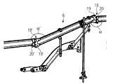
図1は、スクリード2を牽引する道路舗装機械1を示す。スクリード2は、路盤8上に新たに舗装層3を敷設するように構成されている。道路舗装機械1はさらに、材料ホッパ4を含み、舗装層3を敷設するために、舗装材料は、道路舗装機械1内で駆動する搬送コンベア(図示省略)を用いることによって、材料ホッパ4から後方のスクリード2に搬送される。
FIG. 1 shows a road paving machine 1 that pulls a
スクリード2のスクリードビーム5には、支持装置6が取り付けられている。支持装置6は、少なくとも1つのセンサ部7を保持し位置決めするものである。センサ部7は、特に、道路舗装機械1が移動する路盤8までの距離を検出するように構成されている。図1において、支持装置6には、合計3つのセンサ部7が配設されており、そのうち2つのセンサ部7は移動方向Fで視て前部に設けられると共に路盤8までの距離を測定し、センサ部7’は支持装置の後端に設けられると共に新たに敷設された舗装層3までの距離を測定する。道路舗装機械1は、路盤8及び/又は新しい舗装層3までの高さ測定値に基づいて、制御装置33を用いてスクリード2の自動水平化を実行することができる。
A
支持装置6は、第1及び第2旋回アーム9、9’を含み、これらを介して、支持装置が道路舗装機械1のスクリードビーム5に取り付けられている。スクリードビーム5外方に横方向にずらして設けられた各旋回アーム9、9’の両端のそれぞれには、クランプ装置10、10’が取り付けられている。クランプ装置は簡易着脱式の固定装置であり、支持装置6の中央バー11を保持するものである。中央バー11は、道路舗装機械1の移動方向Fにおいて、水平方向に対して前方に傾斜した状態で位置合わせされている。
The
移動方向Fにおいて後部に位置する、中央バー11の端部12には、中央バー11に対する延長バー13が取り付けられている。中央バー11と延長バー13とは、鉛直投影面で視て第1の取り付け角αにて互いに連結されている。さらに後方において、中央バー11の反対側に位置する延長バー13の端部14には、新たに敷設された舗装層3の上方でセンサ部7’を保持するための更なる延長バー13’が取り付けられている。2つの延長バー13、13’は路盤8又はその上に形成された舗装層3に対して水平に位置合わせされている。
An
移動方向Fにおいて前部に位置する、中央バー11の端部15には、追加の前部延長バー16が取り付けられている。追加の前部延長バー16は、その長さ方向において、センサ部7を路盤8の上方で保持する更なる前部延長バー16’によって延長されている。中央バー11と追加の前部延長バー16とは、取り付け角α’にて互いに連結されており、ここで取り付け角α’及び第1取り付け角αは錯角(alternate angles)であり、その結果、図1では、延長バー13及び追加の前部延長バー16は、支持装置6におけるバーセグメントとして互いに平行に配置されている。
An additional
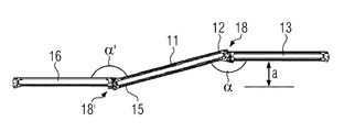
図2は、図1の支持装置6の一部を示している。図2に示すように、中央バー11は、両端部12、15に、それぞれ取り付け部18、18’を含む。取り付け部18、18’は、延長バー13及び追加の前部延長バー16を中央バー11の端部12、15に連結するものである。図2において、2つの延長バー13、16は、中央バー11を介して、階段状に配置されると共にそれぞれ錯角又はZ角α、α’をもって互いに連結されている。
FIG. 2 shows a part of the
図3は、その各端部12、15に延長バー13、16が取り付けられた中央バー11の階段状のアッセンブリのみを示している。2つの延長バー13、16は、中央バー11を介して互いに平行に延びているため、取り付け角α、α’は、錯角、すなわち、Z角となる。
FIG. 3 shows only the step-like assembly of the
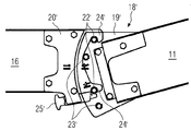
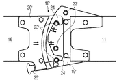
図4の拡大図に示すように、取り付け部18は、延長バー13を中央バー11の後端12に取り付けるものである。取り付け部18は、中央バー11に形成されたフックジョー(hook-in jaw)19と、延長バー13に形成された固定板20とを含む。延長バー13の固定板20は、鉛直投影面で視て中央バー11と延長バー13とが第1の取り付け角αにて互いに連結されるように、中央バー11のフックジョー19に取り付けられている。
As shown in the enlarged view of FIG. 4, the
図4にさらに示すように、フックジョー19は、第1群22と第2群23とに分類される複数のボルト21を含む。固定板20は、第1群22のボルト21に取り付けられる2つのフック24を有する。各取り付け部18、18’において、フック24、24’を第1群22、22’のボルト21、21’に固定することにより、中央バーとこれに取り付けられた複数の延長バーとの間で階段状の構造が形成される(図4及び図5参照)。一方、フック24を第2群23、23’のボルト21、21’に引っ掛けることにより、直線状のビームアッセンブリが形成される(図7及び図8参照)。
As further shown in FIG. 4, the
図4に示すように、固定板20の底部に形成されたフック24は、固定ボルト25を用いることによって第1群22のボルト21のうち下側のボルト21に固定されている。
As shown in FIG. 4, the
図5は、中央バー11の前端15に形成された更なる取り付け部18’を示している。取り付け部18’は、中央バー11の前端15に、フックジョー19’であって、そこに固定板20’が引っ掛けられるフックジョー19’を含む。固定板20’は、延長バー16に形成されると共にそこに取り付けられた固定ボルト25’を介して、フックジョー19’に固定されている。図5において、フックジョー19’は、鉛直面で視て、図4に示すフックジョー19のミラー反転するように構成されている。これにより、階段状及び直線状となるように、中央バー11を各延長バー13、16に連結することができる。図4と類似した図5に示す固定板20’は、2つのフック24’を含み、これらフックは、フックジョー19’の第1群22’のボルト21’に取り付けられている。
FIG. 5 shows a
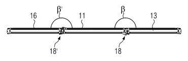
図6は、延長バー13、16を有する中央バー11のアッセンブリが直線状となった実施形態を示す。中央バー11及び延長バー13、16は、更なる取り付け角β、β’をもって互いに連結されている。図6では、更なる取り付け角β、β’は180°であり、これにより、直線状のバーアッセンブリが形成される。
FIG. 6 shows an embodiment in which the assembly of the
図7及び図8は図6に示す各取り付け部18、18’の固定位置を示している。
7 and 8 show the fixing positions of the mounting
図7において、フック24が設けられた固定板20は、中央バー11のフックジョー19において、第2群23のボルト21に取り付けられている。このように取り付けることによって、図4と対照的に、延長バー13を有する中央バー11の更なる取り付け角βによる直線状のアッセンブリが形成される。
In FIG. 7, the fixing
図8は、中央バー11の前端15に形成された取り付け部18’を示しており、ここで、フック24’もまた第2群23’のボルト21’に取り付けられている。これにより、直線状となるように、中央バー11の前端を追加の延長バー16に連結することもできる。
FIG. 8 shows an attachment 18 'formed at the
図9は、図8に示す取り付け部18’であって、固定位置における取り付け部18’の拡大図である。固定位置において、下側のボルト21’の上方から引っ掛けたフック24’をフックジョー19’に固定するために、その前端26’が第2群23’のボルト21’のうち下側のボルト21’の下方に配置された固定ボルト25’が存在している。固定位置において固定ボルト25’がボルト21’に当接して歪むことがないように、固定ボルト25’の前端26’は、好ましくは、円錐状、特に、ボルト21’の真下の部分がテーパ状となるように形成されている。
FIG. 9 is an enlarged view of the
図9に更に示すように、固定ボルト25’は、バネ27’によって固定位置に押し付けられている(pressed into)。 As further shown in FIG. 9, the fixing bolt 25 'is pressed into a fixed position by a spring 27'.
図10は、図9に示す固定ボルト25’であって、解除位置における固定ボルト25’を示す図である。解除位置では、固定ボルト25’の前端26’がボルト21’の下方において横方向にボルト21’から遠ざかることにより、フック24’のボルト21’に対する固定が解除される。解除位置では、延長バー16を中央バー11から取り外すことができる。図10に更に示すように、解除位置にある固定ボルト25’は、リリースシート(release seat)28’内に後退する。このために、固定ボルト25’が取り付け軸(mounting axis)周りに回転することによってリリースシート28’に向かって移動することができ、これにより、バネ27’のバネ力で固定ボルト25’が保持された状態となる。
FIG. 10 is a view showing the fixing
図11は、図10に示す固定ボルト25’の固定位置を示す断面図である。図11において、固定ボルト25’は、その頭部29’及びその前端26’であってガイド30’に保持された前端26’を有する。バネ27’により、固定ボルト25’のテーパ状に形成された前端26’がボルト21’に押し付けられている。図11に更に示すように、フックジョー19’の固定ボルト21’は第1側壁31’と第2側壁32’の間に延びている。第1及び第2側壁31’、32’は共に、固定板20’の安定したシート及びガイドを構成し、これにより、固定板20’は水平面において、揺動することがない。これにより、中央バー11に固定された延長バー16は、水平面で視て、移動方向Fにおいて道路舗装機械の側方に安定して位置決めされた状態となっている。
FIG. 11 is a sectional view showing a fixing position of the fixing
図12は、図11に示す固定ボルト25’であって、解除位置にある固定ボルト25’を示す図である。この位置では、固定ボルト25’の頭部29’は、固定位置と比較して取り付け軸周りに90°回転しており、ガイド30’のリリースシート28’上に着座している。
FIG. 12 is a view showing the fixing
上記説明では、道路舗装機械に限って支持装置の説明を行ったが、その他の車両、例えば、道路舗装機械の補給車に搭載することもできる。
In the above description, the support device has been described only for the road paving machine, but it can also be mounted on other vehicles, for example, a replenishment vehicle for the road paving machine.
Claims (16)
少なくとも1つのセンサ部(7)を保持し位置決めするための少なくとも1つの支持装置(6)であって、中央バー(11)、前記中央バー(11)に対する少なくとも1つの延長バー(13)、及び、前記中央バー(11)の一端(12)に前記延長バー(13)を着脱可能に取り付ける少なくとも1つの取り付け部(18)を含む前記少なくとも1つの支持装置(6)と、
を有する道路舗装機械(1)であって、
前記中央バー(11)と前記延長バー(13)とは、前記取り付け部(18)を介して、鉛直投影面で視て、第1の取り付け角(α)にて互いに連結可能であり、
前記中央バー(11)と前記延長バー(13)とは、前記取り付け部(18)を介して、鉛直投影面で視て、少なくとも1つの更なる取り付け角(β)にて互いに連結可能であることを特徴とする道路舗装機械。 A height adjustable screed (2), said screed (2) for laying a pavement layer;
At least one support device (6) for holding and positioning at least one sensor part (7), comprising a central bar (11), at least one extension bar (13) relative to said central bar (11), and The at least one support device (6) including at least one attachment portion (18) for removably attaching the extension bar (13) to one end (12) of the central bar (11);
Road paving machine (1) having
The central bar (11) and the extension bar (13) can be connected to each other at a first mounting angle (α) when viewed in a vertical projection plane through the mounting portion (18).
The central bar (11) and the extension bar (13) can be connected to each other at at least one further mounting angle (β) as viewed in the vertical projection plane via the mounting portion (18). Road paving machine characterized by that.
前記追加の延長バー(16)は、前記更なる取り付け部(18’)を介して、前記中央バー(11)の他端(15)に着脱可能に取り付けられていることを特徴とする請求項1に記載の道路舗装機械。 Said support device (6) comprises at least one additional extension bar (16) and another further attachment (18 ');
The additional extension bar (16) is detachably attached to the other end (15) of the central bar (11) via the further attachment (18 '). The road paving machine according to 1.
前記中央バー(11)と前記延長バー(13)とは、前記固定板(20)の前記フック(24)を前記第1の群(22)のボルト(21)に連結することにより互いに第1の取り付け角(α)にて取り付けられ、
前記中央バー(11)と前記延長バー(13)とは、前記固定板(20)の前記フック(24)を前記第2群(23)のボルト(21)に連結することにより互いに前記更なる取り付け角(β)にて取り付けられることを特徴とする請求項6又は請求項7に記載の道路舗装機械。 The hook jaw (19) includes bolts (21) of first and second groups (22, 23);
The central bar (11) and the extension bar (13) are connected to each other by connecting the hook (24) of the fixing plate (20) to the bolt (21) of the first group (22). It is attached at the mounting angle (α)
The central bar (11) and the extension bar (13) are connected to each other by connecting the hook (24) of the fixing plate (20) to the bolt (21) of the second group (23). The road paving machine according to claim 6 or 7, wherein the road paving machine is attached at an attachment angle (β).
前記延長バー(13、13’)は、その一端に、前記中央バー(11)の前記フックジョー(19、19’)の一方に連結するための前記固定板(20、20’)を含むことを特徴とする請求項5〜請求項8のいずれか1つに記載の道路舗装機械。 The central bar (11) includes the hook jaws (19, 19 ′) at both ends (12, 15);
The extension bar (13, 13 ′) includes, at one end thereof, the fixing plate (20, 20 ′) for connecting to one of the hook jaws (19, 19 ′) of the central bar (11). The road pavement machine according to any one of claims 5 to 8, wherein
The road paving machine according to any one of claims 1 to 15, wherein the support device (6) can be assembled without using a jig.
Applications Claiming Priority (2)
| Application Number | Priority Date | Filing Date | Title |
|---|---|---|---|
| EP16164470.3A EP3228748B1 (en) | 2016-04-08 | 2016-04-08 | Road finisher with holding device |
| EP16164470.3 | 2016-04-08 |
Publications (2)
| Publication Number | Publication Date |
|---|---|
| JP2017201121A true JP2017201121A (en) | 2017-11-09 |
| JP6466497B2 JP6466497B2 (en) | 2019-02-06 |
Family
ID=55701848
Family Applications (1)
| Application Number | Title | Priority Date | Filing Date |
|---|---|---|---|
| JP2017075809A Active JP6466497B2 (en) | 2016-04-08 | 2017-04-06 | Road paving machine with supporting device |
Country Status (6)
| Country | Link |
|---|---|
| US (1) | US10287734B2 (en) |
| EP (1) | EP3228748B1 (en) |
| JP (1) | JP6466497B2 (en) |
| CN (2) | CN207073054U (en) |
| BR (1) | BR102017007288B1 (en) |
| PL (1) | PL3228748T3 (en) |
Families Citing this family (6)
| Publication number | Priority date | Publication date | Assignee | Title |
|---|---|---|---|---|
| EP3228748B1 (en) * | 2016-04-08 | 2018-07-18 | Joseph Vögele AG | Road finisher with holding device |
| PL3228747T3 (en) | 2016-04-08 | 2018-11-30 | Joseph Vögele AG | Road finisher with holding device for holding and positioning a sensor unit |
| GB2554872B (en) * | 2016-10-07 | 2019-12-04 | Kelly Anthony | A compaction compensation system |
| EP3382098B1 (en) | 2017-03-29 | 2019-03-27 | Joseph Vögele AG | Road finisher with holding device for holding and positioning a sensor unit |
| EP3498914B1 (en) | 2017-12-13 | 2024-05-15 | Joseph Vögele AG | Adjustment of the levelling cylinder in a road finisher |
| EP3498913B1 (en) * | 2017-12-13 | 2020-05-13 | Joseph Vögele AG | Road finisher with raisable chassis |
Citations (4)
| Publication number | Priority date | Publication date | Assignee | Title |
|---|---|---|---|---|
| US5058239A (en) * | 1986-04-14 | 1991-10-22 | Alfa Metal Corp. | Fixing knuckles in foldable aluminum ladder |
| JPH04179705A (en) * | 1990-11-14 | 1992-06-26 | Niigata Eng Co Ltd | Pavement thickness controlling method for paving machine |
| US5975473A (en) * | 1998-03-12 | 1999-11-02 | Topcon Laser Systems, Inc. | Mounting device for non-contacting sensors |
| US20040056170A1 (en) * | 2002-09-25 | 2004-03-25 | Fumado Gilabert Juan Luis | Structure for support and positional regulation of automated levelling systems |
Family Cites Families (22)
| Publication number | Priority date | Publication date | Assignee | Title |
|---|---|---|---|---|
| US3282377A (en) | 1965-03-12 | 1966-11-01 | Redeman Corp | Elevated work-supporting platform |
| US3710695A (en) | 1971-01-04 | 1973-01-16 | Miller Formless Co Inc | Construction machine and controls therefor |
| JPS5824965Y2 (en) | 1979-11-24 | 1983-05-28 | 株式会社新潟鐵工所 | Standard device for leveling thickness of asphalt finisher |
| US4543006A (en) * | 1984-11-16 | 1985-09-24 | Wang Chien Yuan | Foldable multi-position ladder joint |
| JPS63147003A (en) | 1986-12-10 | 1988-06-20 | 株式会社新潟鐵工所 | Paving thickness measuring apparatus in laying and leveling machine |
| JPH02261105A (en) | 1989-03-31 | 1990-10-23 | Niigata Eng Co Ltd | Pavement thickness measuring device in leveling machine |
| JPH0663204B2 (en) | 1989-12-27 | 1994-08-22 | 株式会社新潟鐵工所 | Pavement thickness measuring device for spreading and leveling machine |
| JPH07884B2 (en) | 1990-06-06 | 1995-01-11 | 株式会社新潟鐵工所 | Spreading thickness measuring device |
| JP2767488B2 (en) | 1990-07-20 | 1998-06-18 | コニカ株式会社 | Displacement gauge |
| JPH07885B2 (en) | 1990-08-29 | 1995-01-11 | 株式会社新潟鐵工所 | Road paving method using a leveling machine |
| JPH0749645B2 (en) | 1990-11-14 | 1995-05-31 | 株式会社新潟鐵工所 | Pavement thickness control method for leveling machine |
| KR100206726B1 (en) | 1990-11-14 | 1999-07-01 | 와시오히데오 | Packing thickness control method and automatic control condition setting method in packing machine |
| DE9114281U1 (en) | 1991-11-15 | 1992-01-09 | Moba-Electronic Gesellschaft für Mobil-Automation mbH, 6254 Elz | Ultrasonic distance measuring device for a construction machine |
| JP2533162Y2 (en) | 1992-07-13 | 1997-04-23 | 鹿島道路株式会社 | Automatic guidance type asphalt finisher |
| US5599134A (en) * | 1995-09-15 | 1997-02-04 | Cedarapids, Inc. | Asphalt paver with compaction compensating system |
| PL2535457T3 (en) | 2011-06-15 | 2014-06-30 | Joseph Voegele Ag | Road finisher with coating measuring device |
| EP2535458B2 (en) | 2011-06-15 | 2020-04-29 | Joseph Vögele AG | Road finisher with coating measuring device |
| US9032983B2 (en) * | 2012-11-21 | 2015-05-19 | Ki Ho Jin | Connector device for a foldable tent |
| TWM464387U (en) * | 2013-05-29 | 2013-11-01 | Fairly Bike Mfg Co Ltd | Two-stage quick-disassembly structure of foldable bicycle |
| CN203629600U (en) | 2013-12-12 | 2014-06-04 | 中联重科股份有限公司 | Sensor mounting frame and construction machinery with the sensor mounting frame |
| EP3228748B1 (en) * | 2016-04-08 | 2018-07-18 | Joseph Vögele AG | Road finisher with holding device |
| PL3228747T3 (en) | 2016-04-08 | 2018-11-30 | Joseph Vögele AG | Road finisher with holding device for holding and positioning a sensor unit |
-
2016
- 2016-04-08 EP EP16164470.3A patent/EP3228748B1/en active Active
- 2016-04-08 PL PL16164470T patent/PL3228748T3/en unknown
-
2017
- 2017-04-06 JP JP2017075809A patent/JP6466497B2/en active Active
- 2017-04-06 US US15/480,866 patent/US10287734B2/en active Active
- 2017-04-07 CN CN201720360048.2U patent/CN207073054U/en not_active Withdrawn - After Issue
- 2017-04-07 BR BR102017007288-6A patent/BR102017007288B1/en active IP Right Grant
- 2017-04-07 CN CN201710225297.5A patent/CN107268396B/en active Active
Patent Citations (4)
| Publication number | Priority date | Publication date | Assignee | Title |
|---|---|---|---|---|
| US5058239A (en) * | 1986-04-14 | 1991-10-22 | Alfa Metal Corp. | Fixing knuckles in foldable aluminum ladder |
| JPH04179705A (en) * | 1990-11-14 | 1992-06-26 | Niigata Eng Co Ltd | Pavement thickness controlling method for paving machine |
| US5975473A (en) * | 1998-03-12 | 1999-11-02 | Topcon Laser Systems, Inc. | Mounting device for non-contacting sensors |
| US20040056170A1 (en) * | 2002-09-25 | 2004-03-25 | Fumado Gilabert Juan Luis | Structure for support and positional regulation of automated levelling systems |
Also Published As
| Publication number | Publication date |
|---|---|
| CN107268396A (en) | 2017-10-20 |
| CN207073054U (en) | 2018-03-06 |
| BR102017007288B1 (en) | 2022-11-16 |
| CN107268396B (en) | 2019-09-24 |
| BR102017007288A2 (en) | 2018-03-20 |
| PL3228748T3 (en) | 2019-01-31 |
| EP3228748B1 (en) | 2018-07-18 |
| EP3228748A1 (en) | 2017-10-11 |
| US20170292231A1 (en) | 2017-10-12 |
| JP6466497B2 (en) | 2019-02-06 |
| US10287734B2 (en) | 2019-05-14 |
Similar Documents
| Publication | Publication Date | Title |
|---|---|---|
| JP6466497B2 (en) | Road paving machine with supporting device | |
| JP6232510B2 (en) | Road pavement machine with holding device for holding and positioning the sensor part | |
| US8702344B2 (en) | Road paver with layer thickness measuring device | |
| US9033611B2 (en) | Road paver with layer thickness measuring device | |
| US5975473A (en) | Mounting device for non-contacting sensors | |
| JP2010144505A (en) | Method for laying paving mat | |
| JP6619835B2 (en) | Road finishing machine having a holding device for holding and positioning a sensor unit | |
| US8789809B2 (en) | Auxiliary device for alignment of floor boards when laying plank flooring | |
| JP2008120595A (en) | Method for alignment of vehicle and leveling bench arrangement | |
| JP2014519566A (en) | Double floor and its installation method and equipment | |
| US4934643A (en) | Holder for screed rail | |
| DK200900703A (en) | Parallelogram suspended tillage tool | |
| NL2001376C1 (en) | Prism bar tripod. | |
| US20050163565A1 (en) | Concrete-chute strike-off device | |
| JP2020190155A (en) | Movable taper device | |
| WO2007035085A1 (en) | Clamping mechanism for securing at least one object to a rail, as well as an assembly | |
| CN121875159A (en) | Measurement apparatus and method for continuous sensing of height reference | |
| JPH06194109A (en) | Method of measuring distance between measurement reference points in sheet metal repair for automobile | |
| US20080044227A1 (en) | Apparatus and Method for Paving an Inclined Surface | |
| JPH0823125B2 (en) | Laying machine | |
| EA041336B1 (en) | MEASURING CONSTRUCTION FOR MONITORING A RAILWAY SECTION | |
| CA2013989A1 (en) | Holder for screed rail |
Legal Events
| Date | Code | Title | Description |
|---|---|---|---|
| A621 | Written request for application examination |
Free format text: JAPANESE INTERMEDIATE CODE: A621 Effective date: 20170807 |
|
| A977 | Report on retrieval |
Free format text: JAPANESE INTERMEDIATE CODE: A971007 Effective date: 20180511 |
|
| A131 | Notification of reasons for refusal |
Free format text: JAPANESE INTERMEDIATE CODE: A131 Effective date: 20180605 |
|
| A521 | Request for written amendment filed |
Free format text: JAPANESE INTERMEDIATE CODE: A523 Effective date: 20180830 |
|
| TRDD | Decision of grant or rejection written | ||
| A01 | Written decision to grant a patent or to grant a registration (utility model) |
Free format text: JAPANESE INTERMEDIATE CODE: A01 Effective date: 20181218 |
|
| A61 | First payment of annual fees (during grant procedure) |
Free format text: JAPANESE INTERMEDIATE CODE: A61 Effective date: 20190109 |
|
| R150 | Certificate of patent or registration of utility model |
Ref document number: 6466497 Country of ref document: JP Free format text: JAPANESE INTERMEDIATE CODE: R150 |
|
| R250 | Receipt of annual fees |
Free format text: JAPANESE INTERMEDIATE CODE: R250 |
|
| R250 | Receipt of annual fees |
Free format text: JAPANESE INTERMEDIATE CODE: R250 |
|
| R250 | Receipt of annual fees |
Free format text: JAPANESE INTERMEDIATE CODE: R250 |
|
| R250 | Receipt of annual fees |
Free format text: JAPANESE INTERMEDIATE CODE: R250 |
|
| R250 | Receipt of annual fees |
Free format text: JAPANESE INTERMEDIATE CODE: R250 |