JP2017205073A - 給水システム - Google Patents
給水システム Download PDFInfo
- Publication number
- JP2017205073A JP2017205073A JP2016100703A JP2016100703A JP2017205073A JP 2017205073 A JP2017205073 A JP 2017205073A JP 2016100703 A JP2016100703 A JP 2016100703A JP 2016100703 A JP2016100703 A JP 2016100703A JP 2017205073 A JP2017205073 A JP 2017205073A
- Authority
- JP
- Japan
- Prior art keywords
- water
- intake hose
- water supply
- source pond
- float
- Prior art date
- Legal status (The legal status is an assumption and is not a legal conclusion. Google has not performed a legal analysis and makes no representation as to the accuracy of the status listed.)
- Granted
Links
- XLYOFNOQVPJJNP-UHFFFAOYSA-N water Substances O XLYOFNOQVPJJNP-UHFFFAOYSA-N 0.000 title claims abstract description 465
- 238000002347 injection Methods 0.000 claims description 32
- 239000007924 injection Substances 0.000 claims description 32
- 238000011144 upstream manufacturing Methods 0.000 claims description 21
- 238000000034 method Methods 0.000 claims description 12
- 230000000903 blocking effect Effects 0.000 claims description 2
- 230000000694 effects Effects 0.000 abstract description 2
- 239000004698 Polyethylene Substances 0.000 description 3
- 230000004048 modification Effects 0.000 description 3
- 238000012986 modification Methods 0.000 description 3
- 230000007423 decrease Effects 0.000 description 2
- 239000003517 fume Substances 0.000 description 2
- 230000000717 retained effect Effects 0.000 description 2
- 230000000630 rising effect Effects 0.000 description 2
- BZHJMEDXRYGGRV-UHFFFAOYSA-N Vinyl chloride Chemical compound ClC=C BZHJMEDXRYGGRV-UHFFFAOYSA-N 0.000 description 1
- 230000004323 axial length Effects 0.000 description 1
- 238000010276 construction Methods 0.000 description 1
- 230000008602 contraction Effects 0.000 description 1
- 230000001419 dependent effect Effects 0.000 description 1
- 238000002474 experimental method Methods 0.000 description 1
- 230000004927 fusion Effects 0.000 description 1
- 238000005339 levitation Methods 0.000 description 1
- 230000014759 maintenance of location Effects 0.000 description 1
- 239000000463 material Substances 0.000 description 1
- 238000012856 packing Methods 0.000 description 1
- 230000000149 penetrating effect Effects 0.000 description 1
- 230000035515 penetration Effects 0.000 description 1
- -1 polyethylene Polymers 0.000 description 1
- 229920000573 polyethylene Polymers 0.000 description 1
- 238000009418 renovation Methods 0.000 description 1
- 239000011347 resin Substances 0.000 description 1
- 229920005989 resin Polymers 0.000 description 1
- 238000005096 rolling process Methods 0.000 description 1
- 239000008400 supply water Substances 0.000 description 1
- 239000002352 surface water Substances 0.000 description 1
Images





Landscapes
- Aeration Devices For Treatment Of Activated Polluted Sludge (AREA)
Abstract
Description
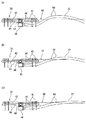
第1の発明によれば、取水ホースがその中に滞留した空気によって水源地の水面から浮き上がったときでも、空気抜き部から空気を放出して、取水ホースを通水可能な状態にすることができる。したがって、従来であれば必要であった多くの人員、設備、時間が節約できる。
12 …堤体
14 …水源池
16 …隧道
18 …給水管路
22 …取水ホース
24 …取水フロート
62 …加圧注水部
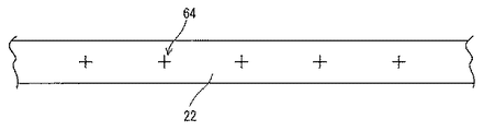
64 …空気抜き孔
66 …水面
68 …シート
72 …ホース(加圧注水部)
Claims (8)
- 堤体で堰き止められた水源池の水を、堤体を挟んで前記水源池とは反対側にある圃場に供給する給水システムであって、
前記水源池に浮かべられ、取水部から前記水源池の水を取り込むフロート、
前記フロートに先端が連結されて前記フロート内に取り込まれた水が送り込まれる取水ホース、および
前記水源池内で前記取水ホースの基端に連結され、前記取水ホースが取水した水を前記圃場に導く給水管路を備え、
前記取水ホースはその中の空気を抜くために形成された空気抜き部を含む、給水システム。 - 前記空気抜き部は、前記取水ホースの前記先端と前記基端との間の中間より前記先端側に形成される、請求項1記載の給水システム。
- 前記空気抜き部は、前記取水ホースに、前記取水ホースの管軸方向に間隔を隔てて形成された複数の空気抜き孔を含む、請求項1または2記載の給水システム。
- 前記取水ホースの外面に設けられて、前記複数の空気抜き孔の対応するものを外面から塞ぐ複数のシートをさらに備える、請求項3記載の給水システム。
- 前記給水管路は前記堤体下を通る給水管路および前記堤体の外で前記給水管路に連結される接続管部を含み、前記水は前記接続管部に設けられた仕切弁を経て前記圃場に給水され、さらに
前記仕切弁より上流側の前記接続管部に形成された加圧注水部を備える、請求項1ないし4のいずれかに記載の給水システム。 - 堤体で堰き止められた水源池の水を、堤体を挟んで前記水源池とは反対側にある圃場に供給するために、前記水源池に浮かべられ、取水部から前記水源池の水を取り込むフロート、前記フロートに先端が連結されて前記フロート内に取り込まれた水が送り込まれる取水ホース、および前記水源池内で前記取水ホースの基端に連結され、前記取水ホースが取水した水を前記圃場に導く給水管路を備える給水システムにおいて、浮上した前記取水ホースを前記水源池の水面下に沈める方法であって、
前記取水ホースに形成した空気抜き部から空気を放出することによって前記取水ホースを沈めるようにした、取水ホースを沈める方法。 - 前記給水管路の下流側から水を加圧注入することによって、前記取水ホース内の滞留空気を前記空気抜き部まで移動させる、請求項6記載の取水ホースを沈める方法。
- 堤体で堰き止められた水源池の水を、堤体を挟んで前記水源池とは反対側にある圃場に供給するために、前記水源池に浮かべられ、取水部から前記水源池の水を取り込むフロート、前記フロートに先端が連結されて前記フロート内に取り込まれた水が送り込まれる取水ホース、および前記水源池内で前記取水ホースの基端に連結され、前記取水ホースが取水した水を前記圃場に導く給水管路を備え、前記給水管路は前記堤体下を通る給水管路および前記堤体の外で前記給水管路に連結される接続管部を含み、前記水は前記接続管部に設けられた仕切弁を経て前記圃場に給水される給水システムにおいて、浮上した前記取水ホースを前記水源池の水面下に沈める方法であって、
前記仕切弁より上流側の前記接続管部において加圧注水することによって前記取水ホースを沈めるようにした、取水ホースを沈める方法。
Priority Applications (1)
| Application Number | Priority Date | Filing Date | Title |
|---|---|---|---|
| JP2016100703A JP6633451B2 (ja) | 2016-05-19 | 2016-05-19 | 給水システム |
Applications Claiming Priority (1)
| Application Number | Priority Date | Filing Date | Title |
|---|---|---|---|
| JP2016100703A JP6633451B2 (ja) | 2016-05-19 | 2016-05-19 | 給水システム |
Publications (2)
| Publication Number | Publication Date |
|---|---|
| JP2017205073A true JP2017205073A (ja) | 2017-11-24 |
| JP6633451B2 JP6633451B2 (ja) | 2020-01-22 |
Family
ID=60414724
Family Applications (1)
| Application Number | Title | Priority Date | Filing Date |
|---|---|---|---|
| JP2016100703A Active JP6633451B2 (ja) | 2016-05-19 | 2016-05-19 | 給水システム |
Country Status (1)
| Country | Link |
|---|---|
| JP (1) | JP6633451B2 (ja) |
Citations (8)
| Publication number | Priority date | Publication date | Assignee | Title |
|---|---|---|---|---|
| JPS5779270A (en) * | 1980-10-31 | 1982-05-18 | Kawasaki Heavy Ind Ltd | Construction of cold water intake pipes in marine differential temperature power plant |
| JPH0359582U (ja) * | 1989-10-14 | 1991-06-12 | ||
| JPH084657A (ja) * | 1994-06-21 | 1996-01-09 | Taiyo Plant Kk | 深層水等の取水装置 |
| JP2003176555A (ja) * | 2001-09-17 | 2003-06-24 | Hotsuma Kobo Kk | 波浪退避型海洋深層水簡易取水システムと事業化モデル |
| JP2004278604A (ja) * | 2003-03-14 | 2004-10-07 | Ohbayashi Corp | 取水管 |
| US7222638B1 (en) * | 2005-05-27 | 2007-05-29 | Kau-Fui Vincent Wong | Vortex minimizing fluid gathering and transferring apparatus |
| JP2013204278A (ja) * | 2012-03-28 | 2013-10-07 | Paddy Research Co Ltd | サイホン式取水システム、抜気部接続継手および通水開始方法 |
| JP2016067339A (ja) * | 2014-10-02 | 2016-05-09 | クボタシーアイ株式会社 | 取水システム |
-
2016
- 2016-05-19 JP JP2016100703A patent/JP6633451B2/ja active Active
Patent Citations (8)
| Publication number | Priority date | Publication date | Assignee | Title |
|---|---|---|---|---|
| JPS5779270A (en) * | 1980-10-31 | 1982-05-18 | Kawasaki Heavy Ind Ltd | Construction of cold water intake pipes in marine differential temperature power plant |
| JPH0359582U (ja) * | 1989-10-14 | 1991-06-12 | ||
| JPH084657A (ja) * | 1994-06-21 | 1996-01-09 | Taiyo Plant Kk | 深層水等の取水装置 |
| JP2003176555A (ja) * | 2001-09-17 | 2003-06-24 | Hotsuma Kobo Kk | 波浪退避型海洋深層水簡易取水システムと事業化モデル |
| JP2004278604A (ja) * | 2003-03-14 | 2004-10-07 | Ohbayashi Corp | 取水管 |
| US7222638B1 (en) * | 2005-05-27 | 2007-05-29 | Kau-Fui Vincent Wong | Vortex minimizing fluid gathering and transferring apparatus |
| JP2013204278A (ja) * | 2012-03-28 | 2013-10-07 | Paddy Research Co Ltd | サイホン式取水システム、抜気部接続継手および通水開始方法 |
| JP2016067339A (ja) * | 2014-10-02 | 2016-05-09 | クボタシーアイ株式会社 | 取水システム |
Also Published As
| Publication number | Publication date |
|---|---|
| JP6633451B2 (ja) | 2020-01-22 |
Similar Documents
| Publication | Publication Date | Title |
|---|---|---|
| CN201162696Y (zh) | 漂浮移动式水泵吸水装置 | |
| CN110053730A (zh) | 半潜式平台及其压载系统 | |
| US3822715A (en) | Irrigation siphon apparatus | |
| CN201794082U (zh) | 局部深基坑降排水装置 | |
| JP3958170B2 (ja) | 堤体及び構造物の保護設備 | |
| CN116513384A (zh) | 一种水上浮动平台装置及其安装方法 | |
| CN208844617U (zh) | 水下支撑半漂浮式沉管隧道 | |
| JP6633451B2 (ja) | 給水システム | |
| CN102747722A (zh) | 地连墙接合缝注浆补漏施工方法及其膨胀胶塞 | |
| KR102237058B1 (ko) | 암반층 차수용 합성파일 차수벽체 시공방법 | |
| TWI267575B (en) | Method for constituting a vertical well in water, vertical well in water, method for connection of a vertical well and a horizontal well, and construction of a well | |
| JP3215231U (ja) | 治水システム | |
| JP5269541B2 (ja) | 通船ゲート | |
| JP6382053B2 (ja) | 取水システム | |
| CN112982462B (zh) | 一种混凝土构件大孔径带压水封堵施工方法 | |
| CN213358768U (zh) | 尾矿库回水井取水装置 | |
| TW201544660A (zh) | 深層海洋水引水方法及引水隧道系統 | |
| CN206376246U (zh) | 用于管涌排险的引流与加固装置 | |
| KR101674417B1 (ko) | 사이폰 현상을 이용한 배수장치 | |
| CN215252971U (zh) | 一种辅助地锚安装的地下水排放系统 | |
| KR101705945B1 (ko) | 수중 가물막이 시공방법 | |
| JP4181595B2 (ja) | ダムのしゅんせつ装置 | |
| CN112031070A (zh) | 一种头部采用立柱和浮筒定位的活动式进水口 | |
| CN221218868U (zh) | 一种降水井封堵结构 | |
| CN206859171U (zh) | 一种土工膜底排气出口装置 |
Legal Events
| Date | Code | Title | Description |
|---|---|---|---|
| A625 | Written request for application examination (by other person) |
Free format text: JAPANESE INTERMEDIATE CODE: A625 Effective date: 20181217 |
|
| A977 | Report on retrieval |
Free format text: JAPANESE INTERMEDIATE CODE: A971007 Effective date: 20190808 |
|
| A131 | Notification of reasons for refusal |
Free format text: JAPANESE INTERMEDIATE CODE: A131 Effective date: 20190820 |
|
| A521 | Request for written amendment filed |
Free format text: JAPANESE INTERMEDIATE CODE: A523 Effective date: 20191009 |
|
| TRDD | Decision of grant or rejection written | ||
| A01 | Written decision to grant a patent or to grant a registration (utility model) |
Free format text: JAPANESE INTERMEDIATE CODE: A01 Effective date: 20191126 |
|
| A61 | First payment of annual fees (during grant procedure) |
Free format text: JAPANESE INTERMEDIATE CODE: A61 Effective date: 20191212 |
|
| R150 | Certificate of patent or registration of utility model |
Ref document number: 6633451 Country of ref document: JP Free format text: JAPANESE INTERMEDIATE CODE: R150 |