JP2017207181A - Speed change gear - Google Patents

Speed change gear Download PDF

Info

Publication number
JP2017207181A
JP2017207181A JP2016101491A JP2016101491A JP2017207181A JP 2017207181 A JP2017207181 A JP 2017207181A JP 2016101491 A JP2016101491 A JP 2016101491A JP 2016101491 A JP2016101491 A JP 2016101491A JP 2017207181 A JP2017207181 A JP 2017207181A
Authority
JP
Japan
Prior art keywords
gear
guide pin
transmission
dog
hub
Prior art date
Legal status (The legal status is an assumption and is not a legal conclusion. Google has not performed a legal analysis and makes no representation as to the accuracy of the status listed.)
Pending
Application number
JP2016101491A
Other languages
Japanese (ja)
Inventor
和徳 秋山
Kazunori Akiyama
和徳 秋山
真二 藤本
Shinji Fujimoto
真二 藤本
Current Assignee (The listed assignees may be inaccurate. Google has not performed a legal analysis and makes no representation or warranty as to the accuracy of the list.)
Honda Motor Co Ltd
Original Assignee
Honda Motor Co Ltd
Priority date (The priority date is an assumption and is not a legal conclusion. Google has not performed a legal analysis and makes no representation as to the accuracy of the date listed.)
Filing date
Publication date
Application filed by Honda Motor Co Ltd filed Critical Honda Motor Co Ltd
Priority to JP2016101491A priority Critical patent/JP2017207181A/en
Priority to CN201710212451.5A priority patent/CN107401584B/en
Publication of JP2017207181A publication Critical patent/JP2017207181A/en
Pending legal-status Critical Current

Links

Images

Classifications

    • FMECHANICAL ENGINEERING; LIGHTING; HEATING; WEAPONS; BLASTING
    • F16ENGINEERING ELEMENTS AND UNITS; GENERAL MEASURES FOR PRODUCING AND MAINTAINING EFFECTIVE FUNCTIONING OF MACHINES OR INSTALLATIONS; THERMAL INSULATION IN GENERAL
    • F16HGEARING
    • F16H3/00Toothed gearings for conveying rotary motion with variable gear ratio or for reversing rotary motion
    • F16H3/02Toothed gearings for conveying rotary motion with variable gear ratio or for reversing rotary motion without gears having orbital motion
    • F16H3/08Toothed gearings for conveying rotary motion with variable gear ratio or for reversing rotary motion without gears having orbital motion exclusively or essentially with continuously meshing gears, that can be disengaged from their shafts
    • F16H3/083Toothed gearings for conveying rotary motion with variable gear ratio or for reversing rotary motion without gears having orbital motion exclusively or essentially with continuously meshing gears, that can be disengaged from their shafts with radially acting and axially controlled clutching members, e.g. sliding keys
    • FMECHANICAL ENGINEERING; LIGHTING; HEATING; WEAPONS; BLASTING
    • F16ENGINEERING ELEMENTS AND UNITS; GENERAL MEASURES FOR PRODUCING AND MAINTAINING EFFECTIVE FUNCTIONING OF MACHINES OR INSTALLATIONS; THERMAL INSULATION IN GENERAL
    • F16DCOUPLINGS FOR TRANSMITTING ROTATION; CLUTCHES; BRAKES
    • F16D11/00Clutches in which the members have interengaging parts
    • F16D11/08Clutches in which the members have interengaging parts actuated by moving a non-rotating part axially
    • F16D11/10Clutches in which the members have interengaging parts actuated by moving a non-rotating part axially with clutching members movable only axially
    • FMECHANICAL ENGINEERING; LIGHTING; HEATING; WEAPONS; BLASTING
    • F16ENGINEERING ELEMENTS AND UNITS; GENERAL MEASURES FOR PRODUCING AND MAINTAINING EFFECTIVE FUNCTIONING OF MACHINES OR INSTALLATIONS; THERMAL INSULATION IN GENERAL
    • F16HGEARING
    • F16H57/00General details of gearing
    • F16H57/02Gearboxes; Mounting gearing therein
    • F16H57/021Shaft support structures, e.g. partition walls, bearing eyes, casing walls or covers with bearings
    • FMECHANICAL ENGINEERING; LIGHTING; HEATING; WEAPONS; BLASTING
    • F16ENGINEERING ELEMENTS AND UNITS; GENERAL MEASURES FOR PRODUCING AND MAINTAINING EFFECTIVE FUNCTIONING OF MACHINES OR INSTALLATIONS; THERMAL INSULATION IN GENERAL
    • F16HGEARING
    • F16H57/00General details of gearing
    • F16H57/02Gearboxes; Mounting gearing therein
    • F16H57/023Mounting or installation of gears or shafts in the gearboxes, e.g. methods or means for assembly
    • FMECHANICAL ENGINEERING; LIGHTING; HEATING; WEAPONS; BLASTING
    • F16ENGINEERING ELEMENTS AND UNITS; GENERAL MEASURES FOR PRODUCING AND MAINTAINING EFFECTIVE FUNCTIONING OF MACHINES OR INSTALLATIONS; THERMAL INSULATION IN GENERAL
    • F16HGEARING
    • F16H63/00Control outputs from the control unit to change-speed- or reversing-gearings for conveying rotary motion or to other devices than the final output mechanism
    • F16H63/02Final output mechanisms therefor; Actuating means for the final output mechanisms
    • F16H63/30Constructional features of the final output mechanisms
    • F16H63/34Locking or disabling mechanisms
    • F16H63/3416Parking lock mechanisms or brakes in the transmission
    • FMECHANICAL ENGINEERING; LIGHTING; HEATING; WEAPONS; BLASTING
    • F16ENGINEERING ELEMENTS AND UNITS; GENERAL MEASURES FOR PRODUCING AND MAINTAINING EFFECTIVE FUNCTIONING OF MACHINES OR INSTALLATIONS; THERMAL INSULATION IN GENERAL
    • F16HGEARING
    • F16H2200/00Transmissions for multiple ratios
    • F16H2200/003Transmissions for multiple ratios characterised by the number of forward speeds
    • F16H2200/006Transmissions for multiple ratios characterised by the number of forward speeds the gear ratios comprising eight forward speeds

Landscapes

  • Engineering & Computer Science (AREA)
  • General Engineering & Computer Science (AREA)
  • Mechanical Engineering (AREA)
  • Mechanical Operated Clutches (AREA)
  • Structure Of Transmissions (AREA)
  • General Details Of Gearings (AREA)

Abstract

PROBLEM TO BE SOLVED: To provide a speed change gear capable of reducing stress generated at a guide pin engaging a hub and a movable ring with each other.SOLUTION: A speed change gear 1 comprises: a hub HB1 which rotates integrally with a rotary shaft 12; a movable ring DR1 which is provided at a periphery of the hub HB1 movably in an axial direction, and has dog teeth D1; a speed changing gear 22 which is provided relatively rotatably to the rotary shaft 12, and has dog teeth D3 opposed to the dog teeth D1; and a dog operation device which operates the movable ring DR1 from a neutral position to an in-gear position. The hub HB1 has a guide groove extending in an axial direction on an outer peripheral surface, and the movable ring DR1 has a guide pin in a substantially columnar shape which has one end part inserted into a recessed part provided on an inner peripheral surface rotatably through lubricating oil and also has the other end part engaging the guide groove.SELECTED DRAWING: Figure 1

Description

本発明は、ドグクラッチを介して変速段を確立する変速機に関する。   The present invention relates to a transmission that establishes a gear position via a dog clutch.

従来より、クラッチカムリングの周囲にクラッチリングを軸方向に移動可能に支持し、クラッチリングの移動に応じて、クラッチリングの側面に設けられたドグ歯と変速ギヤに設けられたドグ歯とを噛合する、または噛合を解除するようにした変速機が知られている(例えば特許文献1参照)。この特許文献1記載の変速機では、クラッチリングの内周面から突設されたカム突部を、クラッチカムリングの外周面のカム溝に係合し、カム突部を介してクラッチカムリングのトルクをクラッチリングに伝達するとともに、変速時においてカム突部をカム溝に沿って摺動させながらクラッチリングを軸方向に移動させる。   Conventionally, the clutch ring is supported around the clutch cam ring so as to be movable in the axial direction, and the dog teeth provided on the side surface of the clutch ring and the dog teeth provided on the transmission gear are engaged according to the movement of the clutch ring. There is known a transmission that performs or releases meshing (see, for example, Patent Document 1). In the transmission described in Patent Document 1, a cam protrusion projecting from the inner peripheral surface of the clutch ring is engaged with a cam groove on the outer peripheral surface of the clutch cam ring, and torque of the clutch cam ring is generated via the cam protrusion. While transmitting to the clutch ring, the clutch ring is moved in the axial direction while sliding the cam projection along the cam groove at the time of shifting.

特許第5707119号公報Japanese Patent No. 5707119

しかしながら、上記特許文献1記載の装置では、クラッチカムリングのトルクが作用するカム突部を変速時にカム溝に沿って摺動させるため、摺動抵抗が大きく、カム突部が破損するおそれがある。   However, in the apparatus described in Patent Document 1, since the cam protrusion on which the torque of the clutch cam ring acts is slid along the cam groove at the time of shifting, the sliding resistance is large and the cam protrusion may be damaged.

本発明の一態様である変速機は、軸線を中心に回転する回転体と、回転体に対し軸方向に相対移動可能かつ回転体と一体に回転可能に設けられ、第1ドグ歯を有する可動リングと、回転体に対し相対回転可能に設けられ、第1ドグ歯に対向した第2ドグ歯を有する変速用ギヤと、第1ドグ歯が第2ドグ歯から離間した中立位置から第1ドグ歯が第2ドグ歯に噛合するインギヤ位置にかけて可動リングを操作するドグ操作装置と、を備え、回転体は、外周面に軸方向に延在するガイド溝を有し、可動リングは、一端部が内周面に設けられた凹部に潤滑油を介して回転可能に挿入されるとともに、他端部がガイド溝に係合する略円柱形状のガイドピンを有する。   A transmission according to an aspect of the present invention includes a rotating body that rotates about an axis, a movable body that is relatively movable in the axial direction with respect to the rotating body, and that can rotate integrally with the rotating body, and has a first dog tooth. A ring, a speed change gear provided with a second dog tooth facing the first dog tooth and capable of rotating relative to the rotating body; and a first dog from a neutral position where the first dog tooth is separated from the second dog tooth. A dog operating device that operates the movable ring over the in-gear position where the teeth mesh with the second dog teeth, the rotating body has a guide groove extending in the axial direction on the outer peripheral surface, and the movable ring has one end portion. Is inserted into a recess provided in the inner peripheral surface through lubricating oil, and has a substantially cylindrical guide pin with the other end engaged with the guide groove.

本発明によれば、回転体のガイド溝に係合する略円柱形状のガイドピンの一端部を、可動リングの凹部に潤滑油を介して回転可能に挿入するので、可動リングの軸方向の移動時に、ガイドピンの一端部が凹部内を摺動しながら回転し、他端部がガイド溝に沿って転動する。このため、簡易な構成によりガイドピンに発生する応力を低減することができ、ガイドピンの破損を防止することができる。   According to the present invention, one end portion of the substantially cylindrical guide pin that engages with the guide groove of the rotating body is rotatably inserted into the concave portion of the movable ring via the lubricating oil, so that the movable ring moves in the axial direction. Sometimes, one end of the guide pin rotates while sliding in the recess, and the other end rolls along the guide groove. For this reason, the stress which generate | occur | produces in a guide pin can be reduced with a simple structure, and damage to a guide pin can be prevented.

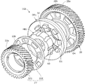
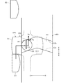
本発明の実施形態に係る変速機の要部構成を示すスケルトン図。The skeleton figure which shows the principal part structure of the transmission which concerns on embodiment of this invention. 図1の変速機に含まれる第1ギヤ結合機構の構成を示す分解斜視図。The disassembled perspective view which shows the structure of the 1st gear coupling mechanism contained in the transmission of FIG. 図1の変速機に含まれる第1ギヤ結合機構の組立て状態を示す変速機の要部断面図。FIG. 2 is a cross-sectional view of a main part of the transmission showing an assembled state of a first gear coupling mechanism included in the transmission of FIG. 1. 図3のIV-IV線に沿って切断した第1ギヤ結合機構の要部構成を拡大して示す断面図。Sectional drawing which expands and shows the principal part structure of the 1st gear coupling mechanism cut | disconnected along the IV-IV line | wire of FIG. 第1ギヤ結合機構が中立状態にある場合のガイド溝とガイドピンとの位置関係を示す図。The figure which shows the positional relationship of a guide groove and a guide pin in case a 1st gear coupling mechanism exists in a neutral state. 加速走行時における第1ギヤ結合機構のトルクの伝達経路を示す図。The figure which shows the transmission path of the torque of the 1st gear coupling mechanism at the time of acceleration driving | running | working. 減速走行時における第1ギヤ結合機構のトルクの伝達径路を示す図。The figure which shows the transmission path of the torque of the 1st gear coupling mechanism at the time of deceleration driving | running | working. 図1の変形例を示す図。The figure which shows the modification of FIG.

以下、図1〜図8を参照して本発明の実施形態について説明する。図1は、本発明の実施形態に係る変速機の要部構成を示すスケルトン図である。この変速機1は、例えばハイブリッド車両に搭載される。ハイブリッド車両は、エンジン2と電動機3とを備える。   Hereinafter, embodiments of the present invention will be described with reference to FIGS. FIG. 1 is a skeleton diagram showing a main configuration of a transmission according to an embodiment of the present invention. The transmission 1 is mounted on, for example, a hybrid vehicle. The hybrid vehicle includes an engine 2 and an electric motor 3.

変速機1は、エンジン2および電動機3の少なくとも一方の回転を速度段に応じた変速比で変速するギヤ機構10と、エンジン2のトルクをギヤ機構10に伝達または非伝達するクラッチ機構Cとを有する。ギヤ機構10を介して出力されたトルクは、図示しない差動ギヤ機構、駆動軸等を介して駆動輪に伝達され、これにより車両が走行する。   The transmission 1 includes a gear mechanism 10 that changes the rotation of at least one of the engine 2 and the electric motor 3 at a speed ratio corresponding to the speed stage, and a clutch mechanism C that transmits or does not transmit the torque of the engine 2 to the gear mechanism 10. Have. Torque output via the gear mechanism 10 is transmitted to drive wheels via a differential gear mechanism, a drive shaft, and the like (not shown), thereby causing the vehicle to travel.

ギヤ機構10は、互いに略平行に配置され、それぞれが回転可能に支持された複数の回転軸、すなわち第1主入力軸11と第2主入力軸12と副入力軸13と出力軸14とリバース軸15とを有する。第2主入力軸12は、第1主入力軸11と同軸上にかつ第1主入力軸11を包囲するように中空に形成される。変速機1は、例えば前進8速、後進1速の自動変速機である。クラッチ機構Cは、乾式クラッチにより構成された第1クラッチC1と第2クラッチC2とを有する。なお、乾式クラッチに代えて湿式クラッチ(例えば湿式多板クラッチ)を用いることもできる。   The gear mechanism 10 is arranged substantially parallel to each other, and each of the plurality of rotation shafts is rotatably supported, that is, the first main input shaft 11, the second main input shaft 12, the sub input shaft 13, the output shaft 14, and the reverse. And a shaft 15. The second main input shaft 12 is formed so as to be coaxial with the first main input shaft 11 and so as to surround the first main input shaft 11. The transmission 1 is, for example, an automatic transmission with 8 forward speeds and 1 reverse speed. The clutch mechanism C includes a first clutch C1 and a second clutch C2 that are configured by a dry clutch. A wet clutch (for example, a wet multi-plate clutch) can be used instead of the dry clutch.

電動機3は、例えば3相のDCブラシレスモータにより構成され、図示しない電動機3のハウジング内に回転可能に支持されたロータ3aと、ロータ3aの周囲に配置され、ハウジングに固定されたステータ3bとを有する。第1主入力軸11の一端部は、電動機3のロータ3aに接続され、第1主入力軸11はロータ3aと一体に回転可能である。   The electric motor 3 is composed of, for example, a three-phase DC brushless motor, and includes a rotor 3a rotatably supported in a housing of the electric motor 3 (not shown), and a stator 3b disposed around the rotor 3a and fixed to the housing. Have. One end of the first main input shaft 11 is connected to the rotor 3a of the electric motor 3, and the first main input shaft 11 can rotate integrally with the rotor 3a.

第1主入力軸11の他端部は、第1クラッチC1を介してエンジン2の出力軸2aに接続され、第1クラッチC1の断接に応じて第1主入力軸11と出力軸2aとが結合または遮断される。すなわち、第1クラッチC1が接続すると、第1主入力軸11と出力軸2aとが結合され、第1主入力軸11にエンジン2からのトルクを入力可能となる。一方、第1クラッチC1が遮断すると、第1主入力軸11と出力軸2aとが遮断され、エンジン2からのトルク入力が不能となる。   The other end of the first main input shaft 11 is connected to the output shaft 2a of the engine 2 via the first clutch C1, and the first main input shaft 11 and the output shaft 2a are connected according to the connection / disconnection of the first clutch C1. Are bound or blocked. That is, when the first clutch C1 is connected, the first main input shaft 11 and the output shaft 2a are coupled, and the torque from the engine 2 can be input to the first main input shaft 11. On the other hand, when the first clutch C1 is disconnected, the first main input shaft 11 and the output shaft 2a are disconnected, and torque input from the engine 2 becomes impossible.

さらに第1主入力軸の11の他端部は、第2クラッチC2を介して第2主入力軸12の一端部に接続され、第2クラッチC2の断接に応じて第1主入力軸11と第2主入力軸12とが結合または遮断される。すなわち、第2クラッチC2が接続すると、第1主入力軸11と第2主入力軸12とが結合され、第2クラッチC2が遮断すると、第1主入力軸11と第2主入力軸12とが遮断される。例えば第1クラッチC1と第2クラッチC2の双方が接続すると、第2主入力軸12にエンジン2からのトルクが入力可能となる。第2クラッチC2のみが接続されると、第2主入力軸12に電動機3のトルクが入力可能となる。   Further, the other end portion of the first main input shaft 11 is connected to one end portion of the second main input shaft 12 via the second clutch C2, and the first main input shaft 11 is connected according to the connection / disconnection of the second clutch C2. And the second main input shaft 12 are coupled or disconnected. That is, when the second clutch C2 is connected, the first main input shaft 11 and the second main input shaft 12 are coupled, and when the second clutch C2 is disconnected, the first main input shaft 11 and the second main input shaft 12 are connected. Is cut off. For example, when both the first clutch C 1 and the second clutch C 2 are connected, torque from the engine 2 can be input to the second main input shaft 12. When only the second clutch C <b> 2 is connected, the torque of the electric motor 3 can be input to the second main input shaft 12.

なお、本実施形態の変速機1のクラッチ機構Cは、一対のクラッチC1,C2を有するが、これは入力軸11,12とエンジン2および電動機3との接続を切り換えるためのものである。したがって、クラッチ機構Cは、エンジン2とギヤ機構10または電動機3とギヤ機構10を断接するシングルクラッチと同様の機能を有し、奇数変速段用のクラッチと偶数変速段用のクラッチとそれぞれ有するデュアルクラッチ(ツインクラッチ)とは構成が異なる。   The clutch mechanism C of the transmission 1 according to the present embodiment includes a pair of clutches C1 and C2 for switching the connection between the input shafts 11 and 12 and the engine 2 and the electric motor 3. Therefore, the clutch mechanism C has a function similar to that of a single clutch that connects and disconnects the engine 2 and the gear mechanism 10 or the electric motor 3 and the gear mechanism 10, and has a clutch for odd-numbered gears and a clutch for even-numbered gears. The configuration is different from the clutch (twin clutch).

第2主入力軸12の周囲には、2速駆動ギヤ22と、8速駆動ギヤ28と、4速駆動ギヤ24と、7速駆動ギヤ27とが、電動機3側からこの順番に配設される。これら駆動ギヤ22,24,27,28は、それぞれ不図示のベアリングを介し第2主入力軸12に対して相対回転可能に支持される。第2主入力軸12には、7速駆動ギヤ27の側方(クラッチ機構C側)にギヤ31が固定される。ギヤ31は、リバース軸15に固定されたギヤ32に噛合する。リバース軸15の周囲には、リバース駆動ギヤ29とパーキングギヤ30とがリバース軸15に対し相対回転可能に支持される。   Around the second main input shaft 12, a 2-speed drive gear 22, an 8-speed drive gear 28, a 4-speed drive gear 24, and a 7-speed drive gear 27 are arranged in this order from the electric motor 3 side. The These drive gears 22, 24, 27, and 28 are supported so as to be relatively rotatable with respect to the second main input shaft 12 via bearings (not shown). A gear 31 is fixed to the second main input shaft 12 on the side (clutch mechanism C side) of the seventh speed drive gear 27. The gear 31 meshes with a gear 32 fixed to the reverse shaft 15. A reverse drive gear 29 and a parking gear 30 are supported around the reverse shaft 15 so as to be rotatable relative to the reverse shaft 15.

なお、本明細書において、回転軸(第2主入力軸12、出力軸14、リバース軸15など)にギヤが固定されるとは、回転軸の外周面にギヤを加工する場合や、回転軸と別体のギヤをスプライン結合等により回転軸に支持する場合、すなわち回転軸に相対回転不能にギヤを設ける場合をいう。   In this specification, the gear is fixed to the rotating shaft (the second main input shaft 12, the output shaft 14, the reverse shaft 15, etc.) when processing the gear on the outer peripheral surface of the rotating shaft, The case where a separate gear is supported on the rotating shaft by spline coupling or the like, that is, the case where the gear is provided on the rotating shaft so as not to be relatively rotatable.

図示は省略するが、ギヤ32は、副入力軸13に固定されたギヤ33に噛合する。これにより第2主入力軸12の回転がギヤ31〜33を介して副入力軸13に伝達され、副入力軸13は第2主入力軸12およびリバース軸15とともに回転する。副入力軸13の周囲には、1速駆動ギヤ21と、6速駆動ギヤ26と、3速駆動ギヤ23と、5速駆動ギヤ25とが、電動機3側からこの順番に配設される。これら駆動ギヤ21,23,25,26は、それぞれ不図示のベアリングを介し副入力軸13に対して相対回転可能に支持される。   Although not shown, the gear 32 meshes with a gear 33 fixed to the sub input shaft 13. Thereby, the rotation of the second main input shaft 12 is transmitted to the sub input shaft 13 via the gears 31 to 33, and the sub input shaft 13 rotates together with the second main input shaft 12 and the reverse shaft 15. Around the auxiliary input shaft 13, a first speed drive gear 21, a sixth speed drive gear 26, a third speed drive gear 23, and a fifth speed drive gear 25 are arranged in this order from the electric motor 3 side. These drive gears 21, 23, 25, and 26 are supported so as to be relatively rotatable with respect to the auxiliary input shaft 13 via bearings (not shown).

出力軸14には、1−2速従動ギヤ41と、6−8速従動ギヤ42と、3−4速従動ギヤ43と、5−7速従動ギヤ44と、ファイナルギヤ45とが、電動機3側からこの順番に固定される。1−2速従動ギヤ41は、1速駆動ギヤ21と2速駆動ギヤ22とにそれぞれ噛合する。なお、図示は省略するが、1−2速従動ギヤ41はリバース駆動ギヤ33にも噛合する。6−8速従動ギヤ42は、6速駆動ギヤ26と8速駆動ギヤ28とにそれぞれ噛合する。3−4速従動ギヤ43は、3速駆動ギヤ23と4速駆動ギヤ24とにそれぞれ噛合する。5−7速従動ギヤ44は、5速駆動ギヤ25と7速駆動ギヤ27とにそれぞれ噛合する。   The output shaft 14 includes a 1-2 speed driven gear 41, a 6-8 speed driven gear 42, a 3-4 speed driven gear 43, a 5-7 speed driven gear 44, and a final gear 45. It is fixed in this order from the side. The first-second driven gear 41 meshes with the first-speed drive gear 21 and the second-speed drive gear 22, respectively. Although illustration is omitted, the 1-2 speed driven gear 41 also meshes with the reverse drive gear 33. The 6-8 speed driven gear 42 meshes with the 6 speed drive gear 26 and the 8 speed drive gear 28, respectively. The 3-4 speed driven gear 43 meshes with the 3rd speed drive gear 23 and the 4th speed drive gear 24, respectively. The 5-7 speed driven gear 44 meshes with the 5th speed drive gear 25 and the 7th speed drive gear 27, respectively.

パーキングギヤ30は、図示しないパーキングギヤ機構の係合爪と噛合可能に構成される。パーキングギヤ機構の作動に応じてパーキングギヤ30に係合爪が係合すると、ギヤ機構10がロックされ、係合爪の係合が解除されると、ギヤ機構10がアンロックされる。変速機1のトルクは、ファイナルギヤ45を介して、図示しない差動ギヤ機構に出力される。   The parking gear 30 is configured to engage with an engaging claw of a parking gear mechanism (not shown). When the engagement claw is engaged with the parking gear 30 according to the operation of the parking gear mechanism, the gear mechanism 10 is locked, and when the engagement of the engagement claw is released, the gear mechanism 10 is unlocked. The torque of the transmission 1 is output to a differential gear mechanism (not shown) via the final gear 45.

変速機1は、ドグ歯を介して駆動ギヤ21〜29をトルク伝達用の回転軸に結合する複数のギヤ結合機構(ドグクラッチ)を有する。すなわち、2速駆動ギヤ22または8速駆動ギヤ28を第2主入力軸12に結合する第1ギヤ結合機構1GEと、4速駆動ギヤ24または7速駆動ギヤ27を第2主入力軸12に結合する第2ギヤ結合機構2GEと、1速駆動ギヤ21または6速駆動ギヤ26を副入力軸13に結合する第3ギヤ結合機構3GEと、3速駆動ギヤ23または5速駆動ギヤ25を副入力軸13に結合する第4ギヤ結合機構4GEと、リバース駆動ギヤ29をリバース軸15に結合する第5ギヤ結合機構5GEとを有する。   The transmission 1 has a plurality of gear coupling mechanisms (dog clutches) that couple the drive gears 21 to 29 to the torque transmission rotary shaft via dog teeth. That is, the first gear coupling mechanism 1GE that couples the second speed drive gear 22 or the eighth speed drive gear 28 to the second main input shaft 12, and the fourth speed drive gear 24 or the seventh speed drive gear 27 to the second main input shaft 12. The second gear coupling mechanism 2GE to be coupled, the third gear coupling mechanism 3GE for coupling the first speed driving gear 21 or the sixth speed driving gear 26 to the sub input shaft 13, and the third speed driving gear 23 or the fifth speed driving gear 25 to the sub A fourth gear coupling mechanism 4GE coupled to the input shaft 13 and a fifth gear coupling mechanism 5GE coupling the reverse drive gear 29 to the reverse shaft 15 are provided.

図2は、第1ギヤ結合機構1GEの構成を示す分解斜視図であり、図3は、第1ギヤ結合機構1GEの組立て状態を示す変速機1の要部断面図である。図2,3に示すように、第1ギヤ結合機構1GEは、2速駆動ギヤ22と8速駆動ギヤ28との間に配置され、第2主入力軸12に固定されて、軸線CL0を中心に回転するハブHB1と、ハブHB1の外周面に沿って軸方向(図3の矢印AB方向)に移動可能に支持された可動リングDR1とを有する。   FIG. 2 is an exploded perspective view showing the configuration of the first gear coupling mechanism 1GE, and FIG. 3 is a cross-sectional view of the main part of the transmission 1 showing the assembled state of the first gear coupling mechanism 1GE. As shown in FIGS. 2 and 3, the first gear coupling mechanism 1GE is disposed between the second speed drive gear 22 and the eighth speed drive gear 28, fixed to the second main input shaft 12, and centered on the axis line CL0. And a movable ring DR1 supported so as to be movable in the axial direction (the arrow AB direction in FIG. 3) along the outer peripheral surface of the hub HB1.

より具体的には、可動リングDR1の内周面には、径方向内側に向けて周方向複数の略円柱形状のガイドピン50が突設され、各ガイドピン50に対応してハブHB1の外周面には、軸方向一端面から他端面にかけて周方向複数の略V字状のガイド溝60が設けられる。ガイドピン50はガイド溝60に係合し、ガイドピン50はガイド溝60にガイドされながら可動リングDR1と一体に軸方向(図3の矢印AB方向)に移動する。可動リングDR1の軸方向一端面には、周方向等間隔にドグ歯D1が突設され、軸方向他端面には、周方向等間隔にドグ歯D2が突設される。   More specifically, a plurality of substantially cylindrical guide pins 50 in the circumferential direction protrude from the inner peripheral surface of the movable ring DR1 radially inward, and the outer periphery of the hub HB1 corresponds to each guide pin 50. A plurality of substantially V-shaped guide grooves 60 in the circumferential direction are provided on the surface from one axial end surface to the other end surface. The guide pin 50 engages with the guide groove 60, and the guide pin 50 moves in the axial direction (direction of arrow AB in FIG. 3) integrally with the movable ring DR1 while being guided by the guide groove 60. Dog teeth D1 project from the one end surface in the axial direction of the movable ring DR1 at equal intervals in the circumferential direction, and dog teeth D2 project from the other end surface in the axial direction at equal intervals in the circumferential direction.

2速駆動ギヤ22は、外周面に形成された変速ギヤ22aと、ドグ歯D1に対向して軸方向端部に設けられたドグ歯D3とを有する。より具体的には、2速駆動ギヤ22は、外周面に変速ギヤ22aが形成されたギヤ本体221と、ギヤ本体221の可動リングDR1側の端部にスプライン結合により取り付けられた噛合リング222とを一体に有する。噛合リング222には、可動リングDR1のドグ歯D1に対応して周方向複数の開口部22bが設けられ、2速駆動ギヤ22(噛合リング222)の軸方向端面は周方向に凹凸状に形成される。これにより2速駆動ギヤ22の軸方向端部に、ドグ歯D1に対向してドグ歯D3が設けられる。   The second-speed drive gear 22 has a transmission gear 22a formed on the outer peripheral surface, and dog teeth D3 provided at the end in the axial direction facing the dog teeth D1. More specifically, the second-speed drive gear 22 includes a gear main body 221 having a transmission gear 22a formed on the outer peripheral surface, and a meshing ring 222 attached to the end of the gear main body 221 on the movable ring DR1 side by spline coupling. Are integrated. The meshing ring 222 is provided with a plurality of openings 22b in the circumferential direction corresponding to the dog teeth D1 of the movable ring DR1, and the axial end surface of the second speed drive gear 22 (meshing ring 222) is formed in an uneven shape in the circumferential direction. Is done. As a result, the dog tooth D3 is provided at the axial end of the second-speed drive gear 22 so as to face the dog tooth D1.

8速駆動ギヤ28は、外周面に形成された変速ギヤ28aと、ドグ歯D2に対向して軸方向端部に設けられたドグ歯D4とを有する。より具体的には、8速駆動ギヤ28には、可動リングDR1のドグ歯D2に対応して周方向複数の開口部28bが設けられ、8速駆動ギヤ28の軸方向端面は周方向に凹凸状に形成される。これにより8速駆動ギヤ28の軸方向端部に、ドグ歯D2に対向してドグ歯D4が設けられる。   The 8-speed drive gear 28 has a transmission gear 28a formed on the outer peripheral surface, and dog teeth D4 provided at the end in the axial direction facing the dog teeth D2. More specifically, the 8-speed drive gear 28 is provided with a plurality of circumferential openings 28b corresponding to the dog teeth D2 of the movable ring DR1, and the axial end surface of the 8-speed drive gear 28 is uneven in the circumferential direction. It is formed in a shape. As a result, dog teeth D4 are provided at the axial ends of the 8-speed drive gear 28 so as to face the dog teeth D2.

図3では、可動リングDR1のドグ歯D1,D2が2速駆動ギヤ22および8速駆動ギヤ28のいずれのドグ歯D3,D4にも噛合しておらず、可動リングDR1は中立位置に位置し、第1ギヤ結合機構1GEは中立状態にある。この状態から可動リングDR1が矢印A方向のインギヤ位置に移動してドグ歯D1がドグ歯D3に噛合すると、2速駆動ギヤ22が第2主入力軸12に結合し、第1ギヤ結合機構1GEはギヤ結合状態となる。また、可動リングDR1が矢印B方向のインギヤ位置に移動してドグ歯D2がドグ歯D4に噛合すると、8速駆動ギヤ28が第2主入力軸12に結合し、第1ギヤ結合機構1GEはギヤ結合状態となる。   In FIG. 3, the dog teeth D1 and D2 of the movable ring DR1 are not meshed with the dog teeth D3 and D4 of the second speed drive gear 22 and the eighth speed drive gear 28, and the movable ring DR1 is located at the neutral position. The first gear coupling mechanism 1GE is in a neutral state. From this state, when the movable ring DR1 moves to the in-gear position in the direction of arrow A and the dog teeth D1 mesh with the dog teeth D3, the second-speed drive gear 22 is coupled to the second main input shaft 12, and the first gear coupling mechanism 1GE. Is in a gear-coupled state. When the movable ring DR1 moves to the in-gear position in the direction of arrow B and the dog tooth D2 meshes with the dog tooth D4, the 8-speed drive gear 28 is coupled to the second main input shaft 12, and the first gear coupling mechanism 1GE is The gear is connected.

可動リングDR1は、ドグ操作装置40により中立位置からインギヤ位置またはインギヤ位置から中立位置に操作される。図示は省略するが、ドグ操作装置40は、可動リングDR1を駆動するアクチュエータ(電動モータなど)を有し、アクチュエータはコントローラからの制御信号により駆動制御される。例えばコントローラは、車速とアクセルペダルの踏み込み量とに基づき車両の要求トルクを算出し、要求トルクに応じた変速段となるようにアクチュエータを制御する。   The movable ring DR1 is operated by the dog operating device 40 from the neutral position to the in-gear position or from the in-gear position to the neutral position. Although not shown, the dog operating device 40 includes an actuator (such as an electric motor) that drives the movable ring DR1, and the actuator is driven and controlled by a control signal from the controller. For example, the controller calculates the required torque of the vehicle based on the vehicle speed and the amount of depression of the accelerator pedal, and controls the actuator so as to achieve a shift stage according to the required torque.

図1において、第1ギヤ結合機構1GEを介して2速駆動ギヤ22が第2主入力軸12に結合すると、第2主入力軸12の回転が2速駆動ギヤ22、1−2速従動ギヤ41を介して出力軸14に伝達され、2速段が確立する。第1ギヤ結合機構1GEを介して8速駆動ギヤ28が第2主入力軸12に結合すると、第2主入力軸12の回転が8速駆動ギヤ28、6−8速従動ギヤ42を介して出力軸14に伝達され、8速段が確立する。   In FIG. 1, when the second speed drive gear 22 is coupled to the second main input shaft 12 via the first gear coupling mechanism 1GE, the rotation of the second main input shaft 12 is changed to the second speed drive gear 22, 1-2 speed driven gear. Is transmitted to the output shaft 14 via 41, and the second gear is established. When the 8-speed drive gear 28 is coupled to the second main input shaft 12 via the first gear coupling mechanism 1GE, the rotation of the second main input shaft 12 is transmitted via the 8-speed drive gear 28 and the 6-8-speed driven gear 42. Transmission to the output shaft 14 establishes the eighth gear.

詳細な図示は省略するが、他のギヤ結合機構2GE〜5GEも第1ギヤ結合機構1GEと同様に構成される。   Although not shown in detail, the other gear coupling mechanisms 2GE to 5GE are configured in the same manner as the first gear coupling mechanism 1GE.

第2ギヤ結合機構2GEを介して4速駆動ギヤ24が第2主入力軸12に結合すると、第2主入力軸12の回転が4速駆動ギヤ24、3−4速従動ギヤ43を介して出力軸14に伝達され、4速段が確立する。第2ギヤ結合機構2GEを介して7速駆動ギヤ27が第2主入力軸12に結合すると、第2主入力軸12の回転が7速駆動ギヤ27、5−7速従動ギヤ44を介して出力軸14に伝達され、7速段が確立する。   When the fourth speed drive gear 24 is coupled to the second main input shaft 12 via the second gear coupling mechanism 2GE, the rotation of the second main input shaft 12 is transmitted via the fourth speed drive gear 24 and the 3-4 speed driven gear 43. It is transmitted to the output shaft 14 and the fourth gear is established. When the seventh speed drive gear 27 is coupled to the second main input shaft 12 via the second gear coupling mechanism 2GE, the rotation of the second main input shaft 12 is transmitted via the seventh speed drive gear 27 and the 5-7 speed driven gear 44. Transmission to the output shaft 14 establishes the seventh gear.

第3ギヤ結合機構3GEを介して1速駆動ギヤ21が副入力軸13に結合すると、副入力軸13の回転が1速駆動ギヤ21、1−2速従動ギヤ41を介して出力軸14に伝達され、1速段が確立する。第3ギヤ結合機構3GEを介して6速駆動ギヤ26が副入力軸13に結合すると、副入力軸13の回転が6速駆動ギヤ26、6−8速従動ギヤ42を介して出力軸14に伝達され、6速段が確立する。   When the first speed drive gear 21 is coupled to the sub input shaft 13 via the third gear coupling mechanism 3GE, the rotation of the sub input shaft 13 is transferred to the output shaft 14 via the first speed drive gear 21 and the first and second speed driven gear 41. The first gear is established. When the sixth speed drive gear 26 is coupled to the sub input shaft 13 via the third gear coupling mechanism 3GE, the rotation of the sub input shaft 13 is transferred to the output shaft 14 via the sixth speed drive gear 26 and the 6-8 speed driven gear 42. The 6th speed is established.

第4ギヤ結合機構4GEを介して3速駆動ギヤ23が副入力軸13に結合すると、副入力軸13の回転が3速駆動ギヤ23、3−4速従動ギヤ43を介して出力軸14に伝達され、3速段が確立する。第4ギヤ結合機構4GEを介して5速駆動ギヤ25が副入力軸13に結合すると、副入力軸13の回転が5速駆動ギヤ25、5−7速従動ギヤ44を介して出力軸14に伝達され、5速段が確立する。   When the third speed drive gear 23 is coupled to the sub input shaft 13 via the fourth gear coupling mechanism 4GE, the rotation of the sub input shaft 13 is transferred to the output shaft 14 via the third speed drive gear 23 and the 3-4 speed driven gear 43. The third gear is established. When the fifth speed drive gear 25 is coupled to the sub input shaft 13 via the fourth gear coupling mechanism 4GE, the rotation of the sub input shaft 13 is transferred to the output shaft 14 via the fifth speed drive gear 25 and the 5-7 speed driven gear 44. Then, the fifth gear is established.

第5ギヤ結合機構5GEを介してリバース駆動ギヤ29がリバース軸15に結合すると、リバース軸15の回転がリバース駆動ギヤ29、1−2速従動ギヤ41を介して出力軸14に伝達され、後進段が確立する。なお、図示は省略するが、可動リングDR5が軸方向の所定位置に移動すると、パーキングギヤ機構が作動し、パーキングギヤ機構の係合爪がパーキングギヤ30に係合してギヤ機構10がロックされる。   When the reverse drive gear 29 is coupled to the reverse shaft 15 via the fifth gear coupling mechanism 5GE, the rotation of the reverse shaft 15 is transmitted to the output shaft 14 via the reverse drive gear 29 and the first-second driven gear 41, and the reverse drive A stage is established. Although illustration is omitted, when the movable ring DR5 moves to a predetermined position in the axial direction, the parking gear mechanism is activated, the engaging claw of the parking gear mechanism engages with the parking gear 30, and the gear mechanism 10 is locked. The

上述したように、本実施形態では、ギヤ結合機構1GE〜5GEのハブHB1〜HB5と可動リングDR1〜DR5とは、それぞれガイド溝60に係合されたガイドピン50を介してトルク伝達可能に連結される(図2,3)。以下、この点について詳細に説明する。   As described above, in the present embodiment, the hubs HB1 to HB5 and the movable rings DR1 to DR5 of the gear coupling mechanisms 1GE to 5GE are connected to each other through the guide pins 50 engaged with the guide grooves 60 so that torque can be transmitted. (FIGS. 2 and 3). Hereinafter, this point will be described in detail.

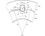
図4は、図3のIV-IV線に沿って切断した第1ギヤ結合機構1GEのハブHB1と可動リングDR1の要部構成を拡大して示す断面図であり、図5は、中立状態におけるガイド溝60とガイドピン50との間の位置関係を示す図である。なお、図示は省略するが、他のギヤ結合機構2GE〜5GEのガイド溝60とガイドピン50の構成も図4,5に示したものと同一である。   FIG. 4 is an enlarged cross-sectional view showing the main components of the hub HB1 and the movable ring DR1 of the first gear coupling mechanism 1GE cut along the line IV-IV in FIG. 3, and FIG. It is a figure which shows the positional relationship between the guide groove 60 and the guide pin 50. FIG. In addition, although illustration is abbreviate | omitted, the structure of the guide groove 60 and the guide pin 50 of other gear coupling mechanisms 2GE-5GE is also the same as what was shown in FIG.

図4に示すように、可動リングDR1の内周面51には円形の有底孔52が設けられ、有底孔52に円柱形状のガイドピン50の一端部が挿入される。有底孔52の直径D1はガイドピン50の直径D0よりも所定長さΔdだけ大きく、有底孔52とガイドピン50との間の隙間53に潤滑油が充填される。このようにガイドピン50を有底孔52に圧入するのではなく、所定長さΔdの隙間53を設けて有底孔52に挿入することで、ガイドピン50は有底孔52から脱落することなく、潤滑油の表面張力により有底孔52に回転可能に保持される。なお、所定長さΔdは、隙間53に潤滑油膜を形成し得る値、例えば数百μm程度に設定される。   As shown in FIG. 4, a circular bottomed hole 52 is provided in the inner peripheral surface 51 of the movable ring DR <b> 1, and one end of a cylindrical guide pin 50 is inserted into the bottomed hole 52. The diameter D1 of the bottomed hole 52 is larger than the diameter D0 of the guide pin 50 by a predetermined length Δd, and the gap 53 between the bottomed hole 52 and the guide pin 50 is filled with lubricating oil. Instead of press-fitting the guide pin 50 into the bottomed hole 52 in this way, the guide pin 50 is dropped from the bottomed hole 52 by inserting the gap 53 having a predetermined length Δd into the bottomed hole 52. Instead, it is rotatably held in the bottomed hole 52 by the surface tension of the lubricating oil. The predetermined length Δd is set to a value that can form a lubricating oil film in the gap 53, for example, about several hundred μm.

図5には、車両の前進走行時および後進走行時におけるハブHB1の回転方向をそれぞれ矢印FおよびRで示すとともに、軸方向に沿った可動リングDR1の移動方向を図3と同様、矢印ABで示す。図5に示すように、ハブHB1の外周面61のガイド溝60は、互いに対向する一対の側面62、すなわち矢印R方向側の側面62aと、矢印F方向側の側面62bとを有する。   In FIG. 5, the rotation direction of the hub HB1 during forward traveling and reverse traveling of the vehicle is indicated by arrows F and R, respectively, and the moving direction of the movable ring DR1 along the axial direction is indicated by the arrow AB as in FIG. Show. As shown in FIG. 5, the guide groove 60 of the outer peripheral surface 61 of the hub HB1 has a pair of side surfaces 62 facing each other, that is, a side surface 62a on the arrow R direction side and a side surface 62b on the arrow F direction side.

ガイド溝60は、ハブHB1の軸方向(AB方向)の全長にわたって一方の側面62aから他方の側面62bまでの長さ(溝幅L1)が一定となり、かつ、ハブHB1の軸方向長さL0の中間を通る軸線CL1に対して対称に形成される。軸線CL1の両側の一対の側面62bのなす角θは180°より小さい。溝幅L1は、ガイドピン50の直径D0よりも大きく、さらに有底孔52の直径D1よりも大きい(図4参照)。したがって、ガイド溝60とガイドピン50との間には、隙間53よりも大きな隙間63が形成される。   The guide groove 60 has a constant length (groove width L1) from one side surface 62a to the other side surface 62b over the entire length in the axial direction (AB direction) of the hub HB1, and the axial length L0 of the hub HB1. It is formed symmetrically with respect to the axis CL1 passing through the middle. An angle θ formed by the pair of side surfaces 62b on both sides of the axis CL1 is smaller than 180 °. The groove width L1 is larger than the diameter D0 of the guide pin 50 and further larger than the diameter D1 of the bottomed hole 52 (see FIG. 4). Therefore, a gap 63 larger than the gap 53 is formed between the guide groove 60 and the guide pin 50.

図4に示すように、ハブHB1が矢印A方向に回転すると、可動リングDR1にガイドピン50を介してトルクが作用し、可動リングDR1がハブHB1とともに回転する。このとき、ガイド溝60の側面62aからガイドピン50に押圧力F1が作用し、ガイドピン50から有底孔52の周面に押圧力F2が作用する。なお、図4は、加速走行時の押圧力F1,F2の向きを示しており、減速走行時には可動リングDR1からハブHB1にトルクが作用するため、押圧力F1,F2の向きが反対となる。   As shown in FIG. 4, when the hub HB1 rotates in the direction of arrow A, torque acts on the movable ring DR1 via the guide pin 50, and the movable ring DR1 rotates with the hub HB1. At this time, a pressing force F1 acts on the guide pin 50 from the side surface 62a of the guide groove 60, and a pressing force F2 acts on the peripheral surface of the bottomed hole 52 from the guide pin 50. FIG. 4 shows the directions of the pressing forces F1 and F2 during acceleration traveling. Since torque acts on the hub HB1 from the movable ring DR1 during deceleration traveling, the directions of the pressing forces F1 and F2 are opposite.

押圧力F1,F2は、ガイドピン50とガイド溝60との接触面S1、およびガイドピン50と有底孔52との接触面S2にそれぞれ作用する。ハブHB1の回転中心である軸線CL0から接触面S1の径方向中間位置までの距離R1は、軸線CL0から接触面S2の径方向中間位置までの距離R2よりも短い(R1<R2)。このため、接触面S1,S2に作用するトルクは互いに等しい(R1・F1=R2・F2)ことから、押圧力F2は押圧力F1よりも小さい(F1>F2)。   The pressing forces F1 and F2 act on the contact surface S1 between the guide pin 50 and the guide groove 60 and the contact surface S2 between the guide pin 50 and the bottomed hole 52, respectively. The distance R1 from the axis CL0, which is the center of rotation of the hub HB1, to the radial intermediate position of the contact surface S1 is shorter than the distance R2 from the axis CL0 to the radial intermediate position of the contact surface S2 (R1 <R2). For this reason, since the torques acting on the contact surfaces S1 and S2 are equal to each other (R1 · F1 = R2 · F2), the pressing force F2 is smaller than the pressing force F1 (F1> F2).

したがって、接触面S1におけるガイドピン50とガイド溝60との摩擦係数μ1と、接触面S2におけるガイドピン50と有底孔52との摩擦係数μ2とを、互いに等しいと仮定すると、接触面S1における摩擦力(μ1・F1)は接触面S2における摩擦力(μ2・F2)よりも大きい。これにより、ガイドピン50がガイド溝60に沿って図5の矢印AB方向に移動する場合、摩擦力が大きい接触面S1でガイドピン50の一端部は転がりやすく、摩擦力が小さい接触面S2でガイドピン50の他端部は摺動しやすい。   Accordingly, assuming that the friction coefficient μ1 between the guide pin 50 and the guide groove 60 on the contact surface S1 and the friction coefficient μ2 between the guide pin 50 and the bottomed hole 52 on the contact surface S2 are equal to each other, The frictional force (μ1 · F1) is larger than the frictional force (μ2 · F2) on the contact surface S2. Thereby, when the guide pin 50 moves along the guide groove 60 in the direction of the arrow AB in FIG. 5, one end portion of the guide pin 50 is easy to roll on the contact surface S1 having a large frictional force and the contact surface S2 having a small frictional force. The other end of the guide pin 50 is easy to slide.

以上より、ガイドピン50の一端部は、ガイド溝60の側面62を滑らずに転がりながらガイド溝60に沿って移動し、ガイドピン50の外周面の全周が順次接触面S1となる。これにより、ガイドピン50を転がらせずに摺動させる場合に比べ、ガイドピン50の一端部の応力を低減することができる。このとき、ガイドピン50の他端部は、有底孔52内を摺動しながら回転する。このため、ガイドピン50は流体潤滑状態となって、潤滑油を介して有底孔52の周面に接触する。その結果、ガイドピン50の摺動性が向上し、ガイドピン50の他端部の応力も低減することができる。   As described above, one end of the guide pin 50 moves along the guide groove 60 while rolling without sliding on the side surface 62 of the guide groove 60, and the entire outer periphery of the guide pin 50 sequentially becomes the contact surface S1. Thereby, the stress of the one end part of the guide pin 50 can be reduced compared with the case where the guide pin 50 is slid without rolling. At this time, the other end of the guide pin 50 rotates while sliding in the bottomed hole 52. For this reason, the guide pin 50 is in a fluid lubrication state and contacts the peripheral surface of the bottomed hole 52 through the lubricating oil. As a result, the slidability of the guide pin 50 is improved, and the stress at the other end of the guide pin 50 can be reduced.

図6,7は、それぞれドグ操作装置40の操作により第1ギヤ結合機構1GEの可動リングDR1を矢印A方向に移動させた状態、すなわち2速段での加速走行時および減速走行時におけるトルクの伝達経路を示す図である。なお、図示は省略するが、他の変速段におけるトルクの伝達径路も図6,7と同様である。   FIGS. 6 and 7 show the state of the torque in the state where the movable ring DR1 of the first gear coupling mechanism 1GE is moved in the direction of arrow A by the operation of the dog operating device 40, that is, in the acceleration traveling and the deceleration traveling in the second gear. It is a figure which shows a transmission path | route. Although illustration is omitted, torque transmission paths at other speed stages are the same as in FIGS.

加速走行時には、ハブHB1の回転が可動リングDR1の回転よりも速い。このため、図6に示すように、ハブHB1のガイド溝60の側面62aがガイドピン50に当接する。これにより、当接部50aにおいてガイドピン50に加速方向(矢印F方向)の押圧力F1が作用し、この押圧力F1により2速駆動ギヤ22(ドグ歯D2b)に加速トルクTaが作用する。このとき、ガイド溝60の側面62aが軸方向に対し傾斜していることから、ガイドピン50には押圧力F1に垂直な矢印A方向への力Fa、すなわち2速駆動ギヤ22と可動リングDR1との噛合わせを促進するような力(噛合い促進力)が作用する。   During acceleration traveling, the rotation of the hub HB1 is faster than the rotation of the movable ring DR1. For this reason, as shown in FIG. 6, the side surface 62 a of the guide groove 60 of the hub HB <b> 1 contacts the guide pin 50. As a result, a pressing force F1 in the acceleration direction (arrow F direction) acts on the guide pin 50 at the contact portion 50a, and an acceleration torque Ta acts on the second-speed drive gear 22 (dog teeth D2b) by this pressing force F1. At this time, since the side surface 62a of the guide groove 60 is inclined with respect to the axial direction, the force Fa in the direction of arrow A perpendicular to the pressing force F1, that is, the second speed drive gear 22 and the movable ring DR1 is applied to the guide pin 50. A force (engagement promoting force) that promotes the engagement is applied.

一方、減速走行時には、ハブHB1の回転が可動リングDR1の回転よりも遅く、図7に示すように、2速駆動ギヤ22から可動リングDR1に減速トルクTbが作用する。このため、ハブHB1のガイド溝60の側面62bがガイドピン50に当接し、当接部50bにおいてガイドピン50に減速方向(矢印R方向)の押圧力F3が作用する。このとき、ガイド溝60の側面62bが軸方向に対し傾斜していることから、ガイドピン50には押圧力F3に垂直な矢印B方向への力Fb、すなわち2速駆動ギヤ22と可動リングDR1との噛合わせを解除するような力(噛合い解除力)が作用する。   On the other hand, during deceleration travel, the rotation of the hub HB1 is slower than the rotation of the movable ring DR1, and as shown in FIG. 7, the deceleration torque Tb acts on the movable ring DR1 from the second speed drive gear 22. Therefore, the side surface 62b of the guide groove 60 of the hub HB1 contacts the guide pin 50, and a pressing force F3 in the deceleration direction (arrow R direction) acts on the guide pin 50 at the contact portion 50b. At this time, since the side surface 62b of the guide groove 60 is inclined with respect to the axial direction, the guide pin 50 has a force Fb in the direction of arrow B perpendicular to the pressing force F3, that is, the second speed drive gear 22 and the movable ring DR1. A force (mesh release force) that releases the mesh is applied.

本実施形態では、アップシフト時に下段ギヤと上段ギヤとが同時に噛み合うように、ドグ操作装置40が可動リングを操作する。例えば2速段から3速段へのアップシフト時には、第1ギヤ結合機構1GEを介して2速駆動ギヤ22が第2主入力軸12に結合された状態で、さらに第4ギヤ結合機構4GEを介して3速駆動ギヤ23が副入力軸13に結合される。   In the present embodiment, the dog operating device 40 operates the movable ring so that the lower gear and the upper gear mesh at the same time during the upshift. For example, at the time of upshifting from the second gear to the third gear, the fourth gear coupling mechanism 4GE is further moved with the second speed drive gear 22 coupled to the second main input shaft 12 via the first gear coupling mechanism 1GE. The third speed drive gear 23 is coupled to the sub input shaft 13 via the first input gear 13.

この場合には、第1ギヤ結合機構1GEのハブHB1の回転は可動リングDR1(2速駆動ギヤ22)の回転よりも遅い。一方、第4ギヤ結合機構4GEのハブHB4の回転は可動リングDR4(3速駆動ギヤ23)の回転よりも速い。このため、2速駆動ギヤ22は図7の減速状態となり、3速駆動ギヤ23は図6の加速状態となる。したがって、アップシフト時に2速駆動ギヤ22と3速駆動ギヤ23とがそれぞれ可動リングDR1,DR4に同時に噛合すると、2速駆動ギヤ22には、出力軸14を介して出力トルクの一部が循環トルクとして作用する。   In this case, the rotation of the hub HB1 of the first gear coupling mechanism 1GE is slower than the rotation of the movable ring DR1 (second speed drive gear 22). On the other hand, the rotation of the hub HB4 of the fourth gear coupling mechanism 4GE is faster than the rotation of the movable ring DR4 (third speed drive gear 23). For this reason, the 2nd speed drive gear 22 will be in the deceleration state of FIG. 7, and the 3rd speed drive gear 23 will be in the acceleration state of FIG. Therefore, when the second speed drive gear 22 and the third speed drive gear 23 are simultaneously meshed with the movable rings DR1 and DR4, respectively, during the upshift, a part of the output torque circulates through the output shaft 14 in the second speed drive gear 22. Acts as torque.

この循環トルクによって第1ギヤ結合機構1GEのガイドピン50に噛合い解除力Fb(図7)が作用し、可動リングDR1が図7の矢印B方向(噛合い解除方向)に移動する。これにより、可動リングDR1のドグ歯D2aと2速駆動ギヤ22のドグ歯D2bとの噛合いが解除され、第1ギヤ結合機構1GEは中立状態となる。このとき、第4ギヤ結合機構4GEのガイドピン50には噛合い促進力Fa(図6)が作用し、可動リングDR4が3速駆動ギヤ23側に押圧される。これにより可動リングDR4のドグ歯D3aと3速駆動ギヤ23のドグ歯D3bとは噛合したままであり、第4ギヤ結合機構4GEはギヤ結合状態となる。   Due to this circulating torque, the mesh release force Fb (FIG. 7) acts on the guide pin 50 of the first gear coupling mechanism 1GE, and the movable ring DR1 moves in the direction of arrow B (mesh release direction) in FIG. As a result, the meshing between the dog tooth D2a of the movable ring DR1 and the dog tooth D2b of the second-speed drive gear 22 is released, and the first gear coupling mechanism 1GE is in a neutral state. At this time, the engagement promoting force Fa (FIG. 6) acts on the guide pin 50 of the fourth gear coupling mechanism 4GE, and the movable ring DR4 is pressed toward the third speed drive gear 23 side. As a result, the dog teeth D3a of the movable ring DR4 and the dog teeth D3b of the third-speed drive gear 23 remain engaged with each other, and the fourth gear coupling mechanism 4GE enters the gear coupled state.

このように一部の駆動ギヤ(例えば2速駆動ギヤ22と3速駆動ギヤ23)を同時に噛合させながら変速することで、トルク抜けがなくスムーズなアップシフトが可能となる。なお、ダウンシフト時には、結合状態にある上段の変速段に対応したギヤ結合機構の可動リングを中立位置に戻した後に、下段の変速段に対応したギヤ結合機構をギヤ結合状態とするように、ドグ操作装置40が可動リングDR1〜DR5を操作する。   Thus, by shifting while partially engaging some of the drive gears (for example, the second speed drive gear 22 and the third speed drive gear 23), a smooth upshift can be achieved without torque loss. At the time of downshift, after returning the movable ring of the gear coupling mechanism corresponding to the upper gear stage in the coupled state to the neutral position, the gear coupling mechanism corresponding to the lower gear stage is set to the gear coupled state. The dog operating device 40 operates the movable rings DR1 to DR5.

本発明の実施形態によれば以下のような作用効果を奏することができる。
(1)変速機1は、軸線CL0を中心に回転するハブHB1〜HB5と、ハブHB1〜HB5の周囲に、ハブHB1〜HB5に対し軸方向に相対移動可能かつハブHB1〜HB5と一体に回転可能に設けられ、ドグ歯D1,D2を有する可動リングDR1〜DR5と、ハブHB1〜HB5に対し相対回転可能に設けられ、ドグ歯D1,D2に対向したドグ歯D3,D4を有する駆動ギヤ21〜29と、ドグ歯D1,D2がドグ歯D3,D4から離間した中立位置からドグ歯D1,D2がドグ歯D3,D4に噛合するインギヤ位置にかけて可動リングDR1〜DR5を操作するドグ操作装置40と、を備える(図1,3)。ハブHB1〜HB5は、外周面61に軸方向に延在するガイド溝60を有し、可動リングDR1〜DR5は、一端部が内周面51に設けられた有底孔52に潤滑油を介して回転可能に挿入され、他端部がガイド溝60に係合する略円柱形状のガイドピン50を有する(図4,5)。
According to the embodiment of the present invention, the following effects can be obtained.
(1) The transmission 1 is hubs HB1 to HB5 that rotate about the axis line CL0, and can move relative to the hubs HB1 to HB5 in the axial direction around the hubs HB1 to HB5 and rotate integrally with the hubs HB1 to HB5. A movable gear DR1 to DR5 having dog teeth D1 and D2 and a drive gear 21 having dog teeth D3 and D4 provided to be rotatable relative to the hubs HB1 to HB5 and facing the dog teeth D1 and D2. Dog operation device 40 for operating the movable rings DR1 to DR5 from the neutral position where the dog teeth D1 and D2 are separated from the dog teeth D3 and D4 to the in-gear position where the dog teeth D1 and D2 mesh with the dog teeth D3 and D4. (FIGS. 1 and 3). The hubs HB1 to HB5 have guide grooves 60 extending in the axial direction on the outer peripheral surface 61, and the movable rings DR1 to DR5 are provided with lubricating oil in a bottomed hole 52 provided at one end portion on the inner peripheral surface 51. And a guide pin 50 having a substantially cylindrical shape with the other end engaged with the guide groove 60 (FIGS. 4 and 5).

このように可動リングDR1〜DR5の内周面51の有底孔52に潤滑油を介してガイドピン50を回転可能に挿入することにより、可動リングDR1〜DR5の軸方向の移動時には、ガイドピン50の一端部が有底孔52内を摺動しながら回転し、他端部がガイド溝60に沿って転動する。このため、例えばガイドピン50を可動リングDR1〜DR5の内周面51に回転不能に圧入してガイド溝60に沿って摺動させる場合に比べ、ガイドピン50に発生する応力を低減することができ、簡易な構成でガイドピン50の破損を防止することができる。なお、ガイドピン50の接触面S1におけるガイド溝60との摺動性を向上させるために、ガイドピン50の一端部にブッシュを取り付けることも考えられる。しかし、この場合には、部品点数が増加するだけでなく、押圧力F1(図4)によりブッシュが破損するおそれがある。   Thus, by inserting the guide pin 50 into the bottomed hole 52 of the inner peripheral surface 51 of the movable rings DR1 to DR5 via the lubricating oil so as to be rotatable, the guide pin is moved when the movable rings DR1 to DR5 are moved in the axial direction. One end of 50 rotates while sliding in the bottomed hole 52, and the other end rolls along the guide groove 60. For this reason, for example, the stress generated in the guide pin 50 can be reduced as compared with the case where the guide pin 50 is non-rotatably pressed into the inner peripheral surface 51 of the movable rings DR1 to DR5 and is slid along the guide groove 60. It is possible to prevent the guide pin 50 from being damaged with a simple configuration. In addition, in order to improve the slidability with the guide groove 60 in the contact surface S1 of the guide pin 50, attaching a bush to the one end part of the guide pin 50 is also considered. However, in this case, not only the number of parts increases, but also the bush may be damaged by the pressing force F1 (FIG. 4).

(2)ガイドピン50と有底孔52との間の隙間53は、潤滑油の表面張力により有底孔52に回転可能に保持されるように設定される(図4)。これにより潤滑油で満たされた有底孔52内にガイドピン50の端部を挿入するだけで、ガイドピン50を有底孔52内に容易に回転可能に保持することができる。 (2) The gap 53 between the guide pin 50 and the bottomed hole 52 is set so as to be rotatably held in the bottomed hole 52 by the surface tension of the lubricating oil (FIG. 4). Accordingly, the guide pin 50 can be easily rotatably held in the bottomed hole 52 simply by inserting the end of the guide pin 50 into the bottomed hole 52 filled with the lubricating oil.

(3)ガイドピン50と有底孔52との間の隙間53は、ガイドピン50とガイド溝60との間の隙間63よりも小さい。換言すれば、有底孔52の直径D1は、ガイド溝60の溝幅L1よりも小さい(図4)。これによりガイドピン50はガイド溝60の一方の側面62aまたは62bのみに当接し、ガイドピン50が側面62上を容易に転動することができる。 (3) The gap 53 between the guide pin 50 and the bottomed hole 52 is smaller than the gap 63 between the guide pin 50 and the guide groove 60. In other words, the diameter D1 of the bottomed hole 52 is smaller than the groove width L1 of the guide groove 60 (FIG. 4). As a result, the guide pin 50 abuts only on one side surface 62 a or 62 b of the guide groove 60, and the guide pin 50 can easily roll on the side surface 62.

(4)ガイド溝60は、軸方向に対し傾斜し、かつ、軸方向に対称な略V字形状を呈する(図5)。このようにガイド溝60を形成することで、例えばアップシフト時に下段の変速ギヤと上段の変速ギヤとを同時に噛合させた場合に、下段の変速ギヤに対応するいずれかのギヤ結合機構の可動リングDR1〜DR5を、出力軸14を介した循環トルクにより中立位置に移動させることができる。この場合、ガイドピン50には過大な噛合い解除力Fbが作用するが、上述したように可動リングDR1〜DR5の内周面51の有底孔52に潤滑油を介してガイドピン50を回転可能に挿入することで、ガイドピン50はガイド溝60の側面62上を転動し、ガイドピン50に発生する応力を低減することができる。 (4) The guide groove 60 has an approximately V shape that is inclined with respect to the axial direction and symmetrical with respect to the axial direction (FIG. 5). By forming the guide groove 60 in this way, for example, when the lower transmission gear and the upper transmission gear are simultaneously meshed during upshifting, the movable ring of any gear coupling mechanism corresponding to the lower transmission gear is used. DR1 to DR5 can be moved to the neutral position by the circulating torque via the output shaft 14. In this case, an excessive mesh release force Fb acts on the guide pin 50, but as described above, the guide pin 50 is rotated through the bottomed hole 52 of the inner peripheral surface 51 of the movable rings DR1 to DR5 via the lubricating oil. By inserting the guide pin 50 as possible, the guide pin 50 rolls on the side surface 62 of the guide groove 60, and the stress generated in the guide pin 50 can be reduced.

(5)可動リングDR1〜DR9は、回転軸(第2入力軸12、出力軸14、リバース軸15)と一体に回転するハブHB1〜HB5の周囲にハブHB1〜HB5に対し軸方向に相対移動可能かつハブHB1〜HB5と一体に回転可能に設けられ、ガイド溝60は、ハブHB1〜HB5の外周面61に設けられる(図4,5)。このようにハブHB1〜HB5を介して可動リングDR1〜DR9を支持することで、可動リングDR1〜DR5を、回転軸に対し軸方向に相対移動可能かつ回転軸と一体に回転可能に容易に構成できる。 (5) The movable rings DR1 to DR9 move relative to the hubs HB1 to HB5 in the axial direction around the hubs HB1 to HB5 that rotate integrally with the rotation shafts (second input shaft 12, output shaft 14, and reverse shaft 15). The guide groove 60 is provided on the outer peripheral surface 61 of the hubs HB1 to HB5 (FIGS. 4 and 5). By supporting the movable rings DR1 to DR9 via the hubs HB1 to HB5 in this way, the movable rings DR1 to DR5 can be configured to be relatively movable in the axial direction with respect to the rotation axis and to be rotatable integrally with the rotation axis. it can.

なお、上記実施形態では、変速機1のギヤ機構10にクラッチ機構Cを介してエンジン2と電動機3とを接続するようにしたが、例えば電動機3を省略してもよく、変速機1の構成は上述したものに限らない。図8は、図1の変形例を示す図である。図8の変速機1Aでは、電動機3が省略され、エンジン2のトルクが単一のクラッチCを介して入力軸12Aに入力される。入力軸12Aの周囲には、5速駆動ギヤ25Aと2速駆動ギヤ22Aと6速駆動ギヤ26Aと3速駆動ギヤ23Aとがこの順番に、それぞれ入力軸12Aに対し相対回転可能に配置され、さらに3速駆動ギヤ23Aの側方にギヤ34,35が入力軸12Aに固定して配置される。   In the above embodiment, the engine 2 and the electric motor 3 are connected to the gear mechanism 10 of the transmission 1 via the clutch mechanism C. However, for example, the electric motor 3 may be omitted, and the configuration of the transmission 1 Is not limited to those described above. FIG. 8 is a diagram showing a modification of FIG. In the transmission 1A of FIG. 8, the electric motor 3 is omitted, and the torque of the engine 2 is input to the input shaft 12A through the single clutch C. Around the input shaft 12A, a 5-speed drive gear 25A, a 2-speed drive gear 22A, a 6-speed drive gear 26A, and a 3-speed drive gear 23A are arranged in this order so as to be rotatable relative to the input shaft 12A. Further, gears 34 and 35 are arranged on the side of the third speed drive gear 23A and fixed to the input shaft 12A.

出力軸14Aには、5速駆動ギヤ25Aに噛合するギヤ46と、2速駆動ギヤ22Aに噛合するギヤ47と、6速駆動ギヤ26Aに噛合するギヤ48と、3速駆動ギヤ23Aに噛合するギヤ49と、ファイナルギヤ45Aとが固定される。出力軸14Aの周囲には、ギヤ49とファイナルギヤ45との間に、4速駆動ギヤ24Aと1速駆動ギヤ21Aとがそれぞれ出力軸14Aに対し相対回転可能に配置され、4速駆動ギヤ24Aと1速駆動ギヤ21Aとはそれぞれギヤ34,35に噛合される。なお、図8では、リバース駆動ギヤの図示を省略する。   The output shaft 14A meshes with a gear 46 meshed with the fifth speed drive gear 25A, a gear 47 meshed with the second speed drive gear 22A, a gear 48 meshed with the sixth speed drive gear 26A, and a third speed drive gear 23A. The gear 49 and the final gear 45A are fixed. Around the output shaft 14A, a 4-speed drive gear 24A and a 1-speed drive gear 21A are disposed between the gear 49 and the final gear 45 so as to be rotatable relative to the output shaft 14A, respectively. And the first-speed drive gear 21A are engaged with gears 34 and 35, respectively. In FIG. 8, the illustration of the reverse drive gear is omitted.

2速駆動ギヤ22Aと6速駆動ギヤ26Aとの間にはギヤ結合機構6GEが設けられ、3速駆動ギヤ23Aと6速駆動ギヤ26Aとの間にはギヤ結合機構7GEが設けられ、1速駆動ギヤ21Aと4速駆動ギヤ24Aとの間にはギヤ結合機構8GEが設けられる。ギヤ結合機構は、上述した第1ギヤ結合機構〜第5ギヤ結合機構と同様に構成され、それぞれが回転軸(入力軸12A,出力軸21A)に固定されたハブと、ハブの外周面に沿って軸方向に相対移動可能な可動リングとを有する。2速駆動ギヤ22Aおよび5速駆動ギヤ25Aの一方はギヤ結合機構6GEを介して入力軸12Aに結合可能であり、3速駆動ギヤ23Aおよび6速駆動ギヤ26Aの一方はギヤ結合機構7GEを介して入力軸12Aに結合可能であり、1速駆動ギヤ21Aおよび4速駆動ギヤ24Aの一方はギヤ結合機構8GEを介して出力軸14Aに結合可能である。これにより1〜6速のいずれかの変速段が確立される。   A gear coupling mechanism 6GE is provided between the second speed driving gear 22A and the sixth speed driving gear 26A, and a gear coupling mechanism 7GE is provided between the third speed driving gear 23A and the sixth speed driving gear 26A. A gear coupling mechanism 8GE is provided between the drive gear 21A and the fourth speed drive gear 24A. The gear coupling mechanism is configured in the same manner as the first gear coupling mechanism to the fifth gear coupling mechanism described above, and a hub fixed to the rotation shaft (input shaft 12A, output shaft 21A) and an outer peripheral surface of the hub. And a movable ring relatively movable in the axial direction. One of the second speed drive gear 22A and the fifth speed drive gear 25A can be coupled to the input shaft 12A via the gear coupling mechanism 6GE, and one of the third speed drive gear 23A and the sixth speed drive gear 26A is coupled via the gear coupling mechanism 7GE. The first speed drive gear 21A and the fourth speed drive gear 24A can be coupled to the output shaft 14A via the gear coupling mechanism 8GE. As a result, one of the first to sixth gears is established.

上記実施形態では、回転体としての回転軸12,13,15とハブHB1〜HB5とを別体として構成したが、回転軸12,13,15の外周面の一部を例えばハブHB1〜HB5と同一形状に構成し、回転軸自体にガイド溝60を設けるようにしてもよい。したがって、周囲に可動リングDR1〜DR5を有する回転体は回転軸であってもよく、ハブを省略してもよい。上記実施形態では、軸方向に移動可能な可動リングDR1〜DR5の軸方向の端面に第1ドグ歯としてドグ歯D1,D2を突設するようにしたが、第1ドグ歯の構成はこれに限らない。したがって、回転軸に対し相対回転可能に設けられ、可動リングDR1〜DR5のドグ歯D1,D2に対応した駆動ギヤ21〜29(変速用ギヤ)のドグ歯D3,D4の構成、すなわち第2ドグ歯の構成も上述したものに限らない。すなわち、ドグクラッチの構成は上述したものに限らず、例えば可動リングの内周面と変速用ギヤの外周面とを互いに対向するように構成し、これら内周面と外周面とにそれぞれ第1ドグ歯と第2ドグ歯とを形成してもよい。   In the above embodiment, the rotating shafts 12, 13, 15 as the rotating bodies and the hubs HB1 to HB5 are configured as separate bodies. However, a part of the outer peripheral surface of the rotating shafts 12, 13, 15 is, for example, the hubs HB1 to HB5. They may be configured in the same shape, and the guide groove 60 may be provided on the rotating shaft itself. Therefore, the rotating body having the movable rings DR1 to DR5 around it may be a rotating shaft, and the hub may be omitted. In the above embodiment, the dog teeth D1 and D2 are projected as the first dog teeth on the axial end faces of the movable rings DR1 to DR5 that are movable in the axial direction. Not exclusively. Therefore, the configuration of the dog teeth D3 and D4 of the drive gears 21 to 29 (transmission gear) corresponding to the dog teeth D1 and D2 of the movable rings DR1 to DR5 provided so as to be rotatable relative to the rotation shaft, that is, the second dog The configuration of the teeth is not limited to that described above. That is, the configuration of the dog clutch is not limited to that described above. For example, the inner peripheral surface of the movable ring and the outer peripheral surface of the transmission gear are configured to face each other, and the first dog is respectively provided on the inner peripheral surface and the outer peripheral surface. Teeth and second dog teeth may be formed.

上記実施形態では、変速用ギヤとして前進8速段、後進1速段の駆動ギヤ21〜29を設けたが、変速用ギヤの段数はこれに限らない。変速機1を自動変速機ではなく、手動変速機としてもよい。中立位置からインギヤ位置にかけて可動リングDR1〜DR5を操作するであれば、ドグ操作装置40はいかなるものでもよく、例えばドライバ自身がドグ操作装置40に目標変速段を入力し、目標変速段に応じて可動リングDR1〜DR5を操作するようにしてもよい。   In the above embodiment, the drive gears 21 to 29 of the eighth forward speed and the first reverse speed are provided as the gears for shifting, but the number of gears for shifting is not limited to this. The transmission 1 may be a manual transmission instead of an automatic transmission. As long as the movable rings DR1 to DR5 are operated from the neutral position to the in-gear position, the dog operation device 40 may be any device. For example, the driver himself inputs the target gear position to the dog operation device 40, and according to the target gear position. You may make it operate movable ring DR1-DR5.

上記実施形態では、軸方向に延在するガイド溝として、ハブHB1〜HB5の外周面にV字状のガイド溝60を形成したが、ガイド溝の形状はこれに限らず、例えばストレート状のガイド溝であってもよい。上記実施形態では、可動リングDR1〜DR5の内周面51の有底孔52に潤滑油を介して略円柱形状のガイドピン50を回転可能に挿入したが、ガイドピンが挿入される凹部の構成はこれに限らない。上記実施形態では、有底孔52の直径D1をガイド溝60の溝幅L1よりも小さくしたが、D1とL1の大小関係はこれに限らない。   In the above embodiment, the V-shaped guide groove 60 is formed on the outer peripheral surface of the hubs HB1 to HB5 as the guide groove extending in the axial direction. However, the shape of the guide groove is not limited to this, for example, a straight guide It may be a groove. In the above embodiment, the substantially cylindrical guide pin 50 is rotatably inserted into the bottomed hole 52 of the inner peripheral surface 51 of the movable rings DR1 to DR5 via the lubricating oil, but the configuration of the recess into which the guide pin is inserted. Is not limited to this. In the above embodiment, the diameter D1 of the bottomed hole 52 is smaller than the groove width L1 of the guide groove 60, but the magnitude relationship between D1 and L1 is not limited thereto.

以上の説明はあくまで一例であり、本発明の特徴を損なわない限り、上述した実施形態および変形例により本発明が限定されるものではない。上記実施形態と変形例の1つまたは複数を任意に組み合わせることも可能である。変形例同士を組み合わせることもできる。   The above description is merely an example, and the present invention is not limited to the above-described embodiments and modifications unless the features of the present invention are impaired. It is also possible to arbitrarily combine one or more of the above-described embodiments and modified examples. Variations can be combined.

1,1A 変速機、12 第2主入力軸、13 副入力軸、21〜29 駆動ギヤ、40 ドグ操作装置、50 ガイドピン、52 有底孔、53 隙間、60 ガイド溝、63 隙間、1GE〜8GE ギヤ結合機構、D1〜D4 ドグ歯、DR1〜DR5 可動リング、HB1〜HB5 ハブ 1, 1A Transmission, 12 Second main input shaft, 13 Sub input shaft, 21 to 29 Drive gear, 40 Dog operating device, 50 Guide pin, 52 Bottomed hole, 53 Clearance, 60 Guide groove, 63 Clearance, 1GE 8GE gear coupling mechanism, D1-D4 dog teeth, DR1-DR5 movable ring, HB1-HB5 hub

Claims (5)

軸線を中心に回転する回転体と、
前記回転体の周囲に、前記回転体に対し軸方向に相対移動可能かつ前記回転体と一体に回転可能に設けられ、第1ドグ歯を有する可動リングと、
前記回転体に対し相対回転可能に設けられ、前記第1ドグ歯に対向した第2ドグ歯を有する変速用ギヤと、
前記第1ドグ歯が前記第2ドグ歯から離間した中立位置から前記第1ドグ歯が前記第2ドグ歯に噛合するインギヤ位置にかけて前記可動リングを操作するドグ操作装置と、を備え、
前記回転体は、外周面に軸方向に延在するガイド溝を有し、
前記可動リングは、一端部が内周面に設けられた凹部に潤滑油を介して回転可能に挿入されるとともに、他端部が前記ガイド溝に係合する略円柱形状のガイドピンを有することを特徴とする変速機。
A rotating body that rotates about an axis;
A movable ring having a first dog tooth provided around the rotating body so as to be movable relative to the rotating body in the axial direction and rotatable integrally with the rotating body;
A transmission gear provided so as to be relatively rotatable with respect to the rotating body, and having a second dog tooth facing the first dog tooth;
A dog operating device that operates the movable ring from a neutral position where the first dog teeth are separated from the second dog teeth to an in-gear position where the first dog teeth mesh with the second dog teeth;
The rotating body has a guide groove extending in the axial direction on the outer peripheral surface,
The movable ring has a substantially cylindrical guide pin whose one end is rotatably inserted into a recess provided on the inner peripheral surface via lubricating oil, and the other end engages with the guide groove. A transmission characterized by.
請求項1に記載の変速機において、
前記ガイドピンと前記凹部との間の隙間は、前記潤滑油の表面張力により前記凹部に回転可能に保持されるように設定されることを特徴とする変速機。
The transmission according to claim 1, wherein
The transmission is characterized in that a gap between the guide pin and the recess is set to be rotatably held in the recess by a surface tension of the lubricating oil.
請求項1または2に記載の変速機において、
前記ガイドピンと前記凹部との間の隙間は、前記ガイドピンと前記ガイド溝との間の隙間よりも小さいことを特徴とする変速機。
The transmission according to claim 1 or 2,
A transmission characterized in that a gap between the guide pin and the recess is smaller than a gap between the guide pin and the guide groove.
請求項1〜3のいずれか1項に記載の変速機において、
前記ガイド溝は、軸方向に対し傾斜し、かつ、軸方向に対称な略V字形状を呈することを特徴とする変速機。
The transmission according to any one of claims 1 to 3,
The transmission is characterized in that the guide groove is inclined with respect to the axial direction and has a substantially V-shape that is symmetrical in the axial direction.
請求項1〜4のいずれか1項に記載の変速機において、
前記回転体は、回転軸と一体に回転するハブであり、
前記可動リングは、前記ハブの周囲に前記ハブに対し軸方向に相対移動可能かつ前記ハブと一体に回転可能に設けられ、
前記ガイド溝は、前記ハブの外周面に設けられることを特徴とする変速機。
The transmission according to any one of claims 1 to 4,
The rotating body is a hub that rotates integrally with a rotating shaft,
The movable ring is provided around the hub so as to be axially movable relative to the hub and rotatable integrally with the hub.
The transmission is characterized in that the guide groove is provided on an outer peripheral surface of the hub.
JP2016101491A 2016-05-20 2016-05-20 Speed change gear Pending JP2017207181A (en)

Priority Applications (2)

Application Number Priority Date Filing Date Title
JP2016101491A JP2017207181A (en) 2016-05-20 2016-05-20 Speed change gear
CN201710212451.5A CN107401584B (en) 2016-05-20 2017-04-01 Speed variator

Applications Claiming Priority (1)

Application Number Priority Date Filing Date Title
JP2016101491A JP2017207181A (en) 2016-05-20 2016-05-20 Speed change gear

Publications (1)

Publication Number Publication Date
JP2017207181A true JP2017207181A (en) 2017-11-24

Family

ID=60404340

Family Applications (1)

Application Number Title Priority Date Filing Date
JP2016101491A Pending JP2017207181A (en) 2016-05-20 2016-05-20 Speed change gear

Country Status (2)

Country Link
JP (1) JP2017207181A (en)
CN (1) CN107401584B (en)

Cited By (1)

* Cited by examiner, † Cited by third party
Publication number Priority date Publication date Assignee Title
CN117145938A (en) * 2023-10-26 2023-12-01 特百佳动力科技股份有限公司 Hybrid gearbox and single-motor hybrid system

Family Cites Families (6)

* Cited by examiner, † Cited by third party
Publication number Priority date Publication date Assignee Title
JPS56127841A (en) * 1980-02-18 1981-10-06 Automotive Prod Co Ltd Transmission
JP5707119B2 (en) * 2010-12-17 2015-04-22 株式会社イケヤフォ−ミュラ transmission
CN203627586U (en) * 2013-10-28 2014-06-04 长城汽车股份有限公司 Synchronizer
JP2015140892A (en) * 2014-01-30 2015-08-03 株式会社イケヤフォ−ミュラ transmission
CN204061754U (en) * 2014-07-30 2014-12-31 任丕 Three gear diaxon shift speed change mechanisms
JP6416568B2 (en) * 2014-09-19 2018-10-31 株式会社イケヤフォ−ミュラ transmission

Cited By (2)

* Cited by examiner, † Cited by third party
Publication number Priority date Publication date Assignee Title
CN117145938A (en) * 2023-10-26 2023-12-01 特百佳动力科技股份有限公司 Hybrid gearbox and single-motor hybrid system
CN117145938B (en) * 2023-10-26 2024-03-19 特百佳动力科技股份有限公司 Hybrid gearbox and single-motor hybrid system

Also Published As

Publication number Publication date
CN107401584A (en) 2017-11-28
CN107401584B (en) 2020-01-14

Similar Documents

Publication Publication Date Title
JP5368253B2 (en) Twin clutch transmission and vehicle equipped with the same
JP5155910B2 (en) Twin clutch transmission for large vehicles
US7735389B2 (en) Double clutch transmission
CN101970901B (en) Vehicle dual clutch transmission
JP5264415B2 (en) Twin-clutch transmission, vehicle equipped with the same, and motorcycle
CN107407378B (en) Dual Countershaft Transmission with Splines
JP5698288B2 (en) Automatic transmission
CN102918300B (en) Multiple clutch transmissions for motor vehicles
JP5368083B2 (en) Shift mechanism and vehicle equipped with the same
CN107131260A (en) The control method of automatic transmission and automatic transmission
JP2013019424A (en) Transmission for vehicle
JP2014031857A (en) Multi-shaft transmission
JP5276272B2 (en) Industrial vehicle transmission
JP5329477B2 (en) transmission
JP5658068B2 (en) Transmission
JP3731456B2 (en) transmission
JP6699353B2 (en) transmission
CN107401584B (en) Speed variator
CN107435688B (en) jaw clutch device
JP2007139071A (en) Transmission device and twin-clutch transmission equipped therewith
JP6363394B2 (en) Continuously variable transmission for vehicle
CN105849442B (en) The sychronisation of speed changer
JP2007296869A (en) Hybrid vehicle drive device
JP5658069B2 (en) Transmission
JP2015081650A (en) Automatic transmission