JP2017207228A - Filter cleaning device and air conditioner - Google Patents

Filter cleaning device and air conditioner Download PDF

Info

Publication number
JP2017207228A
JP2017207228A JP2016098621A JP2016098621A JP2017207228A JP 2017207228 A JP2017207228 A JP 2017207228A JP 2016098621 A JP2016098621 A JP 2016098621A JP 2016098621 A JP2016098621 A JP 2016098621A JP 2017207228 A JP2017207228 A JP 2017207228A
Authority
JP
Japan
Prior art keywords
filter
dust
brush
cleaning device
filter cleaning
Prior art date
Legal status (The legal status is an assumption and is not a legal conclusion. Google has not performed a legal analysis and makes no representation as to the accuracy of the status listed.)
Pending
Application number
JP2016098621A
Other languages
Japanese (ja)
Inventor
慶太 田中
Keita Tanaka
慶太 田中
Current Assignee (The listed assignees may be inaccurate. Google has not performed a legal analysis and makes no representation or warranty as to the accuracy of the list.)
Sharp Corp
Original Assignee
Sharp Corp
Priority date (The priority date is an assumption and is not a legal conclusion. Google has not performed a legal analysis and makes no representation as to the accuracy of the date listed.)
Filing date
Publication date
Application filed by Sharp Corp filed Critical Sharp Corp
Priority to JP2016098621A priority Critical patent/JP2017207228A/en
Publication of JP2017207228A publication Critical patent/JP2017207228A/en
Pending legal-status Critical Current

Links

Images

Landscapes

  • Air Filters, Heat-Exchange Apparatuses, And Housings Of Air-Conditioning Units (AREA)
  • Filtering Of Dispersed Particles In Gases (AREA)

Abstract

【課題】フィルタ上を移動することによって、フィルタに付着した埃を清掃するフィルタ清掃装置において、フィルタに付着した埃をより確実に取ることのできる構成を提供する。【解決手段】空気調和機の室内機1は、フィルタ21上を移動することによって、フィルタ21に付着した埃を清掃するフィルタ清掃装置20を備えている。フィルタ清掃装置20は、装置がフィルタ21上を移動するための駆動モータ(駆動部)40と、フィルタ21上に付着した埃を捕捉するブラシ(埃取り部材)42と、ブラシ42を帯電させる電源部(電圧印加部)44と、ブラシ42によって捕捉された埃を集積させるダストボックス(埃収容部)43とを備えている。【選択図】図2In a filter cleaning device for cleaning dust attached to a filter by moving on the filter, a configuration capable of more reliably removing dust attached to the filter is provided. An indoor unit 1 of an air conditioner includes a filter cleaning device 20 that cleans dust adhering to a filter 21 by moving on the filter 21. The filter cleaning device 20 includes a drive motor (drive unit) 40 for moving the device over the filter 21, a brush (dust removing member) 42 for capturing dust attached to the filter 21, and a power source for charging the brush 42. A part (voltage application part) 44 and a dust box (dust storage part) 43 for accumulating dust captured by the brush 42. [Selection] Figure 2

Description

本発明は、空気調和機などに備えられたフィルタを清掃するためのフィルタ清掃装置、及び、そのフィルタ清掃装置を備える空気調和機に関する。   The present invention relates to a filter cleaning device for cleaning a filter provided in an air conditioner and the like, and an air conditioner including the filter cleaning device.

空気調和機には、室内機の空気吸入口に、吸い込む空気に含まれている埃を除去するためのフィルタが備えられている。従来の空気調和機においては、フィルタに付着した埃の清掃は、手動によって行われていた。すなわち、人手によりフィルタを室内機から外して、手動でフィルタを清掃する必要があった。   In the air conditioner, a filter for removing dust contained in the air to be sucked is provided at an air intake port of the indoor unit. In the conventional air conditioner, the dust adhering to the filter is manually cleaned. That is, it is necessary to manually remove the filter from the indoor unit and manually clean the filter.

しかし、室内機の設置箇所によってはフィルタを外す作業が困難であり、特に室内機が高所に設置されている場合には、フィルタの清掃は非常に手間のかかる作業である。そのため、昨今の空気調和機には、フィルタを外すことなく、装置内で自動的にフィルタを清掃する機能を備えているものもある。   However, it is difficult to remove the filter depending on the installation location of the indoor unit, and particularly when the indoor unit is installed at a high place, cleaning the filter is a very laborious operation. Therefore, some recent air conditioners have a function of automatically cleaning the filter in the apparatus without removing the filter.

また、特許文献1には、フィルタ自動清掃機能を備えた空調装置において、フィルタ清掃時の騒音を低減させることを目的とするフィルタ清掃装置が開示されている。このフィルタ清掃装置は、フィルタに捕捉した塵埃を帯電させる帯電手段と、帯電した塵埃と異極となるように帯電され、塵埃をクーロン力により吸着する吸着手段と、塵埃を貯留する貯留手段とで構成されている。   Further, Patent Document 1 discloses a filter cleaning device for reducing noise during filter cleaning in an air conditioner having an automatic filter cleaning function. This filter cleaning device includes a charging unit that charges dust trapped in the filter, an adsorption unit that is charged so as to have a different polarity from the charged dust, and that adsorbs dust by Coulomb force, and a storage unit that stores dust. It is configured.

特開2006−71135号公報JP 2006-71135 A

しかしながら、特許文献1に記載されているような帯電手段と吸着手段とによってフィルタ上の埃を清掃するフィルタ清掃装置では、埃の除去機能が不十分であるという問題がある。   However, the filter cleaning apparatus that cleans dust on the filter by the charging means and the suction means as described in Patent Document 1 has a problem that the dust removing function is insufficient.

ところで、フィルタ清掃機能を備える空気調和機には、特許文献1のように、フィルタを往復移動させてダストボックスを通過させる構成の他に、固定されたフィルタ上をダストボックスが移動する構成も存在する。このような構成の空気調和機においても、より確実かつ効率的にフィルタに付着した埃を清掃するフィルタ清掃装置が求められている。   Incidentally, in an air conditioner having a filter cleaning function, there is a configuration in which a dust box moves on a fixed filter in addition to a configuration in which a filter is reciprocated to pass through a dust box as in Patent Document 1. Even in an air conditioner having such a configuration, a filter cleaning device that cleans dust attached to a filter more reliably and efficiently is required.

そこで、本発明では、フィルタ上を移動することによって、フィルタに付着した埃を清掃するフィルタ清掃装置において、フィルタに付着した埃をより確実に取ることのできる構成を提供することを目的とする。   Therefore, an object of the present invention is to provide a configuration capable of more reliably removing dust attached to a filter in a filter cleaning device that cleans dust attached to the filter by moving on the filter.

本発明の第一局面にかかるフィルタ清掃装置は、フィルタ上を移動することによって、フィルタに付着した埃を清掃する。このフィルタ清掃装置は、フィルタ上を移動させるための駆動部と、フィルタ上に付着した埃を捕捉する埃取り部材と、前記埃取り部材を帯電させる電圧印加部と、前記埃取り部材によって捕捉された埃を集積する埃収容部とを備えている。   The filter cleaning apparatus according to the first aspect of the present invention cleans dust adhering to the filter by moving on the filter. The filter cleaning device is captured by a drive unit for moving on the filter, a dust removing member that captures dust adhering to the filter, a voltage applying unit that charges the dust removing member, and the dust removing member. And a dust container for collecting dust.

上記の本発明にかかるフィルタ清掃装置は、前記埃取り部材に付着した埃を前記埃収容部内に移動させる埃移動部材をさらに備えていてもよい。   The filter cleaning device according to the present invention may further include a dust moving member that moves the dust attached to the dust removing member into the dust container.

上記の本発明にかかるフィルタ清掃装置において、前記埃移動部材は、前記埃収容部内に備えられたブラシ、または、前記埃取り部材とは逆の電荷に帯電された逆帯電部材であってもよい。   In the above-described filter cleaning device according to the present invention, the dust moving member may be a brush provided in the dust container, or a reverse charging member charged to a charge opposite to that of the dust removing member. .

上記の本発明にかかるフィルタ清掃装置において、前記埃移動部材は、前記埃取り部材とは逆の電荷に帯電された逆帯電部材であり、前記埃取り部材を接地電位にするためのアース部材をさらに備えていてもよい。   In the above-described filter cleaning device according to the present invention, the dust moving member is a reverse charging member charged to a charge opposite to that of the dust removing member, and an earth member for setting the dust removing member to a ground potential is provided. Furthermore, you may provide.

上記の本発明にかかるフィルタ清掃装置において、前記埃取り部材は、前記埃収容部内に配置されており、前記埃取り部材は、前記埃収容部内でフィルタ上に付着した埃を捕捉するものであってもよい。   In the above-described filter cleaning device according to the present invention, the dust removing member is disposed in the dust accommodating portion, and the dust removing member captures dust adhering to the filter in the dust accommodating portion. May be.

本発明の第二局面にかかる空気調和機は、上記の何れかのフィルタ清掃装置を備えている。   An air conditioner according to a second aspect of the present invention includes any one of the filter cleaning devices described above.

以上のように、本発明にかかるフィルタ清掃装置は、フィルタ上を移動することによって、フィルタに付着した埃を清掃する。本発明のフィルタ清掃装置によれば、フィルタに付着した埃をより確実に取ることができる。また、本発明にかかる空気調和機は、本発明のフィルタ清掃装置を備えているため、装置内に備えられたフィルタを自動で清掃できる。そして、空気調和機内のフィルタに付着した埃をより確実に取ることができる。   As described above, the filter cleaning device according to the present invention cleans dust adhering to the filter by moving on the filter. According to the filter cleaning device of the present invention, dust attached to the filter can be removed more reliably. Moreover, since the air conditioner concerning this invention is equipped with the filter cleaning apparatus of this invention, it can clean the filter with which the apparatus was equipped automatically. And the dust adhering to the filter in an air conditioner can be taken out more reliably.

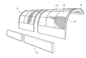
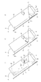
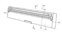
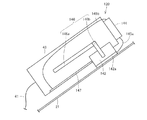
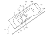
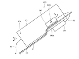
本発明の一実施形態にかかる空気調和機の室内機の外観を示す斜視図である。It is a perspective view which shows the external appearance of the indoor unit of the air conditioner concerning one Embodiment of this invention. 図1に示す室内機の内部構成を示す断面図である。It is sectional drawing which shows the internal structure of the indoor unit shown in FIG. 図1に示す室内機に備えられたフィルタ及びフィルタ清掃装置を示す斜視図である。It is a perspective view which shows the filter and filter cleaning apparatus with which the indoor unit shown in FIG. 1 was equipped. 図1に示す空気調和機に備えられたフィルタ及びフィルタ清掃装置を示す分解斜視図である。It is a disassembled perspective view which shows the filter and filter cleaning apparatus with which the air conditioner shown in FIG. 1 was equipped. 本発明の第1の実施形態にかかるフィルタ清掃装置の内部構成を示す断面模式図である。It is a cross-sectional schematic diagram which shows the internal structure of the filter cleaning apparatus concerning the 1st Embodiment of this invention. (a)から(c)は、フィルタ清掃装置内のブラシの動作を順に示す図である。(A)-(c) is a figure which shows operation | movement of the brush in a filter cleaning apparatus in order. 第1の実施形態にかかるフィルタ清掃装置の変形例の外観構成を示す斜視図である。この図では、フィルタ清掃装置のフィルタと接触する側を上面にした状態を示す。It is a perspective view which shows the external appearance structure of the modification of the filter cleaning apparatus concerning 1st Embodiment. In this figure, the state which made the side which contacts the filter of a filter cleaning apparatus the upper surface is shown. 本発明の第2の実施形態にかかるフィルタ清掃装置の内部構成を示す断面模式図である。It is a cross-sectional schematic diagram which shows the internal structure of the filter cleaning apparatus concerning the 2nd Embodiment of this invention. 図8に示すフィルタ清掃装置内のブラシの動作を示す図である。It is a figure which shows operation | movement of the brush in the filter cleaning apparatus shown in FIG. 本発明の第3の実施形態にかかるフィルタ清掃装置の内部構成を示す断面図である。It is sectional drawing which shows the internal structure of the filter cleaning apparatus concerning the 3rd Embodiment of this invention. 本発明の第4の実施形態にかかるフィルタ清掃装置の内部構成を示す断面図である。It is sectional drawing which shows the internal structure of the filter cleaning apparatus concerning the 4th Embodiment of this invention. 本発明の第5の実施形態にかかるフィルタ清掃装置の内部構成を示す断面図である。It is sectional drawing which shows the internal structure of the filter cleaning apparatus concerning the 5th Embodiment of this invention.

以下、図面を参照しつつ、本発明の実施の形態について説明する。以下の説明では、同一の部品には同一の符号を付してある。それらの名称および機能も同じである。したがって、それらについての詳細な説明は繰り返さない。
〔第1の実施形態〕
Hereinafter, embodiments of the present invention will be described with reference to the drawings. In the following description, the same parts are denoted by the same reference numerals. Their names and functions are also the same. Therefore, detailed description thereof will not be repeated.
[First Embodiment]

第1の実施形態では、本発明にかかるフィルタ清掃装置を内蔵している空気調和機を例に挙げて説明する。図1は、本実施の形態に係る空気調和機の室内機1の外観構成を示す。図2は、室内機1の内部構成を示す。   In the first embodiment, an air conditioner incorporating a filter cleaning device according to the present invention will be described as an example. FIG. 1 shows an external configuration of an indoor unit 1 of an air conditioner according to the present embodiment. FIG. 2 shows an internal configuration of the indoor unit 1.

<空気調和機の全体構成>
先ず、本実施の形態にかかる空気調和機の全体構成について説明する。本実施の形態にかかる空気調和機は、セパレート式の空気調和機であって、主として、室内機1と室外機(図示せず)とから構成されている。
<Overall configuration of air conditioner>
First, the whole structure of the air conditioner concerning this Embodiment is demonstrated. The air conditioner according to the present embodiment is a separate type air conditioner, and mainly includes an indoor unit 1 and an outdoor unit (not shown).

室外機には、圧縮機、室外側熱交換器、四方弁、室外ファンなどが備えられている。これらと室内機1側に備えられた室内側熱交換器31とによって冷凍サイクルが形成される。   The outdoor unit includes a compressor, an outdoor heat exchanger, a four-way valve, an outdoor fan, and the like. These and the indoor side heat exchanger 31 provided on the indoor unit 1 side form a refrigeration cycle.

次に、室内機1の構成について、図1及び図2を用いて説明する。図1に示すように、室内機1は、略直方体状の形状を有しており、通常、部屋の壁の上部に掛けられて使用される。上述したように、室内機1内には室内側熱交換器31が備えられている。この室内側熱交換器31は、冷媒配管(図示せず)を介して室外機側の圧縮機などと接続されている。これにより、この室内機1と室外機とは、冷凍サイクルを構成し、その結果、空気調和機として機能する。なお、冷凍サイクルを制御する制御部は、室内機1内の電装品ユニットに設けられる。   Next, the configuration of the indoor unit 1 will be described with reference to FIGS. 1 and 2. As shown in FIG. 1, the indoor unit 1 has a substantially rectangular parallelepiped shape, and is usually used by being hung on the upper part of the wall of the room. As described above, the indoor unit 1 is provided with the indoor heat exchanger 31. The indoor heat exchanger 31 is connected to a compressor on the outdoor unit side through a refrigerant pipe (not shown). Thereby, this indoor unit 1 and the outdoor unit constitute a refrigeration cycle, and as a result, function as an air conditioner. A control unit that controls the refrigeration cycle is provided in the electrical component unit in the indoor unit 1.

図2に示すように、室内機1は、主として、筐体10、フィルタ清掃装置20、フィルタ21、空気調和ユニット30、および電装品ユニット(図示せず)を備えている。以下、これらの各構成部材についてそれぞれ詳述する。   As shown in FIG. 2, the indoor unit 1 mainly includes a housing 10, a filter cleaning device 20, a filter 21, an air conditioning unit 30, and an electrical component unit (not shown). Hereinafter, each of these structural members will be described in detail.

筐体10は、略直方体状の樹脂成形品である。図1に示すように、筐体10は、主として、前面パネル11、本体パネル12、および背面パネル13で構成されている。筐体10の内部には、フィルタ清掃装置20、フィルタ21、空気調和ユニット30、および電装品ユニットなどが収容されている。   The housing 10 is a resin product having a substantially rectangular parallelepiped shape. As shown in FIG. 1, the housing 10 mainly includes a front panel 11, a main body panel 12, and a back panel 13. A filter cleaning device 20, a filter 21, an air conditioning unit 30, an electrical component unit, and the like are accommodated in the housing 10.

また、筐体10の上面には、吸込み口14が設けられている。この吸込み口14から、室内機1が設置されている室内の空気が室内機1内に取り込まれる。そして、図2に示すように、この吸込み口14の真下には、フィルタ21が配置されている。   A suction port 14 is provided on the upper surface of the housing 10. The indoor air in which the indoor unit 1 is installed is taken into the indoor unit 1 from the suction port 14. As shown in FIG. 2, a filter 21 is disposed directly below the suction port 14.

また、本体パネル12の下部には、フラップ15が連結されている。フラップ15は、運転停止時、筐体10の底板を構成する。なお、フラップ15には、駆動モータ(図示せず)が連結されている。駆動モータは、信号線を介して電装品ユニットに通信接続されており、空気調和機の運転中、電装品ユニット内の制御部からの制御信号に従ってフラップ15の回動角度を調節する。   A flap 15 is connected to the lower part of the main body panel 12. The flap 15 constitutes a bottom plate of the housing 10 when the operation is stopped. A drive motor (not shown) is connected to the flap 15. The drive motor is communicatively connected to the electrical component unit via a signal line, and adjusts the rotation angle of the flap 15 according to a control signal from the control unit in the electrical component unit during operation of the air conditioner.

例えば、冷房運転時には、電装品ユニット内の制御部は、フラップ15が冷風を斜め上方向に導き、冷風が天井に沿って吹き出すように、フラップ15の回動角度を調節する。暖房運転時には、電装品ユニット内の制御部は、フラップ15が前方に向かって吹き出される温風を押さえ込み、温風を床面方向に導くように、フラップ15の回動角度を調節する。なお、冷房運転の初期時には、冷風が床面方向に吹き出されるようにフラップ15の回動角度を調節し、急速冷房を行ってもよい。また、フラップ15は、運転停止時には閉状態となって、筐体10の底板を構成する。   For example, during the cooling operation, the control unit in the electrical component unit adjusts the rotation angle of the flap 15 so that the flap 15 guides the cold air obliquely upward and the cold air blows out along the ceiling. During the heating operation, the control unit in the electrical component unit adjusts the rotation angle of the flap 15 so as to suppress the warm air blown forward by the flap 15 and guide the warm air toward the floor surface. In addition, at the initial stage of the cooling operation, rapid cooling may be performed by adjusting the rotation angle of the flap 15 so that the cold air is blown out toward the floor surface. Further, the flap 15 is closed when the operation is stopped, and constitutes a bottom plate of the housing 10.

空気調和ユニット30は、図2に示すように、主として、室内側熱交換器31、およびクロスフローファン32を備えている。   As shown in FIG. 2, the air conditioning unit 30 mainly includes an indoor heat exchanger 31 and a cross flow fan 32.

室内側熱交換器31は、複数の熱交換器を、クロスフローファン32を覆う屋根(逆V字形状やλ形状と呼ばれることもある)のように組み合わせたものである。なお、各熱交換器は、左右両端で複数回折り返された伝熱管(図示せず)に多数の放熱フィン(図示せず)が取り付けられたものであって、冷房運転時には蒸発器として機能し、暖房運転時には凝縮器として機能する。   The indoor heat exchanger 31 is a combination of a plurality of heat exchangers such as a roof (also called an inverted V shape or a λ shape) that covers the cross flow fan 32. Each heat exchanger has a large number of radiating fins (not shown) attached to a heat transfer tube (not shown) bent back and forth at both left and right ends, and functions as an evaporator during cooling operation. It functions as a condenser during heating operation.

クロスフローファン32は、駆動モータ(図示せず)に連結されている。そして、クロスフローファン32は、空気調和機の運転中、その駆動モータによって回転駆動され、室内の空気を筐体10に吸い込んで室内側熱交換器31に供給すると共に、室内側熱交換器31で熱交換された空気を室内に送出する。なお、駆動モータは、信号線を介して電装品ユニットに通信接続されており、電装品ユニット内の制御部から送信される制御信号に従って動作する。   The cross flow fan 32 is connected to a drive motor (not shown). The cross flow fan 32 is rotationally driven by the drive motor during the operation of the air conditioner, sucks indoor air into the housing 10 and supplies the indoor air to the indoor heat exchanger 31, and also the indoor heat exchanger 31. The air that has been heat-exchanged in is sent out indoors. The drive motor is communicatively connected to the electrical component unit via a signal line, and operates according to a control signal transmitted from a control unit in the electrical component unit.

電装品ユニットは、例えば、筐体10内の右側端部に配置される。電装品ユニットは、中央処理演算部(制御部)、信号送受信部などで構成されている。電装品ユニットは、信号線を介して、冷凍サイクルの各構成部材と接続されている。そして、電装ユニット内の制御部は、ユーザの指示、および室温や外気温を検出する温度センサ等の各種のセンサの検出信号に基づいて、冷凍サイクルを制御し、冷房運転および暖房運転を行う。   The electrical component unit is disposed, for example, at the right end in the housing 10. The electrical component unit includes a central processing calculation unit (control unit), a signal transmission / reception unit, and the like. The electrical component unit is connected to each component of the refrigeration cycle via a signal line. And the control part in an electrical equipment unit controls a refrigerating cycle based on a user's instruction | indication and the detection signal of various sensors, such as a temperature sensor which detects room temperature and external temperature, and performs air_conditionaing | cooling operation and heating operation.

また、電装品ユニットは、信号線を介して、クロスフローファン32の駆動モータ、フラップ15の駆動モータ、フィルタ清掃装置20の駆動モータ、フィルタ清掃装置20内の各部材の電源部などとも接続されている。   The electrical component unit is also connected to the drive motor of the cross flow fan 32, the drive motor of the flap 15, the drive motor of the filter cleaning device 20, the power supply unit of each member in the filter cleaning device 20 and the like via signal lines. ing.

フィルタ21は、吸込み口14と室内側熱交換器31との間に設けられている。説明の便宜上、吸込み口14と対向しているフィルタ21の面を表面とし、室内側熱交換器31と対向しているフィルタ21の面をフィルタの裏面とする。図2に示すように、フィルタ21は、筐体10に設けられた吸込み口14の形状に沿うように配置されている。フィルタ21は、吸込み口14から室内機1の内部に取り込まれる空気に含まれる埃や塵を捕捉する。これにより、室内機1の内部に取り込まれる空気中の埃や塵の量を減らすことができる。   The filter 21 is provided between the suction port 14 and the indoor heat exchanger 31. For convenience of explanation, the surface of the filter 21 facing the suction port 14 is defined as the front surface, and the surface of the filter 21 facing the indoor heat exchanger 31 is defined as the back surface of the filter. As shown in FIG. 2, the filter 21 is disposed along the shape of the suction port 14 provided in the housing 10. The filter 21 captures dust and dirt contained in the air taken into the indoor unit 1 from the suction port 14. Thereby, the amount of dust and dust in the air taken into the indoor unit 1 can be reduced.

本実施形態にかかる室内機1には、2つのフィルタ21が、左右に並んで配置されている(図3参照)。しかし、本発明の空気調和機におけるフィルタの個数及び配置は、これに限定はされない。例えば、吸込み口14の全領域をカバーするような1枚のフィルタで構成してもよい。   In the indoor unit 1 according to the present embodiment, two filters 21 are arranged side by side (see FIG. 3). However, the number and arrangement of the filters in the air conditioner of the present invention are not limited to this. For example, you may comprise with one filter which covers the whole area | region of the suction inlet 14. FIG.

フィルタ清掃装置20は、フィルタ21の表面上に配置されている。フィルタ清掃装置20は、各フィルタ21に対してそれぞれ設けられている。すなわち、本実施形態の室内機1には、右側のフィルタ21と左側のフィルタ21のそれぞれに対して、フィルタ清掃装置20が1個ずつ設けられており、合計で2個のフィルタ清掃装置20が備えられている。また、本実施形態では、フィルタ清掃装置20は、フィルタ21の左右方向(水平方向)に沿って、フィルタ21の一端部から他端部に延びるように配置されている(図3参照)。   The filter cleaning device 20 is disposed on the surface of the filter 21. The filter cleaning device 20 is provided for each filter 21. That is, in the indoor unit 1 of the present embodiment, one filter cleaning device 20 is provided for each of the right filter 21 and the left filter 21, and two filter cleaning devices 20 in total are provided. Is provided. Moreover, in this embodiment, the filter cleaning apparatus 20 is arrange | positioned so that the other end part may be extended from the one end part of the filter 21 along the left-right direction (horizontal direction) of the filter 21 (refer FIG. 3).

フィルタ清掃装置20には、駆動モータ(駆動部)40が備えられている。駆動モータ40は、リード線41によってフィルタ清掃装置20の本体(具体的には、ダストボックス43)と接続されている。フィルタ清掃装置20は、この駆動モータ40によって駆動され、フィルタ21の表面上を前後方向に移動することができる。ここで、前後方向とは、室内機1を通常の状態で設置した場合に、室内機1の正面側から背面側へ向かう方向または背面側から正面側へ向かう方向を意味する。また、前後方向の移動には、本実施形態のように、移動の軌跡がフィルタの形状に沿って曲線を描くように、上下且つ前後に移動することも含む。後述するように、フィルタ清掃装置20のフィルタ21との対向面には、ブラシ(埃取り部材)42が設けられている。そのため、フィルタ清掃装置20が、フィルタ21の表面上を移動することで、フィルタ21の表面に付着した埃などをブラシ42よって捕捉することができる。   The filter cleaning device 20 includes a drive motor (drive unit) 40. The drive motor 40 is connected to the main body (specifically, the dust box 43) of the filter cleaning device 20 by a lead wire 41. The filter cleaning device 20 is driven by the drive motor 40 and can move on the surface of the filter 21 in the front-rear direction. Here, the front-rear direction means a direction from the front side to the back side of the indoor unit 1 or a direction from the back side to the front side when the indoor unit 1 is installed in a normal state. In addition, the movement in the front-rear direction includes moving up and down and back and forth so that the locus of movement draws a curve along the shape of the filter as in this embodiment. As will be described later, a brush (dust removing member) 42 is provided on the surface of the filter cleaning device 20 facing the filter 21. Therefore, when the filter cleaning device 20 moves on the surface of the filter 21, dust attached to the surface of the filter 21 can be captured by the brush 42.

駆動モータ40は、信号線を介して電装品ユニットに通信接続されている。そして、電装品ユニット内の制御部は、必要に応じて駆動モータ40に対して制御信号を送り、フィルタ清掃装置20を駆動させる。これにより、フィルタ清掃装置20によるフィルタ21表面の清掃が行われる。フィルタ清掃装置20を稼働させるタイミングは適宜決めることができる。例えば、空気調和機の運転を停止させた後に、フィルタ清掃装置20を稼働させてもよい。   The drive motor 40 is communicatively connected to the electrical component unit via a signal line. And the control part in an electrical component unit sends a control signal with respect to the drive motor 40 as needed, and drives the filter cleaning apparatus 20. FIG. As a result, the surface of the filter 21 is cleaned by the filter cleaning device 20. The timing for operating the filter cleaning device 20 can be determined as appropriate. For example, the filter cleaning device 20 may be operated after stopping the operation of the air conditioner.

また、本実施形態では、フィルタ清掃装置20は、フィルタ21の表面上を前後方向に移動させる構成としているが、本発明では、フィルタ清掃装置の移動方向は前後方向に限定されない。例えば、フィルタ清掃装置の移動方向は、左右方向(水平方向)であってもよい。フィルタ清掃装置が左右方向に移動する場合には、フィルタ清掃装置20は、フィルタ21に対して縦方向(前後方向)に延びるように配置するのがよい。   Moreover, in this embodiment, although the filter cleaning apparatus 20 is set as the structure which moves on the surface of the filter 21 in the front-back direction, in this invention, the moving direction of a filter cleaning apparatus is not limited to the front-back direction. For example, the moving direction of the filter cleaning device may be the left-right direction (horizontal direction). When the filter cleaning device moves in the left-right direction, the filter cleaning device 20 is preferably arranged so as to extend in the vertical direction (front-rear direction) with respect to the filter 21.

<フィルタ及びフィルタ清掃装置の構成>
続いて、室内機1に備えられたフィルタ21及びフィルタ清掃装置20のより具体的な構成について、図2から図6を参照しながら説明する。
<Configuration of filter and filter cleaning device>
Next, more specific configurations of the filter 21 and the filter cleaning device 20 provided in the indoor unit 1 will be described with reference to FIGS. 2 to 6.

図3及び図4には、室内機1内に備えられたフィルタ21及びフィルタ清掃装置20の外観構成を示す。図3は、フィルタ21に対してフィルタ清掃装置20を装着させた状態を示す。図4は、フィルタ清掃装置20をフィルタ21から取り外した状態を示す。図5は、フィルタ清掃装置20の内部の構成を示す。この図は、図3に示すX−X線での断面に相当する。図6の(a)から(c)には、フィルタ清掃装置内のブラシの動作を順に示す。   3 and 4 show the external configuration of the filter 21 and the filter cleaning device 20 provided in the indoor unit 1. FIG. 3 shows a state in which the filter cleaning device 20 is attached to the filter 21. FIG. 4 shows a state where the filter cleaning device 20 is removed from the filter 21. FIG. 5 shows an internal configuration of the filter cleaning device 20. This figure corresponds to a cross section taken along line XX shown in FIG. 6A to 6C sequentially show the operation of the brush in the filter cleaning device.

フィルタ21は、メッシュ部22と、メッシュ部22の周囲を取り囲む枠体23とで構成されている。メッシュ部22は、例えば、網目状の不織布で形成され、枠体23は、例えば、ポリプロピレン樹脂などの構成樹脂で形成される。またあるいは、メッシュ部22と枠体23とは、ポリプロピレン樹脂等の合成樹脂により一体的に成形されてもよい。   The filter 21 includes a mesh portion 22 and a frame body 23 that surrounds the mesh portion 22. The mesh portion 22 is formed of, for example, a mesh-like nonwoven fabric, and the frame body 23 is formed of, for example, a constituent resin such as polypropylene resin. Alternatively, the mesh portion 22 and the frame body 23 may be integrally formed with a synthetic resin such as a polypropylene resin.

また、枠体23は、複数のリブ23aを有している。各リブ23aは、枠体23の内部を縦または横に略等間隔に延びており、これにより、メッシュ部22の表面は碁盤目状に区画される。この構成により、フィルタ21の強度が高まる。なお、リブ23aの厚さは、枠体23の枠部分の厚さよりも小さくなっている。   The frame body 23 has a plurality of ribs 23a. Each rib 23a extends in the frame body 23 vertically or horizontally at substantially equal intervals, whereby the surface of the mesh portion 22 is partitioned in a grid pattern. With this configuration, the strength of the filter 21 is increased. Note that the thickness of the rib 23 a is smaller than the thickness of the frame portion of the frame body 23.

そして、リブ23aの厚さは、メッシュ部22の厚さと略同じであることが好ましい。これにより、メッシュ部22とリブ23aとで形成されるフィルタ21の表面を、略面一とすることができる。またあるいは、リブ23aは、フィルタ21の裏面側に配置されることが好ましい。これにより、メッシュ部22の表面を、略面一とすることができる。フィルタ21の表面が略面一であることによって、フィルタ21の表面に付着した埃や塵などを、フィルタ清掃装置20によってより容易に取り除くことができる。   And it is preferable that the thickness of the rib 23a is substantially the same as the thickness of the mesh part 22. FIG. Thereby, the surface of the filter 21 formed with the mesh part 22 and the rib 23a can be made substantially flush. Alternatively, the rib 23a is preferably disposed on the back side of the filter 21. Thereby, the surface of the mesh part 22 can be made substantially flush. Since the surface of the filter 21 is substantially flush, dust or dirt attached to the surface of the filter 21 can be easily removed by the filter cleaning device 20.

また、一例では、枠体23の縦方向(上下方向)の枠部分に、複数の突起部24が形成されていてもよい。このような突起部24は、後述するように、駆動モータを用いずにブラシ42の回転動作を行う構成のフィルタ清掃装置(例えば、フィルタ清掃装置620)に設けることが好ましい。   In one example, a plurality of protrusions 24 may be formed on the frame portion in the vertical direction (vertical direction) of the frame body 23. Such a protrusion 24 is preferably provided in a filter cleaning device (for example, the filter cleaning device 620) configured to rotate the brush 42 without using a drive motor, as will be described later.

図2及び図5に示すように、フィルタ清掃装置20は、主として、駆動モータ40、リード線41、ブラシ42、ダストボックス(埃収容部)43、電源部(電圧印加部)44、リード線45、および補助ブラシ(埃移動部材)46を備えている。なお、図5では、駆動モータ40の図示は省略している。   As shown in FIGS. 2 and 5, the filter cleaning device 20 mainly includes a drive motor 40, a lead wire 41, a brush 42, a dust box (dust storage unit) 43, a power supply unit (voltage application unit) 44, a lead wire 45, An auxiliary brush (dust moving member) 46 is provided. In FIG. 5, the drive motor 40 is not shown.

駆動モータ40は、リード線41を介してダストボックス43と接続されている。駆動モータ40は、制御部からの制御信号に基づいて動作する。そして、駆動モータ40は、ダストボックス43を前後方向(矢印Aの方向または矢印Bの方向)に移動させる。   The drive motor 40 is connected to the dust box 43 via the lead wire 41. The drive motor 40 operates based on a control signal from the control unit. Then, the drive motor 40 moves the dust box 43 in the front-rear direction (the direction of arrow A or the direction of arrow B).

ブラシ42は、その表面(または先端)42aがフィルタ21の表面と接触するように配置され、フィルタ21上に付着した埃61を捕捉する。すなわち、ブラシ42の表面42aが埃を捕捉する埃捕捉部になっている。この埃捕捉部は、例えば、パイル状に起毛させた繊維(例えば、ナイロンなどの合成繊維、動物毛などの天然繊維)で形成される織布または不織布、適度な剛性を有する繊維(例えば、ナイロンなどの合成繊維、動物毛などの天然繊維)を複数本束ねて得られるブラシ、粘着性を有する素材などで形成することができる。本実施形態では、ブラシ42は、回転軸42bに対して矢印C方向に回転可能に軸支されている。   The brush 42 is arranged such that its surface (or tip) 42 a comes into contact with the surface of the filter 21, and captures the dust 61 adhering to the filter 21. That is, the surface 42a of the brush 42 is a dust trapping part that traps dust. This dust trapping part is, for example, a woven or non-woven fabric formed of fibers raised in a pile shape (for example, synthetic fibers such as nylon, natural fibers such as animal hair), or fibers having appropriate rigidity (for example, nylon) A synthetic fiber such as animal fibers, natural fibers such as animal hair), a brush obtained by bundling a plurality of fibers, and a sticky material. In the present embodiment, the brush 42 is pivotally supported so as to be rotatable in the arrow C direction with respect to the rotation shaft 42b.

なお、本発明において、埃取り部材は、上記のような織布、ブラシなどに限定されることはない。埃取り部材は、フィルタ21の表面に物理的に作用し、フィルタ表面に存在する埃を拭き取ったり、擦り取ったり、絡め取ったりすることで、埃を捕捉することのできるものであればよい。例えば、ブラシ42(埃取り部材)が、織布または不織布である場合には、「埃を捕捉する」とは、「埃を拭き取る」と言い換えることもできる。また、ブラシ42(埃取り部材)が、剛性繊維を複数本束ねたブラシの場合には、「埃を捕捉する」とは、「埃を擦り取る」と言い換えることもできる。   In the present invention, the dust removing member is not limited to the woven fabric, the brush and the like as described above. The dust removing member may be any member that can physically act on the surface of the filter 21 and can capture dust by wiping, rubbing, or entwining the dust existing on the filter surface. For example, when the brush 42 (dust removing member) is a woven fabric or a non-woven fabric, “capturing dust” can be rephrased as “wiping off dust”. Further, when the brush 42 (dust removing member) is a brush in which a plurality of rigid fibers are bundled, “capturing dust” can be rephrased as “scraping off dust”.

ブラシ42が回転可能な構成であることにより、フィルタ21表面上の埃61などを捕捉する際には、ブラシ42の表面(または先端)42aを、フィルタ21の表面と対向するように配置させることができる。また、ブラシ42に付着した埃などをダストボックス43内に移す際には、ブラシ42を矢印C方向に回転させることができる。   Since the brush 42 is configured to be rotatable, when the dust 61 on the surface of the filter 21 is captured, the surface (or tip) 42a of the brush 42 is disposed so as to face the surface of the filter 21. Can do. Further, when moving dust or the like adhering to the brush 42 into the dust box 43, the brush 42 can be rotated in the direction of arrow C.

ブラシ42の回転動作は、駆動モータ(図示せず)によって行ってもよいし、後述するような引っ掛け部材47a・47b(図7参照)の作用によってフィルタ清掃装置20の上下方向(図7中の矢印A及びB方向)の移動に連動させるようにしてもよい。駆動モータは、例えば、リード線45及び電源部44と同じような位置に取り付けることができる。   The rotation of the brush 42 may be performed by a drive motor (not shown), or the filter cleaning device 20 in the vertical direction (in FIG. 7) by the action of hook members 47a and 47b (see FIG. 7) described later. The movement in the directions of arrows A and B) may be interlocked. The drive motor can be mounted at the same position as the lead wire 45 and the power supply unit 44, for example.

ダストボックス43は、直方体状の箱型の部材である。ダストボックス43は、例えば、剛性を有する合成樹脂(プラスチック)で形成される。ダストボックス43は、ブラシ42によってフィルタ21表面から拭き取られるなどした埃、塵、ゴミなどを、その内部に集積させる。   The dust box 43 is a rectangular parallelepiped box-shaped member. The dust box 43 is formed of, for example, a synthetic resin (plastic) having rigidity. The dust box 43 accumulates dust, dust, dust, and the like that have been wiped off from the surface of the filter 21 by the brush 42 therein.

電源部44は、ダストボックス43の外側(例えば、図5に示すようにダストボックス43の上面)に取り付けられている。電源部44は、リード線45を介してブラシ42に接続されている。これにより、ブラシ42には、電源部44によって微小な電圧が印加される。そして、ブラシ42は、プラスまたはマイナスの何れかに帯電する。このようにブラシ42を帯電させることで、静電気力によって、フィルタ21表面上の埃をブラシ42側へひきつけることができる。   The power supply unit 44 is attached to the outside of the dust box 43 (for example, the upper surface of the dust box 43 as shown in FIG. 5). The power supply unit 44 is connected to the brush 42 via the lead wire 45. As a result, a minute voltage is applied to the brush 42 by the power supply unit 44. The brush 42 is charged either positively or negatively. By charging the brush 42 in this way, dust on the surface of the filter 21 can be attracted to the brush 42 side by electrostatic force.

したがって、ブラシ42がフィルタ21の表面を移動する際に、ブラシ42とフィルタ21との摩擦によってフィルタ21表面上の埃を擦り取るだけでなく、摩擦のみでは取り切れなかった埃などを、静電気力によってブラシ42側へ吸着させることができる。なお、ブラシ42は、プラスに帯電させてもよいし、マイナスに帯電させてもよい。   Therefore, when the brush 42 moves on the surface of the filter 21, not only the dust on the surface of the filter 21 is rubbed off due to friction between the brush 42 and the filter 21 but also dust or the like that cannot be removed only by the friction is removed by electrostatic force. Can be adsorbed to the brush 42 side. The brush 42 may be charged positively or negatively.

補助ブラシ46は、ダストボックス43の内部に配置されている。補助ブラシ46は、ブラシ42と同様の素材で形成することができる。なお、ブラシ42と補助ブラシ46とは、同一の素材で形成してもよいし、異なる素材で形成してもよい。補助ブラシ46は、ブラシ42がフィルら21から拭き取った埃を、ダストボックス43内へ移動させる役割を果たす。   The auxiliary brush 46 is disposed inside the dust box 43. The auxiliary brush 46 can be formed of the same material as the brush 42. Note that the brush 42 and the auxiliary brush 46 may be formed of the same material or different materials. The auxiliary brush 46 serves to move the dust wiped from the fills 21 by the brush 42 into the dust box 43.

例えば、補助ブラシ46は、ブラシ42を矢印C方向に回転させてダストボックス43内に収容したときに、お互いのブラシの表面が接触し合うような位置に配置されている。これにより、補助ブラシ46の表面とブラシ42の表面42aとの間で発生する摩擦によって、ブラシ42に付着した埃61をダストボックス43内の底面部43aの方に移動させることができる。   For example, the auxiliary brush 46 is disposed at a position where the brush surfaces come into contact with each other when the brush 42 is rotated in the direction of arrow C and accommodated in the dust box 43. Thereby, the dust 61 adhering to the brush 42 can be moved toward the bottom surface portion 43 a in the dust box 43 by friction generated between the surface of the auxiliary brush 46 and the surface 42 a of the brush 42.

続いて、フィルタ21の清掃を行う際のフィルタ清掃装置20の動作について、図6を参照しながら説明する。図6(a)から図6(c)には、フィルタ清掃装置20を用いたフィルタ21の清掃方法を、各工程順に示す。   Next, the operation of the filter cleaning device 20 when cleaning the filter 21 will be described with reference to FIG. FIG. 6A to FIG. 6C show a method of cleaning the filter 21 using the filter cleaning device 20 in the order of each process.

フィルタ21の清掃を行う場合には、先ず、フィルタ清掃装置20は、矢印A方向に移動する。このとき、ブラシ42の表面42aはフィルタ21の表面と接触しながら、フィルタ21の表面に沿って移動する(図6(a)参照)。このとき、ブラシ42の表面42aには、プラスまたはマイナスの電荷が印加されているため、静電気力によって埃61をブラシ42側へ引き付けることができる。そのため、ブラシ42が帯電していない場合と比較して、フィルタ21の表面に付着したより多くの埃61をフィルタ21表面から取り去ることができる。   When cleaning the filter 21, first, the filter cleaning device 20 moves in the arrow A direction. At this time, the surface 42a of the brush 42 moves along the surface of the filter 21 while being in contact with the surface of the filter 21 (see FIG. 6A). At this time, since a positive or negative charge is applied to the surface 42a of the brush 42, the dust 61 can be attracted to the brush 42 side by electrostatic force. Therefore, more dust 61 adhering to the surface of the filter 21 can be removed from the surface of the filter 21 than when the brush 42 is not charged.

続いて、ブラシ42に付着した埃61をダストボックス43内へ移す動作を、図6(b)および図6(c)を参照しながら説明する。ブラシ42に付着した埃61をダストボックス43内へ移す際には、フィルタ清掃装置20の移動は停止される。そして、図6(b)に示すように、駆動モータ(図示せず)によって、ブラシ42を矢印C方向に回転させる。これにより、ブラシ42は、ダストボックス43内に収容される。   Subsequently, an operation of moving the dust 61 adhering to the brush 42 into the dust box 43 will be described with reference to FIGS. 6B and 6C. When the dust 61 adhering to the brush 42 is moved into the dust box 43, the movement of the filter cleaning device 20 is stopped. Then, as shown in FIG. 6B, the brush 42 is rotated in the direction of arrow C by a drive motor (not shown). Thereby, the brush 42 is accommodated in the dust box 43.

そして、駆動モータは、ブラシ42をさらに上方へ回転させる。すると、図6(c)に示すように、ブラシ42の表面42aは、補助ブラシ46の表面(または先端部)と接触する。このとき、補助ブラシ46の表面とブラシ42の表面42aとの間で発生する摩擦によって、ブラシ42に付着した埃61は、ダストボックス43内の底面部43aの方に落ちる。   Then, the drive motor rotates the brush 42 further upward. Then, as shown in FIG. 6C, the surface 42 a of the brush 42 comes into contact with the surface (or tip portion) of the auxiliary brush 46. At this time, the dust 61 adhering to the brush 42 falls toward the bottom surface portion 43 a in the dust box 43 due to friction generated between the surface of the auxiliary brush 46 and the surface 42 a of the brush 42.

以上の一連の動作によって、フィルタ21の表面に付着した埃61を、ブラシ42で捕捉し、ダストボックス43内へ移すことができる。ダストボックス43内へ埃を移動させた後、ブラシ42をフィルタへ接触させ、再び清掃を開始する。これを繰り返すことでフィルタを清掃することができる。   Through the series of operations described above, the dust 61 adhering to the surface of the filter 21 can be captured by the brush 42 and moved into the dust box 43. After the dust is moved into the dust box 43, the brush 42 is brought into contact with the filter, and cleaning is started again. By repeating this, the filter can be cleaned.

なお、図6(b)及び図6(c)に示す工程は、例えば、フィルタ清掃装置20の1回の埃取り動作が終了した時点で(すなわち、フィルタ清掃装置20がフィルタ21の最上部に位置するときに)行うことができる。またあるいは、1回の埃取り動作中に、図6(b)及び図6(c)に示す工程を定期的に複数回行うこともできる。   6B and 6C, for example, at the time when the dust cleaning operation of the filter cleaning device 20 is completed once (that is, the filter cleaning device 20 is placed on the uppermost portion of the filter 21). Can be done). Alternatively, the steps shown in FIGS. 6B and 6C can be periodically performed a plurality of times during one dust removal operation.

また、図6(c)に示す工程では、電源部44はブラシ42に対する電圧の印加を停止することが好ましい。これにより、ブラシ42の表面42aの静電気力が弱まり、表面42aに付着していた埃をより容易に落とすことができる。   In the step shown in FIG. 6C, the power supply unit 44 preferably stops the application of voltage to the brush 42. Thereby, the electrostatic force of the surface 42a of the brush 42 becomes weak, and the dust adhering to the surface 42a can be dropped more easily.

上述のように駆動モータを用いてブラシ42の回転動作を行う構成によれば、フィルタ清掃装置20の矢印A方向への移動を一旦停止させるだけで、ブラシ42に付着した埃61などをダストボックス43内へ移すことができる。そのため、1回の埃取り作業において、フィルタ清掃装置20を何度も往復させることなく、ブラシ42に付着した埃を複数回ダストボックス43内に移す動作を行うことができる。   According to the configuration in which the brush 42 is rotated using the drive motor as described above, the dust 61 or the like adhering to the brush 42 is removed from the dust box 43 only by temporarily stopping the movement of the filter cleaning device 20 in the arrow A direction. Can be moved in. Therefore, in one dust removal operation, it is possible to perform an operation of moving dust attached to the brush 42 into the dust box 43 a plurality of times without reciprocating the filter cleaning device 20 many times.

上記の構成によれば、ブラシ42を帯電させることによって、ブラシの拭き取り動作(または擦り取り動作)という力学的な作用による埃の清掃に加えて、静電気力による埃の吸着作用による埃の清掃を行うことができる。これにより、より確実にフィルタ上の埃を清掃することができる。   According to the above configuration, by charging the brush 42, in addition to cleaning the dust by the mechanical action of the brush wiping operation (or scraping operation), the cleaning of the dust by the dust adsorption action by the electrostatic force is performed. It can be carried out. Thereby, dust on the filter can be more reliably cleaned.

<フィルタ清掃装置20の変形例>
図7には、変形例として、フィルタ清掃装置620に引っ掛け部材47a・47bが設けられている構成例を示す。図7は、フィルタ清掃装置620がフィルタ21の表面の埃などを除去するときの状態を示す。なお、図7では、電源部44及び駆動モータ40の図示は省略している。
<Modification of Filter Cleaning Device 20>
FIG. 7 shows a modified example in which the filter cleaning device 620 is provided with hook members 47a and 47b. FIG. 7 shows a state where the filter cleaning device 620 removes dust and the like on the surface of the filter 21. In FIG. 7, the power supply unit 44 and the drive motor 40 are not shown.

図7に示すように、埃取り動作中は、ブラシ42の表面42aは、ダストボックス43の外側に露出している。そして、ブラシ42の左右両側の端部には、引っ掛け部材47a・47bが設けられている。   As shown in FIG. 7, the surface 42 a of the brush 42 is exposed to the outside of the dust box 43 during the dust removal operation. Further, hook members 47 a and 47 b are provided at the left and right ends of the brush 42.

引っ掛け部材47a・47bは、ゴム、シリコンなどの弾性を有する素材で形成されている。そして、フィルタ清掃装置20が前後方向(図7中の矢印A及びB方向)に移動する際に、引っ掛け部材47a・47bは、フィルタ21の枠体23に形成された各突起部24と順次噛み合いながら上方または下方に移動する。   The hook members 47a and 47b are made of an elastic material such as rubber or silicon. When the filter cleaning device 20 moves in the front-rear direction (in the directions of arrows A and B in FIG. 7), the hook members 47a and 47b sequentially mesh with the protrusions 24 formed on the frame body 23 of the filter 21. While moving up or down.

例えば、ブラシ42が埃取り動作中のとき(フィルタ清掃装置620が矢印A方向に移動しているとき)には、引っ掛け部材47a・47bは、突起部24によって矢印B側へ押される。そのため、ブラシ42の表面42aは、ダストボックス43の外側に露出した状態となる。   For example, when the brush 42 is in the dust removing operation (when the filter cleaning device 620 is moving in the direction of arrow A), the hook members 47a and 47b are pushed toward the arrow B by the protrusion 24. Therefore, the surface 42 a of the brush 42 is exposed to the outside of the dust box 43.

一方、ブラシ42の表面42aに付着した埃などをダストボックス43内に移すときには、駆動モータ40は、フィルタ清掃装置620を矢印B方向に移動させる。この移動動作によって、引っ掛け部材47a・47bは、突起部24によって矢印A側へ押される。これにより、ブラシ42の表面42aは、図6(b)に示す矢印C方向に回転し、ダストボックス43内に収容される。そして、図6(c)に示すフィルタ清掃装置20と同様に、フィルタ清掃装置620においても、ブラシ42に付着した埃61を、ダストボックス43内の底面部43aの方へ落とすことができる。   On the other hand, when moving dust or the like adhering to the surface 42a of the brush 42 into the dust box 43, the drive motor 40 moves the filter cleaning device 620 in the arrow B direction. By this moving operation, the hook members 47a and 47b are pushed to the arrow A side by the protrusion 24. As a result, the surface 42 a of the brush 42 rotates in the direction of arrow C shown in FIG. 6B and is accommodated in the dust box 43. 6C, dust 61 adhering to the brush 42 can be dropped toward the bottom surface portion 43a in the dust box 43 in the filter cleaning device 620 as well.

以上のように、変形例にかかるフィルタ清掃装置620によれば、駆動モータを用いることなくブラシ42の回転動作を行うことができる。   As described above, according to the filter cleaning device 620 according to the modification, the brush 42 can be rotated without using the drive motor.

〔第2の実施形態〕
本発明の第2の実施形態について、図8および図9を参照しながら説明する。第2の実施形態では、空気調和機の室内機1内に備えられたフィルタ清掃装置の構成が、第1の実施形態とは異なっている。フィルタ清掃装置以外の室内機の構成については、第1の実施形態と同じ構成を適用できる。そこで、以下では、第2の実施形態にかかるフィルタ清掃装置120の構成を中心に説明する。
[Second Embodiment]
A second embodiment of the present invention will be described with reference to FIGS. In 2nd Embodiment, the structure of the filter cleaning apparatus provided in the indoor unit 1 of an air conditioner differs from 1st Embodiment. About the structure of indoor units other than a filter cleaning apparatus, the same structure as 1st Embodiment is applicable. Therefore, hereinafter, the configuration of the filter cleaning device 120 according to the second embodiment will be mainly described.

図8には、第2の実施形態にかかるフィルタ清掃装置120の内部の構成を示す。フィルタ清掃装置120は、図2に示す第1の実施形態のフィルタ清掃装置20と同様に、フィルタ21の表面上に配置されている。   FIG. 8 shows an internal configuration of the filter cleaning device 120 according to the second embodiment. The filter cleaning device 120 is disposed on the surface of the filter 21 in the same manner as the filter cleaning device 20 of the first embodiment shown in FIG.

フィルタ清掃装置120は、主として、駆動モータ(駆動部)40、リード線41、ブラシ(埃取り部材)142、ダストボックス(埃収容部)43、電源部(電圧印加部)144、リード線145a・145b、および電極シート(逆帯電部材)147を備えている。なお、図8では、駆動モータ40の図示は省略している。   The filter cleaning device 120 mainly includes a drive motor (drive unit) 40, a lead wire 41, a brush (dust removing member) 142, a dust box (dust storage unit) 43, a power supply unit (voltage application unit) 144, and lead wires 145a and 145b. , And an electrode sheet (reverse charging member) 147. In FIG. 8, the drive motor 40 is not shown.

駆動モータ40、リード線41、およびダストボックス43については、第1の実施形態と同様の構成を適用することができる。   About the drive motor 40, the lead wire 41, and the dust box 43, the structure similar to 1st Embodiment is applicable.

ブラシ142は、その表面(または先端)142aがフィルタ21の表面と接触するように配置され、フィルタ21上に付着した埃を捕捉する。すなわち、ブラシ142の表面142aが埃捕捉部になっている。この埃捕捉部は、第1の実施形態のブラシ42と同様の素材で形成することができる。本実施形態では、ブラシ142は、ダストボックス43内に取り付けられた支持体146によって支持されている。支持体146は、2つの移動軸146a・146bで構成されている。   The brush 142 is arranged such that its surface (or tip) 142a is in contact with the surface of the filter 21, and captures dust adhering to the filter 21. That is, the surface 142a of the brush 142 is a dust trapping portion. This dust trapping part can be formed of the same material as the brush 42 of the first embodiment. In the present embodiment, the brush 142 is supported by a support body 146 attached in the dust box 43. The support 146 includes two moving shafts 146a and 146b.

ブラシ142が2つの移動軸146a・146bで支持されていることによって、ブラシ142は、フィルタ21の表面とダストボックス43の内部との間を移動することができる。ブラシ142の移動は、例えば、駆動モータ(図示せず)によって行うことができる。駆動モータは、例えば、電源部144と同じような位置に取り付けることができる。   Since the brush 142 is supported by the two moving shafts 146 a and 146 b, the brush 142 can move between the surface of the filter 21 and the inside of the dust box 43. The movement of the brush 142 can be performed by, for example, a drive motor (not shown). The drive motor can be mounted at the same position as the power supply unit 144, for example.

電極シート147は、ダストボックス43内の壁面に貼り付けられている。電極シート147の配置位置は特に限定されないが、本実施形態では、電極シート147は、フィルタ21に近い側の壁面に貼り付けられている。後述するように、電極シート147には、微小な電圧が印加される。これにより、ブラシ142に付着している埃を、静電気力によって電極シート147の表面に吸着させることができる。   The electrode sheet 147 is attached to the wall surface in the dust box 43. Although the arrangement position of the electrode sheet 147 is not particularly limited, in the present embodiment, the electrode sheet 147 is affixed to the wall surface near the filter 21. As will be described later, a minute voltage is applied to the electrode sheet 147. Thereby, the dust adhering to the brush 142 can be adsorbed on the surface of the electrode sheet 147 by electrostatic force.

電源部144は、ダストボックス43の外側に取り付けられている。電源部144は、リード線145aを介してブラシ42に接続されているとともに、リード線145bを介して電極シート147に接続されている。これにより、ブラシ142及び電極シート147には、電源部144によって微小な電圧が印加される。ブラシ142を帯電させることで、静電気力によって、フィルタ21表面上の埃をブラシ142側へひきつけることができる。   The power supply unit 144 is attached to the outside of the dust box 43. The power supply unit 144 is connected to the brush 42 via a lead wire 145a and is connected to the electrode sheet 147 via a lead wire 145b. As a result, a minute voltage is applied to the brush 142 and the electrode sheet 147 by the power supply unit 144. By charging the brush 142, dust on the surface of the filter 21 can be attracted to the brush 142 side by electrostatic force.

続いて、本実施形態のフィルタ清掃装置120において、ブラシ142に付着した埃をダストボックス43内へ移す方法について、図9を参照しながら説明する。   Next, a method for transferring dust adhering to the brush 142 into the dust box 43 in the filter cleaning device 120 of the present embodiment will be described with reference to FIG.

ブラシ142に付着した埃をダストボックス43内へ移す際には、フィルタ清掃装置120の移動は停止される。そして、先ず、駆動モータは、移動軸146aを矢印D1方向に動かす。次に、駆動モータは、移動軸146bを矢印D2方向に動かす。その後、駆動モータは、移動軸146aを矢印D3方向に動かす。これにより、ブラシ142は、ダストボックス43内に収容される。   When the dust adhering to the brush 142 is moved into the dust box 43, the movement of the filter cleaning device 120 is stopped. First, the drive motor moves the moving shaft 146a in the direction of the arrow D1. Next, the drive motor moves the moving shaft 146b in the direction of arrow D2. Thereafter, the drive motor moves the moving shaft 146a in the direction of arrow D3. Thereby, the brush 142 is accommodated in the dust box 43.

これにより、ブラシ142の表面142aと電極シート147とは、接触するか近接する。この状態で、電源部144は、ブラシ142への電圧印加を停止し、その後、電極シート147への電圧印加を開始する。   As a result, the surface 142a of the brush 142 and the electrode sheet 147 are in contact with each other or close to each other. In this state, the power supply unit 144 stops voltage application to the brush 142, and then starts voltage application to the electrode sheet 147.

ブラシ142および電極シート147に印加される電圧は、プラスおよびマイナスの何れであってもよい。但し、ブラシ142に印加する電圧と、電極シート147に印加する電圧とは、逆位相とすることが好ましい。これにより、ブラシ142に付加される電荷と、電極シート147に付加される電荷との間で、正負を逆にすることができる。例えば、ブラシ142をプラスに帯電させた場合には、電極シート147をマイナスに帯電させる。これにより、ブラシ142の表面142aと電極シート147とが近づいたときに、ブラシ142の表面142a側の埃を、容易に電極シート147へ吸着させることができる。吸着後、ブラシ142を逆方向に動作させて、フィルタへ接触させ、再び清掃を開始する。これを繰り返すことでフィルタを清掃することができる。   The voltage applied to the brush 142 and the electrode sheet 147 may be positive or negative. However, it is preferable that the voltage applied to the brush 142 and the voltage applied to the electrode sheet 147 have opposite phases. Thereby, the sign can be reversed between the charge added to the brush 142 and the charge added to the electrode sheet 147. For example, when the brush 142 is charged positively, the electrode sheet 147 is charged negatively. Thereby, when the surface 142a of the brush 142 approaches the electrode sheet 147, the dust on the surface 142a side of the brush 142 can be easily adsorbed to the electrode sheet 147. After the suction, the brush 142 is moved in the reverse direction to contact the filter, and cleaning is started again. By repeating this, the filter can be cleaned.

以上のように、本実施形態にかかるフィルタ清掃装置120においては、電極シート147が、ブラシ142に付着した埃をダストボックス43内に移動させる埃移動部材としての役割を果たす。電極シート147は、ブラシ142とは逆の電荷に帯電されている。このような電極シート147を用いることにより、ブラシ142がフィルタ21から取り去った埃などを、より容易にダストボックス43内に移すことができる。   As described above, in the filter cleaning device 120 according to the present embodiment, the electrode sheet 147 serves as a dust moving member that moves the dust attached to the brush 142 into the dust box 43. The electrode sheet 147 is charged with a charge opposite to that of the brush 142. By using such an electrode sheet 147, dust or the like removed by the brush 142 from the filter 21 can be transferred into the dust box 43 more easily.

〔第3の実施形態〕
本発明の第3の実施形態について、図10を参照しながら説明する。第3の実施形態では、フィルタ清掃装置の内部の構成のみが、第2の実施形態とは異なっている。その他の構成については、第2の実施形態と同じ構成を適用できる。そこで、本実施形態にかかるフィルタ清掃装置220では、第2の実施形態のフィルタ清掃装置120とは異なる点のみについて説明する。
[Third Embodiment]
A third embodiment of the present invention will be described with reference to FIG. In 3rd Embodiment, only the structure inside a filter cleaning apparatus differs from 2nd Embodiment. About the other structure, the same structure as 2nd Embodiment is applicable. Therefore, in the filter cleaning device 220 according to the present embodiment, only differences from the filter cleaning device 120 of the second embodiment will be described.

図10には、第3の実施形態にかかるフィルタ清掃装置220の内部の構成を示す。フィルタ清掃装置220は、図2に示す第1の実施形態のフィルタ清掃装置20と同様に、フィルタ21の表面上に配置されている。   In FIG. 10, the internal structure of the filter cleaning apparatus 220 concerning 3rd Embodiment is shown. The filter cleaning device 220 is disposed on the surface of the filter 21 in the same manner as the filter cleaning device 20 of the first embodiment shown in FIG.

フィルタ清掃装置220は、主として、駆動モータ(駆動部)40、リード線41、ブラシ(埃取り部材)142、ダストボックス(埃収容部)43、電源部(電圧印加部)144、リード線145a・145b、電極シート(逆帯電部材)147、およびアース板(アース部材)249を備えている。なお、図10では、駆動モータ40の図示は省略している。   The filter cleaning device 220 mainly includes a drive motor (drive unit) 40, a lead wire 41, a brush (dust removing member) 142, a dust box (dust storage unit) 43, a power supply unit (voltage application unit) 144, and lead wires 145a and 145b. , An electrode sheet (reverse charging member) 147, and a ground plate (ground member) 249. In FIG. 10, the drive motor 40 is not shown.

駆動モータ40、リード線41、ブラシ142、ダストボックス43、電源部144、リード線145a・145b、および電極シート147については、第2の実施形態と同様の構成を適用することができる。   For the drive motor 40, the lead wire 41, the brush 142, the dust box 43, the power supply unit 144, the lead wires 145a and 145b, and the electrode sheet 147, the same configuration as that of the second embodiment can be applied.

アース板249は、接地されている。これにより、アース板249は、ゼロ電位(接地電位)となっている。アース板249は、ダストボックス43内に配置されている。より具体的には、アース板249は、ブラシ142がダストボックス43内に収容される際に、ブラシ142の表面142aと接触するような位置に配置されている。   The ground plate 249 is grounded. As a result, the ground plate 249 is at zero potential (ground potential). The ground plate 249 is disposed in the dust box 43. More specifically, the ground plate 249 is disposed at a position where it comes into contact with the surface 142 a of the brush 142 when the brush 142 is accommodated in the dust box 43.

これにより、例えば、移動軸146a・146bが図9に示すような動作を行って電極シート147に近づく前に、ブラシ142の電位をゼロ電位にすることができる。なお、ブラシ142がアース板249と接触するときには、電源部144はブラシ142に対する電圧印加を停止させていることが好ましい。例えば、電源部144は、図9に示す矢印D2の移動と、矢印D3の移動との間に、ブラシ142への電圧印加を停止させることが好ましい。これにより、ブラシ142の帯電を停止した後に、ブラシ142をアース板249に接触させることができる。   Thereby, for example, before the moving shafts 146a and 146b perform the operation as shown in FIG. 9 and approach the electrode sheet 147, the potential of the brush 142 can be made zero. Note that when the brush 142 is in contact with the ground plate 249, the power supply unit 144 preferably stops the voltage application to the brush 142. For example, the power supply unit 144 preferably stops voltage application to the brush 142 between the movement of the arrow D2 and the movement of the arrow D3 shown in FIG. Thereby, the brush 142 can be brought into contact with the ground plate 249 after charging of the brush 142 is stopped.

その後、ゼロ電位になったブラシ142は、電極シート147と接触するか近接する。この状態で、電源部144は、電極シート147への電圧印加を開始する。これにより、ブラシ142の表面142a側の埃を、容易に電極シート147へ吸着させることができる。   Thereafter, the brush 142 having zero potential comes into contact with or comes close to the electrode sheet 147. In this state, the power supply unit 144 starts voltage application to the electrode sheet 147. Thereby, the dust on the surface 142a side of the brush 142 can be easily adsorbed to the electrode sheet 147.

なお、ブラシ142の表面142aが電極シート147に近づく前に、アース板249によってブラシ142をゼロ電位とすることで、ブラシ142に印加された電圧による誘電分極の影響を弱めることができる。そのため、ブラシ142の表面142a側の埃を、より効率よく電極シート147へ吸着させることができる。   In addition, before the surface 142a of the brush 142 approaches the electrode sheet 147, the influence of the dielectric polarization by the voltage applied to the brush 142 can be weakened by setting the brush 142 to the zero potential by the ground plate 249. Therefore, the dust on the surface 142a side of the brush 142 can be adsorbed to the electrode sheet 147 more efficiently.

〔第4の実施形態〕
本発明の第4の実施形態について、図11を参照しながら説明する。第4の実施形態では、空気調和機の室内機1内に備えられたフィルタ清掃装置の構成が、第1の実施形態とは異なっている。フィルタ清掃装置以外の室内機の構成については、第1の実施形態と同じ構成を適用できる。そこで、以下では、第4の実施形態にかかるフィルタ清掃装置320の構成を中心に説明する。
[Fourth Embodiment]
A fourth embodiment of the present invention will be described with reference to FIG. In 4th Embodiment, the structure of the filter cleaning apparatus provided in the indoor unit 1 of an air conditioner differs from 1st Embodiment. About the structure of indoor units other than a filter cleaning apparatus, the same structure as 1st Embodiment is applicable. Therefore, hereinafter, the configuration of the filter cleaning device 320 according to the fourth embodiment will be mainly described.

図11には、第4の実施形態にかかるフィルタ清掃装置320の内部の構成を示す。フィルタ清掃装置320は、図2に示す第1の実施形態のフィルタ清掃装置20と同様に、フィルタ21の表面上に配置されている。   In FIG. 11, the internal structure of the filter cleaning apparatus 320 concerning 4th Embodiment is shown. The filter cleaning device 320 is disposed on the surface of the filter 21 in the same manner as the filter cleaning device 20 of the first embodiment shown in FIG.

フィルタ清掃装置320は、主として、駆動モータ40、リード線41、ブラシ(埃取り部材)342、ダストボックス(埃収容部)43、電源部(電圧印加部)344、およびリード線45を備えている。なお、図11では、駆動モータ40の図示は省略している。   The filter cleaning device 320 mainly includes a drive motor 40, a lead wire 41, a brush (dust removal member) 342, a dust box (dust storage unit) 43, a power supply unit (voltage application unit) 344, and a lead wire 45. In addition, illustration of the drive motor 40 is abbreviate | omitted in FIG.

駆動モータ40、リード線41、およびダストボックス43については、第1の実施形態と同様の構成を適用することができる。   About the drive motor 40, the lead wire 41, and the dust box 43, the structure similar to 1st Embodiment is applicable.

ブラシ342は、その表面(または先端)342aがフィルタ21の表面と接触するように配置され、フィルタ21上に付着した埃を捕捉する。すなわち、ブラシ342の表面342aが埃捕捉部になっている。この埃捕捉部は、第1の実施形態のブラシ42と同様の素材で形成することができる。   The brush 342 is disposed such that its surface (or tip) 342a is in contact with the surface of the filter 21 and captures dust adhering to the filter 21. That is, the surface 342a of the brush 342 serves as a dust trap. This dust trapping part can be formed of the same material as the brush 42 of the first embodiment.

電源部344は、ダストボックス43の外側に取り付けられている。本実施形態では、電源部344は、例えば図11に示すようにダストボックス43におけるフィルタ21との対向面に配置されている。   The power supply unit 344 is attached to the outside of the dust box 43. In this embodiment, the power supply part 344 is arrange | positioned in the opposing surface with the filter 21 in the dust box 43, as shown, for example in FIG.

本実施形態では、ブラシ342は、ダストボックス43内に取り付けられた支持軸342bによって支持されている。すなわち、ブラシ342の全体がダストボックス43内に配置されている。そして、ブラシ342は、支持軸342b上を矢印E方向にわずかに平行移動することができる。この平行移動は、例えば、駆動モータ(図示せず)によって行うことができる。駆動モータは、例えば、電源部344と同じような位置に取り付けることができる。この平行移動によって、ブラシ342の表面432aがフィルタ21の表面に接触したり、フィルタ21からわずかに離間したりすることができる。   In the present embodiment, the brush 342 is supported by a support shaft 342 b attached in the dust box 43. That is, the entire brush 342 is disposed in the dust box 43. The brush 342 can slightly translate in the direction of arrow E on the support shaft 342b. This parallel movement can be performed by, for example, a drive motor (not shown). The drive motor can be attached at the same position as the power supply unit 344, for example. By this parallel movement, the surface 432 a of the brush 342 can contact the surface of the filter 21 or be slightly separated from the filter 21.

また、本実施形態にかかるフィルタ清掃装置320では、フィルタ清掃時に、フィルタ21におけるブラシ342の表面342aとの接触部分がダストボックス43内に収容されるような構成となっている。すなわち、フィルタ清掃中に、フィルタ21が部分的にダストボックス43に噛み込まれるような構成となっている。これにより、ダストボックス43内でフィルタ21表面上の埃61などを拭き取ることができる。   Further, the filter cleaning device 320 according to the present embodiment is configured such that a contact portion of the filter 21 with the surface 342a of the brush 342 is accommodated in the dust box 43 during filter cleaning. That is, the filter 21 is partially bitten into the dust box 43 during filter cleaning. Thereby, the dust 61 etc. on the surface of the filter 21 can be wiped off in the dust box 43.

また、フィルタ清掃装置320によってフィルタ21の清掃を行う場合には、フィルタ清掃装置320は、矢印A1方向に移動する。このとき、ブラシ342の表面342aはフィルタ21の表面と接触し、ブラシ342には電源部344によって電圧が印加されている。そのため、ブラシ342とフィルタ21との摩擦によってフィルタ21表面上の埃を擦り取るだけでなく、摩擦のみでは取り切れなかった埃などを、静電気力によってブラシ342側へ吸着させることができる。   Further, when the filter 21 is cleaned by the filter cleaning device 320, the filter cleaning device 320 moves in the arrow A1 direction. At this time, the surface 342 a of the brush 342 is in contact with the surface of the filter 21, and a voltage is applied to the brush 342 by the power supply unit 344. Therefore, not only the dust on the surface of the filter 21 is rubbed off by the friction between the brush 342 and the filter 21, but also dust that cannot be removed only by the friction can be adsorbed to the brush 342 side by electrostatic force.

そして、ブラシ342に付着した埃61をダストボックス43内へ移す際には、フィルタ清掃装置20の移動は停止される。このとき、ブラシ342は、図11に示すように、駆動モータ(図示せず)によって、矢印E方向にわずかに移動する。この状態で、電源部344は、ブラシ342への電圧印加を停止する。これにより、静電気力が弱まり、ブラシ342に付着していた埃61は、ダストボックス43内に落ちる。   When the dust 61 adhering to the brush 342 is moved into the dust box 43, the movement of the filter cleaning device 20 is stopped. At this time, as shown in FIG. 11, the brush 342 moves slightly in the direction of arrow E by a drive motor (not shown). In this state, the power supply unit 344 stops voltage application to the brush 342. As a result, the electrostatic force is weakened, and the dust 61 adhering to the brush 342 falls into the dust box 43.

以上のように、本実施の形態のフィルタ清掃装置320では、ダストボックス43内でブラシ342によるフィルタ21表面の埃取り作業が行われる。そのため、ブラシ342をダストボックス43内に収納する動作を行うことなく、より簡単な動作でブラシ342に付着した埃61などをダストボックス43内に移動させることができる。   As described above, in the filter cleaning device 320 of the present embodiment, the dust removing operation on the surface of the filter 21 by the brush 342 is performed in the dust box 43. Therefore, the dust 61 and the like attached to the brush 342 can be moved into the dust box 43 with a simpler operation without performing the operation of storing the brush 342 in the dust box 43.

〔第5の実施形態〕
本発明の第5の実施形態について、図12を参照しながら説明する。第5の実施形態では、フィルタ清掃時のフィルタ清掃装置の移動方向が、第4の実施形態とは異なっている。その他の構成については、第4の実施形態と同じ構成を適用できる。そこで、本実施形態にかかるフィルタ清掃装置420では、第4の実施形態のフィルタ清掃装置320とは異なる点のみについて説明する。
[Fifth Embodiment]
A fifth embodiment of the present invention will be described with reference to FIG. In 5th Embodiment, the moving direction of the filter cleaning apparatus at the time of filter cleaning differs from 4th Embodiment. About the other structure, the same structure as 4th Embodiment is applicable. Therefore, the filter cleaning device 420 according to the present embodiment will be described only with respect to differences from the filter cleaning device 320 according to the fourth embodiment.

フィルタ清掃装置420は、主として、駆動モータ40、リード線41、ブラシ(埃取り部材)342、ダストボックス(埃収容部)43、電源部(電圧印加部)344、およびリード線45を備えている。なお、図12では、駆動モータ40の図示は省略している。フィルタ清掃装置420の各構成部材については、第4の実施形態のフィルタ清掃装置320と同様の構成を適用することができる。   The filter cleaning device 420 mainly includes a drive motor 40, a lead wire 41, a brush (dust removal member) 342, a dust box (dust storage unit) 43, a power supply unit (voltage application unit) 344, and a lead wire 45. In FIG. 12, the drive motor 40 is not shown. About each structural member of the filter cleaning apparatus 420, the structure similar to the filter cleaning apparatus 320 of 4th Embodiment is applicable.

なお、本実施形態のフィルタ清掃装置420を用いてフィルタ21の清掃を行う場合には、フィルタ清掃装置320は、矢印A2方向に移動する。このとき、ブラシ342の表面342aはフィルタ21の表面と接触し、ブラシ342には電源部344によって電圧が印加されている。そのため、ブラシ342とフィルタ21との摩擦によってフィルタ21表面上の埃を擦り取るだけでなく、摩擦のみでは取り切れなかった埃などを、静電気力によってブラシ342側へ吸着させることができる。   In addition, when cleaning the filter 21 using the filter cleaning apparatus 420 of this embodiment, the filter cleaning apparatus 320 moves in the arrow A2 direction. At this time, the surface 342 a of the brush 342 is in contact with the surface of the filter 21, and a voltage is applied to the brush 342 by the power supply unit 344. Therefore, not only the dust on the surface of the filter 21 is rubbed off by the friction between the brush 342 and the filter 21, but also dust that cannot be removed only by the friction can be adsorbed to the brush 342 side by electrostatic force.

ブラシ342によって捕捉した埃61をダストボックス43に移動させる動作については、第4の実施形態と同様にして行うことができる。   The operation of moving the dust 61 captured by the brush 342 to the dust box 43 can be performed in the same manner as in the fourth embodiment.

以上のように、本発明のフィルタ清掃装置は、フィルタ清掃時に、フィルタ21の上方から下方に向かって移動するような構成とすることもできる。フィルタ清掃装置を下方向に移動させることで、装置の移動動作に合せてダストボックスの下方(すなわち、ダストボックスの底面部43a)へ捕捉した埃を誘導することができる。   As described above, the filter cleaning device of the present invention can be configured to move downward from above the filter 21 during filter cleaning. By moving the filter cleaning device downward, it is possible to guide the dust trapped below the dust box (that is, the bottom portion 43a of the dust box) in accordance with the moving operation of the device.

〔第6の実施形態〕
上述した第1から第5の実施形態では、空気調和機に備えられているフィルタ清掃装置を例に挙げて説明した。しかし、本発明のフィルタ清掃装置は、空気清浄機、加湿機などに内蔵させることも可能である。そこで、第6の実施形態として、空調機能付き空気清浄機が本発明のフィルタ清掃装置を備えている例を挙げて説明する。図1には、第6の実施形態に係る空気清浄機の室内機501の外観構成を示す。室内機501は、室内機1とほぼ同様の構成を有している。但し、室内機501の内部には、空気清浄装置がさらに備えられている。空気清浄装置としては、例えば、イオン発生器、高性能フィルタなどを挙げることができる。空気清浄装置は、従来公知の構成を適用できる。
[Sixth Embodiment]
In the first to fifth embodiments described above, the filter cleaning device provided in the air conditioner has been described as an example. However, the filter cleaning device of the present invention can be incorporated in an air cleaner, a humidifier, or the like. Therefore, as a sixth embodiment, an example in which an air cleaner with an air conditioning function includes the filter cleaning device of the present invention will be described. In FIG. 1, the external appearance structure of the indoor unit 501 of the air cleaner which concerns on 6th Embodiment is shown. The indoor unit 501 has substantially the same configuration as the indoor unit 1. However, an air cleaning device is further provided inside the indoor unit 501. Examples of the air cleaning device include an ion generator and a high performance filter. A conventionally well-known structure can be applied to the air cleaning device.

フィルタ清掃装置の構成は、第1から第5の実施形態の何れかの構成を適用することができる。その他の構成については、室内機1と同様の構成を適用することができる。本実施形態にかかる空気清浄機は、本発明のフィルタ清掃装置を内蔵しているため、従来の空気清浄機と比較して、フィルタに付着した埃をより確実に清掃することができる。   As the configuration of the filter cleaning device, any one of the configurations of the first to fifth embodiments can be applied. About the other structure, the structure similar to the indoor unit 1 is applicable. Since the air cleaner according to the present embodiment incorporates the filter cleaning device of the present invention, dust attached to the filter can be more reliably cleaned as compared with a conventional air cleaner.

今回開示された実施の形態はすべての点で例示であって制限的なものではないと考えられるべきである。本発明の範囲は上記した説明ではなくて特許請求の範囲によって示され、特許請求の範囲と均等の意味および範囲内でのすべての変更が含まれることが意図される。また、本明細書で説明した異なる実施形態の構成を互いに組み合わせて得られる構成についても、本発明の範疇に含まれる。   The embodiment disclosed this time should be considered as illustrative in all points and not restrictive. The scope of the present invention is defined by the terms of the claims, rather than the description above, and is intended to include any modifications within the scope and meaning equivalent to the terms of the claims. Further, configurations obtained by combining the configurations of the different embodiments described in this specification with each other are also included in the scope of the present invention.

例えば、上述の第1から第6の実施形態では、駆動モータ40がダストボックスに直接取り付けられている構成について説明した。しかし、本発明においては、例えば、フィルタの左右両方の側端部の少なくとも何れかに隣接するように設けられた輪状ベルトを用いて、ダストボックスを移動させてもよい。このような構成の場合、輪状ベルトは、歯車などを介して駆動モータ40の軸部と接続される。歯車は、輪状ベルトと噛み合わせられる。そして、輪状ベルト上にダストボックスを保持する保持部を設け、その保持部が移動することで、ダストボックス自体が移動する構造としてもよい。   For example, in the first to sixth embodiments described above, the configuration in which the drive motor 40 is directly attached to the dust box has been described. However, in the present invention, for example, the dust box may be moved using a ring-shaped belt provided so as to be adjacent to at least one of the left and right side end portions of the filter. In such a configuration, the annular belt is connected to the shaft portion of the drive motor 40 via a gear or the like. The gear is meshed with the annular belt. And it is good also as a structure which provides the holding | maintenance part which hold | maintains a dust box on a ring-shaped belt, and the dust box itself moves by the movement of the holding part.

1 :(空気調和機の)室内機
20 :フィルタ清掃装置
21 :フィルタ
40 :駆動モータ(駆動部)
42 :ブラシ(埃取り部材)
43 :ダストボックス(埃収容部)
44 :電源部(電圧印加部)
46 :補助ブラシ(埃移動部材、ブラシ)
120 :フィルタ清掃装置
147 :電極シート(埃移動部材、逆帯電部材)
220 :フィルタ清掃装置
249 :アース板(アース部材)
320 :フィルタ清掃装置
420 :フィルタ清掃装置
501 :(空気清浄機の)室内機
620 :フィルタ清掃装置
1: Indoor unit 20 (of air conditioner): Filter cleaning device 21: Filter 40: Drive motor (drive unit)
42: Brush (dust removing member)
43: Dust box (dust container)
44: Power supply section (voltage application section)
46: Auxiliary brush (dust moving member, brush)
120: Filter cleaning device 147: Electrode sheet (dust moving member, reverse charging member)
220: Filter cleaning device 249: Ground plate (ground member)
320: Filter cleaning device 420: Filter cleaning device 501: Indoor unit 620 (of air cleaner): Filter cleaning device

Claims (6)

フィルタ上を移動することによって、フィルタに付着した埃を清掃するフィルタ清掃装置であって、
フィルタ上を移動させるための駆動部と、
フィルタ上に付着した埃を捕捉する埃取り部材と、
前記埃取り部材を帯電させる電圧印加部と、
前記埃取り部材によって捕捉された埃を集積する埃収容部と
を備えているフィルタ清掃装置。
A filter cleaning device for cleaning dust adhering to a filter by moving on the filter,
A drive for moving on the filter;
A dust removing member for capturing dust adhering to the filter;
A voltage applying unit for charging the dust removing member;
The filter cleaning apparatus provided with the dust accommodating part which accumulate | stores the dust captured by the said dust removal member.
前記埃取り部材に付着した埃を前記埃収容部内に移動させる埃移動部材をさらに備えている、請求項1に記載のフィルタ清掃装置。   The filter cleaning device according to claim 1, further comprising a dust moving member that moves dust attached to the dust removing member into the dust container. 前記埃移動部材は、前記埃収容部内に備えられたブラシ、または、前記埃取り部材とは逆の電荷に帯電された逆帯電部材である、請求項2に記載のフィルタ清掃装置。   The filter cleaning apparatus according to claim 2, wherein the dust moving member is a brush provided in the dust container, or a reverse charging member charged to a charge opposite to that of the dust removing member. 前記埃移動部材は、前記埃取り部材とは逆の電荷に帯電された逆帯電部材であり、
前記埃取り部材を接地電位にするためのアース部材をさらに備えている、
請求項2に記載のフィルタ清掃装置。
The dust moving member is a reverse charging member charged to a charge opposite to that of the dust removing member,
A ground member for setting the dust removing member to a ground potential;
The filter cleaning apparatus according to claim 2.
前記埃取り部材は、前記埃収容部内に配置されており、
前記埃取り部材は、前記埃収容部内でフィルタ上に付着した埃を捕捉する、
請求項1に記載のフィルタ清掃装置。
The dust removing member is disposed in the dust container,
The dust removing member captures dust adhering to the filter in the dust container;
The filter cleaning apparatus according to claim 1.
請求項1から5の何れか1項に記載のフィルタ清掃装置を備えている空気調和機。   An air conditioner comprising the filter cleaning device according to any one of claims 1 to 5.
JP2016098621A 2016-05-17 2016-05-17 Filter cleaning device and air conditioner Pending JP2017207228A (en)

Priority Applications (1)

Application Number Priority Date Filing Date Title
JP2016098621A JP2017207228A (en) 2016-05-17 2016-05-17 Filter cleaning device and air conditioner

Applications Claiming Priority (1)

Application Number Priority Date Filing Date Title
JP2016098621A JP2017207228A (en) 2016-05-17 2016-05-17 Filter cleaning device and air conditioner

Publications (1)

Publication Number Publication Date
JP2017207228A true JP2017207228A (en) 2017-11-24

Family

ID=60415420

Family Applications (1)

Application Number Title Priority Date Filing Date
JP2016098621A Pending JP2017207228A (en) 2016-05-17 2016-05-17 Filter cleaning device and air conditioner

Country Status (1)

Country Link
JP (1) JP2017207228A (en)

Cited By (4)

* Cited by examiner, † Cited by third party
Publication number Priority date Publication date Assignee Title
CN108278696A (en) * 2017-12-24 2018-07-13 丁浩然 A kind of self-cleaning air-conditioning filter net
CN108397840A (en) * 2018-01-22 2018-08-14 昆明理工大学 A kind of air purifier intelligently cleaned
CN112135689A (en) * 2018-05-28 2020-12-25 三菱电机株式会社 Dust collecting device and air conditioner having the same
CN119406164A (en) * 2024-12-19 2025-02-11 青岛开放大学 A dust removal and filtering device for civil engineering

Citations (7)

* Cited by examiner, † Cited by third party
Publication number Priority date Publication date Assignee Title
JP2004301355A (en) * 2003-03-28 2004-10-28 Fujitsu General Ltd Air conditioner
JP2006071135A (en) * 2004-08-31 2006-03-16 Fujitsu General Ltd Filter cleaning device and air conditioner equipped with the same
JP2007107762A (en) * 2005-10-11 2007-04-26 Fujitsu General Ltd Air conditioner
JP2007167777A (en) * 2005-12-22 2007-07-05 Matsushita Electric Ind Co Ltd Air cleaner
JP2007271170A (en) * 2006-03-31 2007-10-18 Fujitsu General Ltd Air conditioner
JP2009250449A (en) * 2008-04-01 2009-10-29 Mitsubishi Electric Corp Filter automatic cleaning device for air conditioner
JP2014012248A (en) * 2012-07-04 2014-01-23 Mitsubishi Electric Engineering Co Ltd Filter dust collector

Patent Citations (7)

* Cited by examiner, † Cited by third party
Publication number Priority date Publication date Assignee Title
JP2004301355A (en) * 2003-03-28 2004-10-28 Fujitsu General Ltd Air conditioner
JP2006071135A (en) * 2004-08-31 2006-03-16 Fujitsu General Ltd Filter cleaning device and air conditioner equipped with the same
JP2007107762A (en) * 2005-10-11 2007-04-26 Fujitsu General Ltd Air conditioner
JP2007167777A (en) * 2005-12-22 2007-07-05 Matsushita Electric Ind Co Ltd Air cleaner
JP2007271170A (en) * 2006-03-31 2007-10-18 Fujitsu General Ltd Air conditioner
JP2009250449A (en) * 2008-04-01 2009-10-29 Mitsubishi Electric Corp Filter automatic cleaning device for air conditioner
JP2014012248A (en) * 2012-07-04 2014-01-23 Mitsubishi Electric Engineering Co Ltd Filter dust collector

Cited By (5)

* Cited by examiner, † Cited by third party
Publication number Priority date Publication date Assignee Title
CN108278696A (en) * 2017-12-24 2018-07-13 丁浩然 A kind of self-cleaning air-conditioning filter net
CN108397840A (en) * 2018-01-22 2018-08-14 昆明理工大学 A kind of air purifier intelligently cleaned
CN112135689A (en) * 2018-05-28 2020-12-25 三菱电机株式会社 Dust collecting device and air conditioner having the same
CN112135689B (en) * 2018-05-28 2022-04-15 三菱电机株式会社 Dust collecting device and air conditioner having the same
CN119406164A (en) * 2024-12-19 2025-02-11 青岛开放大学 A dust removal and filtering device for civil engineering

Similar Documents

Publication Publication Date Title
EP2762791B1 (en) Air conditioner with filter cleaning arrangement and method of filter cleaning
JP4182328B2 (en) Air conditioner
JP4206797B2 (en) Air conditioner
KR101148752B1 (en) Indoor unit for air conditioner
CN101910745B (en) Indoor unit of air conditioner
CN102460031B (en) Air conditioner
CN215832056U (en) Indoor air conditioner
JP6239369B2 (en) Air filter cleaning mechanism of air conditioner
JP2004113896A (en) Air conditioner
EP3360619B1 (en) A filter cleaning device for an air-conditioner
WO2006043430A1 (en) Air conditioner
KR20090052609A (en) Air Conditioner and Control Method
CN101313179B (en) Indoor unit for air conditioner
CN112135689A (en) Dust collecting device and air conditioner having the same
JP2008180507A (en) Air conditioner
CN215832058U (en) Indoor air conditioner
JP2015129595A (en) Air conditioner
EP3511640A1 (en) Filter cleaning device
JP5836809B2 (en) Air conditioner filter cleaning device and air conditioner
JP4563877B2 (en) Air conditioner
JP2011208885A (en) Air conditioner
CN110446893B (en) Filter cleaning devices and air conditioners
CN109373564B (en) Automatic cleaning filter device of fresh air system and control method thereof
KR20090044786A (en) Air conditioner
JP2008039324A (en) Air conditioner indoor unit

Legal Events

Date Code Title Description
A521 Request for written amendment filed

Free format text: JAPANESE INTERMEDIATE CODE: A523

Effective date: 20160525

A621 Written request for application examination

Free format text: JAPANESE INTERMEDIATE CODE: A621

Effective date: 20190320

A977 Report on retrieval

Free format text: JAPANESE INTERMEDIATE CODE: A971007

Effective date: 20191211

A131 Notification of reasons for refusal

Free format text: JAPANESE INTERMEDIATE CODE: A131

Effective date: 20200107

A521 Request for written amendment filed

Free format text: JAPANESE INTERMEDIATE CODE: A523

Effective date: 20200226

A02 Decision of refusal

Free format text: JAPANESE INTERMEDIATE CODE: A02

Effective date: 20200407