JP2017209652A - Roll coating device, and method for manufacturing film-coated web - Google Patents
Roll coating device, and method for manufacturing film-coated web Download PDFInfo
- Publication number
- JP2017209652A JP2017209652A JP2016106197A JP2016106197A JP2017209652A JP 2017209652 A JP2017209652 A JP 2017209652A JP 2016106197 A JP2016106197 A JP 2016106197A JP 2016106197 A JP2016106197 A JP 2016106197A JP 2017209652 A JP2017209652 A JP 2017209652A
- Authority
- JP
- Japan
- Prior art keywords
- coating
- roll
- web
- coating liquid
- width
- Prior art date
- Legal status (The legal status is an assumption and is not a legal conclusion. Google has not performed a legal analysis and makes no representation as to the accuracy of the status listed.)
- Pending
Links
- 239000011248 coating agent Substances 0.000 title claims abstract description 305
- 238000000576 coating method Methods 0.000 title claims abstract description 305
- 238000004519 manufacturing process Methods 0.000 title claims abstract description 14
- 238000000034 method Methods 0.000 title description 3
- 239000007788 liquid Substances 0.000 claims abstract description 119
- 238000003825 pressing Methods 0.000 claims abstract description 60
- 238000012423 maintenance Methods 0.000 abstract description 7
- 238000012546 transfer Methods 0.000 abstract description 6
- 238000009825 accumulation Methods 0.000 abstract 1
- 239000010408 film Substances 0.000 description 73
- 239000000463 material Substances 0.000 description 13
- 229920000642 polymer Polymers 0.000 description 10
- 229920005989 resin Polymers 0.000 description 10
- 239000011347 resin Substances 0.000 description 10
- -1 For example Substances 0.000 description 9
- 230000000052 comparative effect Effects 0.000 description 9
- 238000005086 pumping Methods 0.000 description 8
- 239000010410 layer Substances 0.000 description 6
- 238000001035 drying Methods 0.000 description 4
- 230000000694 effects Effects 0.000 description 4
- 229920001971 elastomer Polymers 0.000 description 4
- 239000002184 metal Substances 0.000 description 4
- 239000005060 rubber Substances 0.000 description 4
- CSCPPACGZOOCGX-UHFFFAOYSA-N Acetone Chemical compound CC(C)=O CSCPPACGZOOCGX-UHFFFAOYSA-N 0.000 description 3
- WEVYAHXRMPXWCK-UHFFFAOYSA-N Acetonitrile Chemical compound CC#N WEVYAHXRMPXWCK-UHFFFAOYSA-N 0.000 description 3
- UHOVQNZJYSORNB-UHFFFAOYSA-N Benzene Chemical compound C1=CC=CC=C1 UHOVQNZJYSORNB-UHFFFAOYSA-N 0.000 description 3
- YMWUJEATGCHHMB-UHFFFAOYSA-N Dichloromethane Chemical compound ClCCl YMWUJEATGCHHMB-UHFFFAOYSA-N 0.000 description 3
- XEKOWRVHYACXOJ-UHFFFAOYSA-N Ethyl acetate Chemical compound CCOC(C)=O XEKOWRVHYACXOJ-UHFFFAOYSA-N 0.000 description 3
- LYCAIKOWRPUZTN-UHFFFAOYSA-N Ethylene glycol Chemical compound OCCO LYCAIKOWRPUZTN-UHFFFAOYSA-N 0.000 description 3
- ZMXDDKWLCZADIW-UHFFFAOYSA-N N,N-Dimethylformamide Chemical compound CN(C)C=O ZMXDDKWLCZADIW-UHFFFAOYSA-N 0.000 description 3
- DNIAPMSPPWPWGF-UHFFFAOYSA-N Propylene glycol Chemical compound CC(O)CO DNIAPMSPPWPWGF-UHFFFAOYSA-N 0.000 description 3
- YXFVVABEGXRONW-UHFFFAOYSA-N Toluene Chemical compound CC1=CC=CC=C1 YXFVVABEGXRONW-UHFFFAOYSA-N 0.000 description 3
- ZMANZCXQSJIPKH-UHFFFAOYSA-N Triethylamine Chemical compound CCN(CC)CC ZMANZCXQSJIPKH-UHFFFAOYSA-N 0.000 description 3
- 239000002612 dispersion medium Substances 0.000 description 3
- 238000009826 distribution Methods 0.000 description 3
- 239000000203 mixture Substances 0.000 description 3
- 239000012788 optical film Substances 0.000 description 3
- 239000002904 solvent Substances 0.000 description 3
- QPFMBZIOSGYJDE-UHFFFAOYSA-N 1,1,2,2-tetrachloroethane Chemical compound ClC(Cl)C(Cl)Cl QPFMBZIOSGYJDE-UHFFFAOYSA-N 0.000 description 2
- RFFLAFLAYFXFSW-UHFFFAOYSA-N 1,2-dichlorobenzene Chemical compound ClC1=CC=CC=C1Cl RFFLAFLAYFXFSW-UHFFFAOYSA-N 0.000 description 2
- SVTBMSDMJJWYQN-UHFFFAOYSA-N 2-methylpentane-2,4-diol Chemical compound CC(O)CC(C)(C)O SVTBMSDMJJWYQN-UHFFFAOYSA-N 0.000 description 2
- IJGRMHOSHXDMSA-UHFFFAOYSA-N Atomic nitrogen Chemical compound N#N IJGRMHOSHXDMSA-UHFFFAOYSA-N 0.000 description 2
- HEDRZPFGACZZDS-UHFFFAOYSA-N Chloroform Chemical compound ClC(Cl)Cl HEDRZPFGACZZDS-UHFFFAOYSA-N 0.000 description 2
- LFQSCWFLJHTTHZ-UHFFFAOYSA-N Ethanol Chemical compound CCO LFQSCWFLJHTTHZ-UHFFFAOYSA-N 0.000 description 2
- PEDCQBHIVMGVHV-UHFFFAOYSA-N Glycerine Chemical compound OCC(O)CO PEDCQBHIVMGVHV-UHFFFAOYSA-N 0.000 description 2
- SECXISVLQFMRJM-UHFFFAOYSA-N N-Methylpyrrolidone Chemical compound CN1CCCC1=O SECXISVLQFMRJM-UHFFFAOYSA-N 0.000 description 2
- 239000004952 Polyamide Substances 0.000 description 2
- 239000004642 Polyimide Substances 0.000 description 2
- JUJWROOIHBZHMG-UHFFFAOYSA-N Pyridine Chemical compound C1=CC=NC=C1 JUJWROOIHBZHMG-UHFFFAOYSA-N 0.000 description 2
- DKGAVHZHDRPRBM-UHFFFAOYSA-N Tert-Butanol Chemical compound CC(C)(C)O DKGAVHZHDRPRBM-UHFFFAOYSA-N 0.000 description 2
- RDOXTESZEPMUJZ-UHFFFAOYSA-N anisole Chemical compound COC1=CC=CC=C1 RDOXTESZEPMUJZ-UHFFFAOYSA-N 0.000 description 2
- 229920001577 copolymer Polymers 0.000 description 2
- BGTOWKSIORTVQH-UHFFFAOYSA-N cyclopentanone Chemical compound O=C1CCCC1 BGTOWKSIORTVQH-UHFFFAOYSA-N 0.000 description 2
- 238000010586 diagram Methods 0.000 description 2
- 238000011156 evaluation Methods 0.000 description 2
- 238000007756 gravure coating Methods 0.000 description 2
- 238000010438 heat treatment Methods 0.000 description 2
- 238000007759 kiss coating Methods 0.000 description 2
- OKKJLVBELUTLKV-UHFFFAOYSA-N methanol Natural products OC OKKJLVBELUTLKV-UHFFFAOYSA-N 0.000 description 2
- 239000000123 paper Substances 0.000 description 2
- 229920001643 poly(ether ketone) Polymers 0.000 description 2
- 229920002647 polyamide Polymers 0.000 description 2
- 239000004417 polycarbonate Substances 0.000 description 2
- 229920000515 polycarbonate Polymers 0.000 description 2
- 229920000728 polyester Polymers 0.000 description 2
- 229920001721 polyimide Polymers 0.000 description 2
- 229920000098 polyolefin Polymers 0.000 description 2
- 239000007787 solid Substances 0.000 description 2
- VZGDMQKNWNREIO-UHFFFAOYSA-N tetrachloromethane Chemical compound ClC(Cl)(Cl)Cl VZGDMQKNWNREIO-UHFFFAOYSA-N 0.000 description 2
- ABDKAPXRBAPSQN-UHFFFAOYSA-N veratrole Chemical compound COC1=CC=CC=C1OC ABDKAPXRBAPSQN-UHFFFAOYSA-N 0.000 description 2
- XLYOFNOQVPJJNP-UHFFFAOYSA-N water Substances O XLYOFNOQVPJJNP-UHFFFAOYSA-N 0.000 description 2
- 238000004804 winding Methods 0.000 description 2
- SCYULBFZEHDVBN-UHFFFAOYSA-N 1,1-Dichloroethane Chemical compound CC(Cl)Cl SCYULBFZEHDVBN-UHFFFAOYSA-N 0.000 description 1
- XNWFRZJHXBZDAG-UHFFFAOYSA-N 2-METHOXYETHANOL Chemical compound COCCO XNWFRZJHXBZDAG-UHFFFAOYSA-N 0.000 description 1
- ZNQVEEAIQZEUHB-UHFFFAOYSA-N 2-ethoxyethanol Chemical compound CCOCCO ZNQVEEAIQZEUHB-UHFFFAOYSA-N 0.000 description 1
- WXNZTHHGJRFXKQ-UHFFFAOYSA-N 4-chlorophenol Chemical compound OC1=CC=C(Cl)C=C1 WXNZTHHGJRFXKQ-UHFFFAOYSA-N 0.000 description 1
- 239000004953 Aliphatic polyamide Substances 0.000 description 1
- 229910000975 Carbon steel Inorganic materials 0.000 description 1
- 229920002284 Cellulose triacetate Polymers 0.000 description 1
- VYZAMTAEIAYCRO-UHFFFAOYSA-N Chromium Chemical compound [Cr] VYZAMTAEIAYCRO-UHFFFAOYSA-N 0.000 description 1
- XDTMQSROBMDMFD-UHFFFAOYSA-N Cyclohexane Chemical compound C1CCCCC1 XDTMQSROBMDMFD-UHFFFAOYSA-N 0.000 description 1
- 229920000181 Ethylene propylene rubber Polymers 0.000 description 1
- YCKRFDGAMUMZLT-UHFFFAOYSA-N Fluorine atom Chemical compound [F] YCKRFDGAMUMZLT-UHFFFAOYSA-N 0.000 description 1
- 244000043261 Hevea brasiliensis Species 0.000 description 1
- NTIZESTWPVYFNL-UHFFFAOYSA-N Methyl isobutyl ketone Chemical compound CC(C)CC(C)=O NTIZESTWPVYFNL-UHFFFAOYSA-N 0.000 description 1
- UIHCLUNTQKBZGK-UHFFFAOYSA-N Methyl isobutyl ketone Natural products CCC(C)C(C)=O UIHCLUNTQKBZGK-UHFFFAOYSA-N 0.000 description 1
- FXHOOIRPVKKKFG-UHFFFAOYSA-N N,N-Dimethylacetamide Chemical compound CN(C)C(C)=O FXHOOIRPVKKKFG-UHFFFAOYSA-N 0.000 description 1
- 229920000459 Nitrile rubber Polymers 0.000 description 1
- 239000004677 Nylon Substances 0.000 description 1
- CTQNGGLPUBDAKN-UHFFFAOYSA-N O-Xylene Chemical compound CC1=CC=CC=C1C CTQNGGLPUBDAKN-UHFFFAOYSA-N 0.000 description 1
- ISWSIDIOOBJBQZ-UHFFFAOYSA-N Phenol Chemical compound OC1=CC=CC=C1 ISWSIDIOOBJBQZ-UHFFFAOYSA-N 0.000 description 1
- 239000004962 Polyamide-imide Substances 0.000 description 1
- 239000004698 Polyethylene Substances 0.000 description 1
- 239000004743 Polypropylene Substances 0.000 description 1
- 239000004793 Polystyrene Substances 0.000 description 1
- PPBRXRYQALVLMV-UHFFFAOYSA-N Styrene Natural products C=CC1=CC=CC=C1 PPBRXRYQALVLMV-UHFFFAOYSA-N 0.000 description 1
- 229920006311 Urethane elastomer Polymers 0.000 description 1
- BZHJMEDXRYGGRV-UHFFFAOYSA-N Vinyl chloride Chemical compound ClC=C BZHJMEDXRYGGRV-UHFFFAOYSA-N 0.000 description 1
- NNLVGZFZQQXQNW-ADJNRHBOSA-N [(2r,3r,4s,5r,6s)-4,5-diacetyloxy-3-[(2s,3r,4s,5r,6r)-3,4,5-triacetyloxy-6-(acetyloxymethyl)oxan-2-yl]oxy-6-[(2r,3r,4s,5r,6s)-4,5,6-triacetyloxy-2-(acetyloxymethyl)oxan-3-yl]oxyoxan-2-yl]methyl acetate Chemical compound O([C@@H]1O[C@@H]([C@H]([C@H](OC(C)=O)[C@H]1OC(C)=O)O[C@H]1[C@@H]([C@@H](OC(C)=O)[C@H](OC(C)=O)[C@@H](COC(C)=O)O1)OC(C)=O)COC(=O)C)[C@@H]1[C@@H](COC(C)=O)O[C@@H](OC(C)=O)[C@H](OC(C)=O)[C@H]1OC(C)=O NNLVGZFZQQXQNW-ADJNRHBOSA-N 0.000 description 1
- NIXOWILDQLNWCW-UHFFFAOYSA-N acrylic acid group Chemical group C(C=C)(=O)O NIXOWILDQLNWCW-UHFFFAOYSA-N 0.000 description 1
- 229920001893 acrylonitrile styrene Polymers 0.000 description 1
- 239000012790 adhesive layer Substances 0.000 description 1
- 239000002390 adhesive tape Substances 0.000 description 1
- 229920003231 aliphatic polyamide Polymers 0.000 description 1
- 150000001408 amides Chemical class 0.000 description 1
- 239000004760 aramid Substances 0.000 description 1
- 150000004945 aromatic hydrocarbons Chemical class 0.000 description 1
- 229920003235 aromatic polyamide Polymers 0.000 description 1
- 229920005549 butyl rubber Polymers 0.000 description 1
- KVNRLNFWIYMESJ-UHFFFAOYSA-N butyronitrile Chemical compound CCCC#N KVNRLNFWIYMESJ-UHFFFAOYSA-N 0.000 description 1
- 239000006229 carbon black Substances 0.000 description 1
- QGJOPFRUJISHPQ-NJFSPNSNSA-N carbon disulfide-14c Chemical compound S=[14C]=S QGJOPFRUJISHPQ-NJFSPNSNSA-N 0.000 description 1
- 239000010962 carbon steel Substances 0.000 description 1
- 239000003054 catalyst Substances 0.000 description 1
- 229920002678 cellulose Polymers 0.000 description 1
- 239000001913 cellulose Substances 0.000 description 1
- 239000000919 ceramic Substances 0.000 description 1
- 238000003486 chemical etching Methods 0.000 description 1
- 238000010924 continuous production Methods 0.000 description 1
- 238000007796 conventional method Methods 0.000 description 1
- 239000003431 cross linking reagent Substances 0.000 description 1
- 125000004122 cyclic group Chemical group 0.000 description 1
- 229920005994 diacetyl cellulose Polymers 0.000 description 1
- SBZXBUIDTXKZTM-UHFFFAOYSA-N diglyme Chemical compound COCCOCCOC SBZXBUIDTXKZTM-UHFFFAOYSA-N 0.000 description 1
- SZXQTJUDPRGNJN-UHFFFAOYSA-N dipropylene glycol Chemical compound OCCCOCCCO SZXQTJUDPRGNJN-UHFFFAOYSA-N 0.000 description 1
- 239000004744 fabric Substances 0.000 description 1
- 239000000945 filler Substances 0.000 description 1
- 239000012530 fluid Substances 0.000 description 1
- 239000011737 fluorine Substances 0.000 description 1
- 229910052731 fluorine Inorganic materials 0.000 description 1
- 239000000446 fuel Substances 0.000 description 1
- 125000000524 functional group Chemical group 0.000 description 1
- 239000007789 gas Substances 0.000 description 1
- 235000011187 glycerol Nutrition 0.000 description 1
- 150000008282 halocarbons Chemical class 0.000 description 1
- 238000007654 immersion Methods 0.000 description 1
- 238000010147 laser engraving Methods 0.000 description 1
- 238000003754 machining Methods 0.000 description 1
- UZKWTJUDCOPSNM-UHFFFAOYSA-N methoxybenzene Substances CCCCOC=C UZKWTJUDCOPSNM-UHFFFAOYSA-N 0.000 description 1
- 229920003052 natural elastomer Polymers 0.000 description 1
- 229920001194 natural rubber Polymers 0.000 description 1
- 229910052757 nitrogen Inorganic materials 0.000 description 1
- 125000003518 norbornenyl group Chemical group C12(C=CC(CC1)C2)* 0.000 description 1
- 229920001778 nylon Polymers 0.000 description 1
- 150000002989 phenols Chemical class 0.000 description 1
- 238000007747 plating Methods 0.000 description 1
- 229920001084 poly(chloroprene) Polymers 0.000 description 1
- 229920003055 poly(ester-imide) Polymers 0.000 description 1
- 229920003207 poly(ethylene-2,6-naphthalate) Polymers 0.000 description 1
- 229920003229 poly(methyl methacrylate) Polymers 0.000 description 1
- 229920003050 poly-cycloolefin Polymers 0.000 description 1
- 229920000058 polyacrylate Polymers 0.000 description 1
- 229920002312 polyamide-imide Polymers 0.000 description 1
- 229920000573 polyethylene Polymers 0.000 description 1
- 239000011112 polyethylene naphthalate Substances 0.000 description 1
- 229920000139 polyethylene terephthalate Polymers 0.000 description 1
- 239000005020 polyethylene terephthalate Substances 0.000 description 1
- 239000004926 polymethyl methacrylate Substances 0.000 description 1
- 229920001155 polypropylene Polymers 0.000 description 1
- 229920002223 polystyrene Polymers 0.000 description 1
- 229920002635 polyurethane Polymers 0.000 description 1
- 239000004814 polyurethane Substances 0.000 description 1
- 238000007639 printing Methods 0.000 description 1
- SCUZVMOVTVSBLE-UHFFFAOYSA-N prop-2-enenitrile;styrene Chemical compound C=CC#N.C=CC1=CC=CC=C1 SCUZVMOVTVSBLE-UHFFFAOYSA-N 0.000 description 1
- UMJSCPRVCHMLSP-UHFFFAOYSA-N pyridine Natural products COC1=CC=CN=C1 UMJSCPRVCHMLSP-UHFFFAOYSA-N 0.000 description 1
- HNJBEVLQSNELDL-UHFFFAOYSA-N pyrrolidin-2-one Chemical compound O=C1CCCN1 HNJBEVLQSNELDL-UHFFFAOYSA-N 0.000 description 1
- 229920002379 silicone rubber Polymers 0.000 description 1
- 238000007711 solidification Methods 0.000 description 1
- 230000008023 solidification Effects 0.000 description 1
- 230000003595 spectral effect Effects 0.000 description 1
- 238000003860 storage Methods 0.000 description 1
- 229920003048 styrene butadiene rubber Polymers 0.000 description 1
- 238000010998 test method Methods 0.000 description 1
- 238000012360 testing method Methods 0.000 description 1
- 229920002803 thermoplastic polyurethane Polymers 0.000 description 1
- 229920001187 thermosetting polymer Polymers 0.000 description 1
- ZIBGPFATKBEMQZ-UHFFFAOYSA-N triethylene glycol Chemical compound OCCOCCOCCO ZIBGPFATKBEMQZ-UHFFFAOYSA-N 0.000 description 1
- 239000008096 xylene Substances 0.000 description 1
Images

Landscapes
- Application Of Or Painting With Fluid Materials (AREA)
- Coating Apparatus (AREA)
Abstract
Description
本発明は、連続して搬送されるウェブに塗工ロールを用いて塗工を施すロール塗工装置、及び塗工膜が形成されたウェブの製造方法に関する。 The present invention relates to a roll coating apparatus for coating a web that is continuously conveyed using a coating roll, and a method for producing a web on which a coating film is formed.
連続して搬送されるウェブに塗工膜を形成する塗工装置として、塗工液を前記ウェブに連続的に転移させるための塗工ロールを用いるロール塗工装置が知られており、様々な分野に用いられている。このようなロール塗工装置の方式としては、グラビア塗工方式、及び、キス塗工方式が知られている。 As a coating apparatus for forming a coating film on a continuously conveyed web, a roll coating apparatus using a coating roll for continuously transferring a coating liquid to the web is known, and various types Used in the field. As a system of such a roll coating apparatus, a gravure coating system and a kiss coating system are known.
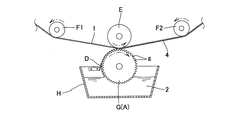
グラビア塗工方式のロール塗工装置(以下、「グラビアコーター」という。)では、図6で示すように、ウェブ1は、導入側ガイドロールF1、及び導出側ガイドレールF2によりガイドされつつ連続的に搬送され、回転する塗工ロールAであるグラビアロールGを、塗工液槽H内の塗工液2に浸漬した後、連続して搬送されるウェブ1に接触させる。グラビアロールG表面には、微細な液溜め用凹部(以下、「セル」ともいう)gが多数形成されており、グラビアロールGを回転させつつ塗工液2に浸漬して、個々のセルに塗工液を充填する。さらに、浸漬の直後に、ドクターブレードDをグラビアロールGの表面に接触させ、余分な塗工液をロール表面から擦り落として、一定量の塗工液がセル内に留まるようにする。さらに、グラビアロールGがウェブに接触する地点で、ウェブを裏面側から押圧ローラEによって高い圧力で押圧する。これにより、毛細管現象及び押圧力によって、セル内の塗工液がウェブ表面に転移され、ウェブ上に精度よく塗工膜を形成することができる(例えば、特許文献1参照)。
In a gravure coating type roll coating apparatus (hereinafter referred to as “gravure coater”), as shown in FIG. 6, the web 1 is continuously guided while being guided by an introduction side guide roll F1 and a lead-out side guide rail F2. After the gravure roll G, which is the coating roll A that is conveyed and rotated, is immersed in the
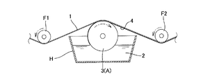
キス塗工方式等のロール塗工装置(以下、「キスコーター」という。)は、図7で示すように、ウェブ1は、導入側ガイドロールF1、及び導出側ガイドレールF2によりガイドされつつ連続的に搬送され、回転する塗工ロールAである、表面に凹凸が形成されていない塗工ロール3を、塗工液槽H内の塗工液2に浸漬した後、連続して搬送されるウェブ1に接触させることで、塗工液をウェブ表面に転移させる。塗工ロール3の表面は、グラビアロールGの表面が有する微細な液溜め用凹部を有しておらず、滑らかな曲面である。キスコーターでは、ロール表面に液溜め用凹部を設けていないことから、グラビアコーターで使用する押圧ローラは使用されていない。
As shown in FIG. 7, a roll coating apparatus such as a kiss coating system (hereinafter referred to as “kiss coater”) continuously guides the web 1 while being guided by an introduction side guide roll F <b> 1 and a lead-out side guide rail F <b> 2. A web that is continuously transported after the
図6に示すグラビアコーターでは、グラビアロールG表面のセルg及びドクターブレードDにより正確に計量された塗工液をウェブに転移させることができるため、精度よく、膜厚が均一な塗工膜を形成することができる。このため、高品質な塗工膜が要求される製品に広く適用することができる。しかしながら、グラビアロールGの表面に、多数の微細なセルをレーザ彫刻、化学的エッチング、機械加工等により形成する必要があるため、設備コストが増大する傾向がある。また、運転過程においてセルの詰まりが発生する恐れがあるため、品質を安定させるためには、頻繁なメンテナンスが必要となる。さらに、ドクターブレードDをグラビアロールGの表面に接触させつつロールを回転させるため、ドクターブレード又はロール表面に摩耗や欠けが発生する恐れがあり、この点でも頻繁なメンテナンスが必要である。さらにまた、セル内の塗工液をウェブ表面に転移させるため、ウェブ上の塗工膜にセルのパターンが転写される恐れもある。 In the gravure coater shown in FIG. 6, the coating liquid accurately measured by the cell g and the doctor blade D on the surface of the gravure roll G can be transferred to the web. Can be formed. For this reason, it can be widely applied to products that require a high-quality coating film. However, since many fine cells need to be formed on the surface of the gravure roll G by laser engraving, chemical etching, machining, or the like, the equipment cost tends to increase. In addition, since there is a risk of cell clogging during the operation process, frequent maintenance is required to stabilize the quality. Furthermore, since the roll is rotated while the doctor blade D is in contact with the surface of the gravure roll G, the doctor blade or the roll surface may be worn or chipped, and frequent maintenance is also required in this respect. Furthermore, since the coating liquid in the cell is transferred to the web surface, the cell pattern may be transferred to the coating film on the web.
一方、図7に示すキスコーターでは、ロール表面にセルを設けておらず、ドクターブレードも使用しないことから、設備コスト及び保守コストを抑制することができ、セルのパターンが転写される問題も発生しない。その反面、グラビアコーターのようにウェブに転移させる塗工液を正確に計量する手段を有していないため、幅方向(搬送方向に対し垂直な方向)において塗工膜の膜厚にバラツキが生じる問題がある。この問題は、特に、生産性向上を目的に高速度でウェブの搬送及び塗工を行う際に顕著になる。 On the other hand, in the kiss coater shown in FIG. 7, since no cells are provided on the roll surface and no doctor blade is used, the equipment cost and the maintenance cost can be suppressed, and the problem that the cell pattern is transferred does not occur. . On the other hand, since there is no means for accurately measuring the coating liquid transferred to the web like a gravure coater, the coating film thickness varies in the width direction (direction perpendicular to the transport direction). There's a problem. This problem is particularly noticeable when the web is conveyed and coated at a high speed for the purpose of improving productivity.
本発明は、上記現状に鑑み、連続して搬送されるウェブに塗工ロールを用いて塗工を施すにあたって、製造コストや保守コストを抑制し、塗工膜にセルのパターンが転写されないという利点を有しながら、幅方向における塗工膜の膜厚のバラツキを抑制することを目的とする。 In view of the above-mentioned present situation, the present invention is advantageous in that, when coating is performed on a continuously conveyed web using a coating roll, the manufacturing cost and maintenance cost are suppressed, and the cell pattern is not transferred to the coating film. The object is to suppress variations in the thickness of the coating film in the width direction.
本発明は、連続して搬送されるウェブに塗工を施すロール塗工装置であって、
塗工液を供給する塗工液供給手段と、
前記塗工液供給手段から供給された塗工液を表面に付着させて回転し、前記搬送されるウェブの一面の全幅に接触することで、当該ウェブの一面の全幅に前記塗工液を転移させる塗工ロールと、
前記ウェブに転移する前の前記塗工液が付着している前記塗工ロールの表面に向けて配置されたブレードと、
前記塗工ロールが前記ウェブの一面に接触する位置で、前記ウェブの他面の全幅を、前記塗工ロールに向かって押圧する押圧手段と、を備え、
前記塗工ロールは、ロール表面に液溜め用凹部を設けていないものであり、
前記ブレードは、前記塗工ロールの表面には接触せず、前記塗工ロールの表面に付着した前記塗工液に、前記ウェブの幅以上の幅にわたって接触するように配置されていることを特徴とする、
ロール塗工装置に関する。
The present invention is a roll coating apparatus for coating a continuously conveyed web,
A coating liquid supply means for supplying the coating liquid;
The coating liquid supplied from the coating liquid supply means is attached to the surface, rotated, and brought into contact with the full width of one side of the conveyed web, thereby transferring the coating liquid to the full width of the one side of the web. A coating roll to make,
A blade disposed toward the surface of the coating roll to which the coating liquid before transferring to the web is attached;
A pressing means for pressing the entire width of the other surface of the web toward the coating roll at a position where the coating roll contacts one surface of the web;
The coating roll is one that does not have a liquid reservoir recess on the roll surface,
The blade is arranged so as not to contact the surface of the coating roll but to contact the coating liquid adhering to the surface of the coating roll over a width greater than the width of the web. And
The present invention relates to a roll coating apparatus.
好ましくは、前記ブレードと前記塗工ロールの表面とのあいだの隙間の幅は、5〜100μmである。 Preferably, the width of the gap between the blade and the surface of the coating roll is 5 to 100 μm.
また本発明は、前記ロール塗工装置を用いて、連続して搬送されるウェブに塗工を施すことを特徴とする、塗工膜が形成されたウェブの製造方法にも関する。 The present invention also relates to a method for producing a web on which a coating film is formed, wherein the roll coating apparatus is used to coat a web that is continuously conveyed.
好ましくは、前記押圧手段により、線圧200N/m未満で前記ウェブの他面を押圧する。 Preferably, the other surface of the web is pressed by the pressing means at a linear pressure of less than 200 N / m.
好ましくは、前記ウェブは、20m/min以上の搬送速度で搬送される。 Preferably, the web is conveyed at a conveyance speed of 20 m / min or more.
本発明に係るロール塗工装置、及び塗工膜が形成されたウェブの製造方法によれば、以下の顕著な効果を有する。
(1)表面に微細なセルを多数設けたグラビアロールも、ロール表面に接触するドクターブレードも使用しないため、製造コスト及び保守コストを抑制することができ、塗工膜にセルのパターンが転写される恐れがなく平坦な塗工膜を形成できる。さらには、頻繁なメンテナンスが不要となるため、連続生産性が高く、連続生産時における品質安定性が高い。
(2)塗工ロールの表面には接触していないものの、塗工ロール表面の塗工液膜に全幅にわたって接触するように配置した近接ブレードを、塗工ロールがウェブに接触する前に設けているため、ウェブへの塗工液の転移前に、塗工ロール上の塗工液膜の厚みを幅方向に均すことができ、その結果、幅方向における塗工膜の膜厚のバラツキを抑制できる。特に高速度でウェブの搬送及び塗工を行う場合においても、幅方向における塗工膜の膜厚のバラツキを抑制できる。
(3)塗工ロールがウェブに接触する位置で、ウェブの裏面を押圧手段によって押圧しながら、塗工液をウェブに転移させるため、連続して搬送されるウェブに対して塗工液膜を幅方向に均一に、所望の厚みで転移させることができる。
The roll coating apparatus according to the present invention and the method for producing a web on which a coating film is formed have the following remarkable effects.
(1) Since neither a gravure roll with many fine cells on its surface nor a doctor blade that contacts the roll surface is used, manufacturing costs and maintenance costs can be reduced, and the cell pattern is transferred to the coating film. Therefore, a flat coating film can be formed. Furthermore, since frequent maintenance is not required, continuous productivity is high, and quality stability during continuous production is high.
(2) Although it is not in contact with the surface of the coating roll, a proximity blade disposed so as to be in contact with the coating liquid film on the surface of the coating roll over the entire width is provided before the coating roll contacts the web. Therefore, before the coating liquid is transferred to the web, the thickness of the coating liquid film on the coating roll can be leveled in the width direction. As a result, the coating film thickness variation in the width direction can be reduced. Can be suppressed. In particular, even when the web is conveyed and coated at a high speed, variations in the thickness of the coating film in the width direction can be suppressed.
(3) In order to transfer the coating liquid to the web while pressing the back surface of the web with the pressing means at the position where the coating roll comes into contact with the web, the coating liquid film is applied to the continuously conveyed web. The film can be transferred uniformly in the width direction with a desired thickness.
以下、本発明について詳細に説明する。 Hereinafter, the present invention will be described in detail.
本発明のロール塗工装置は、帯状のウェブを連続して搬送しながら、ウェブ表面に連続的に塗工を施すための装置であって、少なくとも、塗工液供給手段と、塗工ロールと、ブレードと、押圧手段と、ウェブの搬送装置とを備えている。さらに、ウェブ表面の塗工液を加熱する加熱手段や、ウェブを巻き取る巻取り手段を有していてもよい。 The roll coating apparatus of the present invention is an apparatus for continuously coating a web surface while continuously conveying a belt-shaped web, and includes at least a coating liquid supply means, a coating roll, , A blade, pressing means, and a web conveying device. Furthermore, you may have a heating means which heats the coating liquid of a web surface, and a winding means which winds up a web.
(ウェブ)
本発明におけるウェブは、厚みが均一で可撓性のあるフィルム又はシート状の基材を長尺帯状に形成したものである。前記基材を構成する材料としては特に限定されないが、例えば、樹脂、紙、布、金属等が挙げられ、用途に応じて適宜選択することができる。樹脂の具体例としては、例えば、ポリエチレンテレフタレート、ポリエチレンナフタレート等のポリエステル系ポリマー;ジアセチルセルロース、トリアセチルセルロース等のセルロース系ポリマー;ポリカーボネート系ポリマー;ポリメチルメタクリレート等のアクリル系ポリマー;ポリスチレン、アクリロニトリル−スチレン共重合体等のスチレン系ポリマー;ポリエチレン、ポリプロピレン、環状またはノルボルネン構造を有するポリオレフィン、エチレン−プロピレン共重合体等のオレフィン系ポリマー;塩化ビニル系ポリマー;ナイロン(脂肪族ポリアミド)や芳香族ポリアミド等のアミド系ポリマー;ポリイミド系ポリマー;これらポリマーのブレンド物等が挙げられる。
(web)
The web in the present invention is obtained by forming a flexible film or sheet-like base material having a uniform thickness into a long band shape. Although it does not specifically limit as a material which comprises the said base material, For example, resin, paper, cloth, a metal etc. are mentioned, It can select suitably according to a use. Specific examples of the resin include, for example, polyester polymers such as polyethylene terephthalate and polyethylene naphthalate; cellulose polymers such as diacetyl cellulose and triacetyl cellulose; polycarbonate polymers; acrylic polymers such as polymethyl methacrylate; polystyrene, acrylonitrile- Styrene polymers such as styrene copolymers; polyethylene, polypropylene, polyolefins having a cyclic or norbornene structure, olefin polymers such as ethylene-propylene copolymers; vinyl chloride polymers; nylon (aliphatic polyamide), aromatic polyamides, etc. Amide polymers; polyimide polymers; blends of these polymers, and the like.
(塗工液供給手段)
本発明における塗工液供給手段とは、図1〜3で示す場合には所要量の塗工液を貯留する塗工液槽2であるか、又は、図4で示す場合には塗工液槽2及び汲み上げロール10である。塗工ロールの下部又は汲み上げロール10の下部を塗工液槽内の塗工液に浸漬できるよう、塗工液槽は、その上部に、塗工ロールの下部又は汲み上げロール10の下部が進入することができる開放部を有している。
(Coating liquid supply means)
The coating liquid supply means in the present invention is the
本発明における塗工液は、ウェブへの塗工後に乾燥、硬化等を行なって塗工膜を形成しうる樹脂液である。該塗工液に含まれる樹脂材料については特に限定されず、例えば、ポリウレタン、ポリシクロオレフィン、ポリカーボネート、ポリエステル、ポリエーテルケトン、ポリアミド、ポリイミド、ポリアミド−イミド又はポリエステル−イミド等の各種ポリマーを挙げることができる。これらのポリマーは、いずれか一種類を単独で使用しても良いし、例えば、ポリエーテルケトンとポリアミドとの混合物のように、異なる官能基を持つ2種類以上の混合物として使用してもよい。さらには、カーボンブラック、金属、セラミクス等のフィラーが混合されていても良い。乾燥、硬化の条件は特に限定されず、一般的な条件であってよい。また、これらの材料を硬化させる際には、乾燥固化、熱硬化、紫外線硬化など、材料に応じた硬化工程を選択することができる。 The coating liquid in the present invention is a resin liquid capable of forming a coating film by drying, curing and the like after coating on a web. The resin material contained in the coating solution is not particularly limited, and examples thereof include various polymers such as polyurethane, polycycloolefin, polycarbonate, polyester, polyether ketone, polyamide, polyimide, polyamide-imide, and polyester-imide. Can do. Any one of these polymers may be used alone, or for example, a mixture of two or more kinds having different functional groups such as a mixture of polyetherketone and polyamide. Furthermore, fillers such as carbon black, metal, and ceramics may be mixed. Drying and curing conditions are not particularly limited, and may be general conditions. Moreover, when hardening these materials, the hardening process according to materials, such as drying solidification, thermosetting, and ultraviolet curing, can be selected.
前記樹脂液は、前記樹脂材料を溶解させる溶剤、又は、前記樹脂材料を分散させる分散媒を含有することができる。そのような溶媒又は分散媒としては特に限定されず、使用する樹脂材料及びウェブに応じ適宜選択することができる。具体的には、例えば、クロロホルム、ジクロロメタン、四塩化炭素、ジクロロエタン、テトラクロロエタン、トリクロロエチレン、テトラクロロエチレン、クロロベンゼン、o−ジクロロベンゼン等のハロゲン化炭化水素類;フェノール、p−クロロフェノール等のフェノール類;メタノール、エタノール等のアルコール類;ベンゼン、トルエン、キシレン、メトキシベンゼン、1,2−ジメトキシベンゼン等の芳香族炭化水素類;アセトン、酢酸エチル、t−ブチルアルコール、グリセリン、エチレングリコール、トリエチレングリコール、エチレングリコールモノメチルエーテル、ジエチレングリコールジメチルエーテル、プロピレングリコール、ジプロピレングリコール、2−メチル−2,4−ペンタンジオール、エチルセルソルブ、ブチルセルソルブ、2−ピロリドン、N−メチル−2−ピロリドン、ピリジン、トリエチルアミン、ジメチルホルムアミド、ジメチルアセトアミド、アセトニトリル、ブチロニトリル、メチルイソブチルケトン、メチルエーテルケトン、シクロヘキサン、シクロペンタノン、二硫化炭素、水等を用いることができる。これら溶剤又は分散媒は、1種又は2種以上を適宜組み合わせて使用することができる。 The resin liquid may contain a solvent that dissolves the resin material or a dispersion medium that disperses the resin material. Such a solvent or dispersion medium is not particularly limited, and can be appropriately selected according to the resin material and web to be used. Specifically, for example, halogenated hydrocarbons such as chloroform, dichloromethane, carbon tetrachloride, dichloroethane, tetrachloroethane, trichloroethylene, tetrachloroethylene, chlorobenzene, o-dichlorobenzene; phenols such as phenol and p-chlorophenol; methanol Alcohols such as ethanol; aromatic hydrocarbons such as benzene, toluene, xylene, methoxybenzene, 1,2-dimethoxybenzene; acetone, ethyl acetate, t-butyl alcohol, glycerin, ethylene glycol, triethylene glycol, ethylene Glycol monomethyl ether, diethylene glycol dimethyl ether, propylene glycol, dipropylene glycol, 2-methyl-2,4-pentanediol, ethyl cellosolve, Use tilselsolve, 2-pyrrolidone, N-methyl-2-pyrrolidone, pyridine, triethylamine, dimethylformamide, dimethylacetamide, acetonitrile, butyronitrile, methyl isobutyl ketone, methyl ether ketone, cyclohexane, cyclopentanone, carbon disulfide, water, etc. be able to. These solvents or dispersion media can be used alone or in combination of two or more.
(塗工ロール)
本発明における塗工ロールは、前記塗工液供給手段から塗工液を供給されて、その表面に塗工液を付着させて回転し、ウェブに接触して、ウェブに塗工液を転移させる回転体である。本発明における塗工ロールは、グラビアロールが有する微細な液溜め用凹部をロール表面に有しておらず、ロール表面は滑らかに成形されている。塗工ロールは、その幅が、ウェブの幅よりも大きく、ウェブの全幅に接触し、ウェブの全幅に塗工液を転移させることができる。
(Coating roll)
The coating roll in the present invention is supplied with the coating liquid from the coating liquid supply means, rotates with the coating liquid attached to the surface thereof, contacts the web, and transfers the coating liquid to the web. It is a rotating body. The coating roll in the present invention does not have the fine liquid reservoir recesses of the gravure roll on the roll surface, and the roll surface is smoothly formed. The width of the coating roll is larger than the width of the web, and the coating roll can contact the entire width of the web and transfer the coating solution to the entire width of the web.
図1で示すように、塗工ロールを塗工液槽2内の塗工液に浸漬して、塗工液槽2から塗工ロールに直接塗工液が供給されてもよいし、図4で示すように、塗工ロールを塗工液槽2内の塗工液に浸漬せず、塗工液槽2内の塗工液に浸漬した汲み上げロール10と塗工ロールが接触回転して、当該汲み上げロール10を通じて塗工液が塗工ロールに供給されてもよい。
As shown in FIG. 1, the coating roll may be immersed in the coating liquid in the
(ブレード)
本発明におけるブレードは、その先端が、ウェブに転移する前の塗工液が付着している塗工ロールの表面に向けて配置されている。本発明におけるブレードは、グラビアコーターで使用するドクターブレードとは異なって、塗工ロールの表面には接触していない。しかし、塗工ロールに近接して配置されており、塗工ロール表面に付着している塗工液に接触する程度に、塗工ロールとの間に隙間を設けて配置されている。そのため、本発明のブレードは、「近接ブレード」ともいうことができる。近接ブレードは、その先端部の幅がウェブの幅よりも大きいと共に、前記ウェブの幅以上の幅にわたって塗工ロール表面の塗工液に接触して、塗工ロール表面の塗工液膜の厚みを均すことができる。
(blade)
The tip of the blade in the present invention is arranged toward the surface of the coating roll to which the coating liquid before transferring to the web is attached. Unlike the doctor blade used in the gravure coater, the blade in the present invention is not in contact with the surface of the coating roll. However, it is disposed in the vicinity of the coating roll and is disposed with a gap between the coating roll and the coating roll so as to come into contact with the coating liquid adhering to the coating roll surface. Therefore, the blade of the present invention can also be referred to as a “proximity blade”. The proximity blade has a width of the tip portion larger than the width of the web and contacts the coating liquid on the surface of the coating roll over the width of the web or more, and the thickness of the coating liquid film on the surface of the coating roll Can be leveled.
近接ブレードは、塗工ロール表面の塗工液膜の厚みを均一化することが目的であるので、近接ブレードと塗工ロールとの間の隙間の幅は、幅方向に一定になるように設定されている。また、近接ブレードは、少なくとも、次の段階でウェブに塗工液が転移される幅分の塗工液膜において、その厚みを均すことになるが、塗工ロールの全幅にわたって塗工液膜の厚みを均すことができるように構成されることが好ましい。 The proximity blade is intended to make the thickness of the coating film on the coating roll surface uniform, so the width of the gap between the proximity blade and the coating roll is set to be constant in the width direction. Has been. In addition, the proximity blade, at least in the coating liquid film of the width that the coating liquid is transferred to the web in the next stage, will equalize its thickness, but the coating liquid film over the entire width of the coating roll It is preferable to be configured so that the thickness can be equalized.
近接ブレードの形状は特に限定されない。例えばグラビアコーターで使用するドクターブレードを、本発明における近接ブレードとして使用することができる。近接ブレードを構成する材料も特に限定されず、例えば、金属、樹脂、FRP、ゴム等が挙げられる。 The shape of the proximity blade is not particularly limited. For example, a doctor blade used in a gravure coater can be used as a proximity blade in the present invention. The material constituting the proximity blade is not particularly limited, and examples thereof include metal, resin, FRP, and rubber.
近接ブレードはいずれかの端部に保持部を設け、この保持部によって近接ブレードを支持する。近接ブレードは、送りねじ、エアシリンダ等の推力を用いて移動可能なように配置される。これにより、近接ブレードと塗工ロールとの間の隙間の幅を任意に設定することができる。 The proximity blade is provided with a holding portion at either end, and the proximity blade is supported by the holding portion. The proximity blade is disposed so as to be movable using a thrust such as a feed screw or an air cylinder. Thereby, the width | variety of the clearance gap between a proximity | contact blade and a coating roll can be set arbitrarily.
近接ブレードと塗工ロールとの間の隙間の幅は特に限定されず、塗工ロール表面での塗工液膜の厚みや、塗工液の粘度、塗工ロールの回転方向に対する近接ブレードの角度等を考慮して適宜設定することができる。しかし、隙間の幅が大きくなりすぎると、塗工ロール表面に付着している塗工液膜の厚みを均す効果が得られにくくなるため、その点を勘案して隙間の幅を決定することが好ましい。具体的には、前記隙間の幅は200μm未満が好ましく、180μm以下がより好ましく、150μm以下がさらに好ましく、100μm以下が特に好ましい。下限値は特に限定されないが、前記隙間の幅が小さくなりすぎると近接ブレードと塗工ロールが接触する可能性が生じるため、1μm以上が好ましく、3μm以上がより好ましく、5μm以上がさらに好ましい。 The width of the gap between the proximity blade and the coating roll is not particularly limited. The thickness of the coating liquid film on the surface of the coating roll, the viscosity of the coating liquid, and the angle of the proximity blade with respect to the rotation direction of the coating roll. Etc. can be set as appropriate. However, if the width of the gap becomes too large, it will be difficult to obtain the effect of leveling the thickness of the coating liquid film adhering to the coating roll surface. Is preferred. Specifically, the width of the gap is preferably less than 200 μm, more preferably 180 μm or less, further preferably 150 μm or less, and particularly preferably 100 μm or less. The lower limit is not particularly limited, but if the width of the gap becomes too small, the proximity blade and the coating roll may come into contact with each other, preferably 1 μm or more, more preferably 3 μm or more, and even more preferably 5 μm or more.
(押圧手段)
本発明における押圧手段は、塗工ロールがウェブに接触する位置で、ウェブの裏面に接触して、当該裏面を塗工ロールに向かって押圧するものである。これにより、塗工液膜を、所望の厚みで、幅方向に均一にウェブ上に転移させることができる。押圧手段は、塗工液膜を幅方向に均一に転移させるため、ウェブの全幅にわたって同じ押圧でウェブの裏面を押圧する。
(Pressing means)
In the present invention, the pressing means contacts the back surface of the web at a position where the coating roll contacts the web and presses the back surface toward the coating roll. Thereby, the coating liquid film can be uniformly transferred on the web in the width direction with a desired thickness. The pressing means presses the back surface of the web with the same pressing over the entire width of the web in order to uniformly transfer the coating liquid film in the width direction.
ウェブ表面に転移される塗工液膜の厚みは、実質的に、この押圧手段による押圧力によって決定される。押圧手段によって、所望の厚みの塗工液膜をウェブの幅方向に均一に転移させる観点から、塗工液の粘性や表面張力等を勘案して、押圧力を適宜決定することができる。しかし、従来のグラビアコーターではセル内の塗工液をウェブに転写するため、押圧手段による押圧力は高く設定する必要があったが、本発明では、塗工ロールが滑らかな表面を有するもので、押圧手段による押圧力はグラビアコーターほど高くする必要はない。逆に押圧力が高くなりすぎると、塗工抜け又は裏回りが発生する恐れがある。この観点から、本発明では押圧手段による押圧力は、線圧で200N/m未満に設定することが好ましく、150N/m以下がより好ましく、100N/m以下がさらに好ましい。また、前記押圧力は低すぎると、ウェブに転移する塗工液膜の厚みの均一化を図るという効果が得られにくくなるので、線圧で30N/m以上に設定することが好ましく、40N/m以上がより好ましく、50N/m以上がさらに好ましい。 The thickness of the coating liquid film transferred to the web surface is substantially determined by the pressing force by the pressing means. From the viewpoint of uniformly transferring the coating liquid film having a desired thickness in the width direction of the web by the pressing means, the pressing force can be appropriately determined in consideration of the viscosity and surface tension of the coating liquid. However, in the conventional gravure coater, since the coating liquid in the cell is transferred to the web, it is necessary to set the pressing force by the pressing means to be high, but in the present invention, the coating roll has a smooth surface. The pressing force by the pressing means does not need to be as high as that of the gravure coater. On the other hand, if the pressing force becomes too high, coating omission or reverse may occur. From this viewpoint, in the present invention, the pressing force by the pressing means is preferably set to a linear pressure of less than 200 N / m, more preferably 150 N / m or less, and even more preferably 100 N / m or less. Further, if the pressing force is too low, it becomes difficult to obtain the effect of uniforming the thickness of the coating liquid film transferred to the web. Therefore, the linear pressure is preferably set to 30 N / m or more, and 40 N / m m or more is more preferable, and 50 N / m or more is more preferable.
押圧手段の具体的な構成としては、ウェブの全幅を塗工ローラに向かって押圧できるものであれば特に限定されず、押圧ロール、押圧板等の接触式の押圧手段であってもよいし、空気や窒素等の気体の圧力を利用して押圧する非接触式の押圧手段であってもよい。 The specific configuration of the pressing means is not particularly limited as long as it can press the entire width of the web toward the coating roller, and may be a contact-type pressing means such as a pressing roll or a pressing plate, Non-contact type pressing means that presses using the pressure of a gas such as air or nitrogen may be used.
押圧ロールを構成する材料としては特に限定されず、金属、樹脂、ゴム等のいずれか1種類であってもよく、あるいは複数の組み合わせであってもよい。押圧ロールは、ロール表面に弾性層を有する弾性ロールであることが好ましい。前記弾性層を形成する弾性体としては特に限定されないが、例えば、天然ゴム、スチレンブダジエンゴム、ニトリルゴム、クロロプレンゴム、ブチルゴム、エチレンプロピレンゴム、シリコンゴム、フッ素ゴム、ウレタンゴム等が挙げられる。 It does not specifically limit as a material which comprises a press roll, Any one types, such as a metal, resin, rubber | gum, may be sufficient, or several combinations may be sufficient. The pressing roll is preferably an elastic roll having an elastic layer on the roll surface. The elastic body forming the elastic layer is not particularly limited, and examples thereof include natural rubber, styrene butadiene rubber, nitrile rubber, chloroprene rubber, butyl rubber, ethylene propylene rubber, silicon rubber, fluorine rubber, and urethane rubber.
(搬送装置)
本発明のロール塗工装置は、ウェブを連続して搬送するための搬送装置をさらに有するものである。ウェブを搬送する速度は特に限定されないが、低速であっても高速であっても本発明の効果が得られる。従来法では例えば10m/min以上という高速で搬送した場合に特に幅方向における塗工膜の膜厚のバラツキという問題が発生しやすかったが、本発明によると、このような高速搬送の場合でも塗工膜の膜厚のバラツキを抑制することができる。本発明における搬送速度は10m/min以上が好ましく、15m/min以上がより好ましく、20m/min以上がさらに好ましい。
(Transport device)
The roll coating apparatus of the present invention further includes a transport device for continuously transporting the web. The speed at which the web is conveyed is not particularly limited, but the effect of the present invention can be obtained at a low speed or a high speed. In the conventional method, for example, when the film is conveyed at a high speed of 10 m / min or more, the problem of uneven coating film thickness in the width direction is likely to occur. According to the present invention, the coating is performed even in such a high-speed conveyance. Variations in the film thickness of the film can be suppressed. The conveyance speed in the present invention is preferably 10 m / min or more, more preferably 15 m / min or more, and further preferably 20 m / min or more.
また、本発明のロール塗工装置は、ウェブに塗工液を転移させた後に、塗工液を乾燥又は硬化させるための加熱手段をさらに有していてもよく、塗工膜が形成されたウェブを巻き取るための巻取り手段をさらに有していてもよい。 Moreover, the roll coating apparatus of the present invention may further have a heating means for transferring or drying the coating liquid after transferring the coating liquid to the web, and the coating film is formed. You may have further the winding-up means for winding up a web.
(製造方法)
本発明のロール塗工装置を稼働させることにより、帯状のウェブを連続して搬送しながら、ウェブ表面に連続的に塗工を施すことができる。本発明の製造方法によると、まず、塗工液が塗工液供給手段から塗工ロールに供給されて、塗工ロールは塗工液を表面に付着させて回転する。次いで、回転している塗工ロール表面に付着している塗工液は近接ブレードに接触して、塗工液膜の厚みがウェブの幅方向に均一化される。厚みが均一化された塗工液膜を表面に有する塗工ロールはさらに回転を続け、ウェブに接触するが、その接触位置でのウェブ裏面は押圧手段によって押圧される。以上の各工程を連続的に行うことで、塗工液膜を、連続的に、幅方向に均一な厚みでウェブ上に転移させることができる。
(Production method)
By operating the roll coating apparatus of the present invention, the web surface can be continuously coated while the belt-like web is continuously conveyed. According to the production method of the present invention, first, the coating liquid is supplied from the coating liquid supply means to the coating roll, and the coating roll rotates with the coating liquid attached to the surface. Next, the coating liquid adhering to the rotating coating roll surface comes into contact with the proximity blade, and the thickness of the coating liquid film is made uniform in the web width direction. The coating roll having a coating liquid film with a uniform thickness on the surface continues to rotate and contacts the web, but the back surface of the web at the contact position is pressed by the pressing means. By continuously performing the above steps, the coating liquid film can be continuously transferred onto the web with a uniform thickness in the width direction.
(第一実施形態)
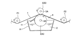
図1は、本発明の一実施形態に係るロール塗工装置の構成を示す縦断面図である。ここでは、塗工液槽H内の塗工液2に浸漬して回転する塗工ロールAである、表面に液溜め用凹部が無い塗工ロール3から、連続して搬送されるウェブ1に塗工液を転移させ、ウェブ1の下面に塗工液膜4を形成している。
(First embodiment)
FIG. 1 is a longitudinal sectional view showing a configuration of a roll coating apparatus according to an embodiment of the present invention. Here, the web 1 is continuously conveyed from the
ウェブ1は、導入側ガイドロールF1、塗工ロール3、及び導出側ガイドレールF2に、この順で接触するように案内される。ウェブ1と導入側ガイドロールF1の接触面、及び、ウェブ1と導出側ガイドレールF2の接触面が、ウェブ1と塗工ロール3との接触面よりも鉛直方向で下になるように、各ロールは配置される。この配置によって、ウェブ1は、図1で示すように塗工ロール3との接触面が上に突き出しているような経路で案内される。
The web 1 is guided so as to come into contact with the introduction-side guide roll F1, the
塗工ロール3の回転方向に沿って説明すると、塗工ロール3は、塗工液槽H内の塗工液2に潜水して当該塗工液内を移動した後、当該塗工液2から浮上する。浮上した塗工ロール3表面には、塗工液が付着している。塗工液が付着した塗工ロール3表面に向けて、近接ブレード11が塗工ロール3の回転方向と垂直に配置されている。近接ブレード11が塗工ロール3表面に付着している塗工液に接触することで、ロール表面の塗工液膜の厚みが幅方向に均される。その後、塗工ロール3表面がウェブ1の下面に接触するが、その裏面(上面)が、押圧手段Bである押圧ロール5に接触している。塗工ロール3と押圧ロール5はウェブ1を挟み込むように配置されており、塗工ロール3及び押圧ロール5の幅はウェブ1の幅よりも大きく、ウェブ1の全幅が塗工ロール3及び押圧ロール5により挟み込まれている。押圧ロール5は、塗工ロール3とは反対方向に回転しながら、ウェブ1を押圧する。これにより、塗工ロール3表面の塗工液がウェブに転移される。
Explaining along the rotation direction of the
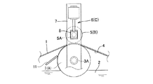
図2は、本発明の一実施形態に係るロール塗工装置における塗工ロール及び押圧ロールの具体的構成の一例を示す縦断面図である。ここでは、押圧ロール5による押圧力を調整するための調整手段Cを設けている。固定部材であるフレーム7は、塗工ロール3の回転軸3Aを軸受(図示せず)により支持している。さらにフレーム7は、押圧ロール5の回転軸5Aを軸受(図示せず)により支持する軸支持体8を上下方向にスライド可能に支持している。軸支持体8は、調整手段Cであるエアシリンダ6によって上下方向に駆動可能とされている。押圧ロール5は、その軸受及び軸支持体8を含む自重、並びにエアシリンダ6の推力により、塗工ロール3及びウェブ1に向かって押し付けられている。エアシリンダ6の推力を調整することにより、押圧ロール5による押圧力を調整することができる。
FIG. 2 is a longitudinal sectional view showing an example of a specific configuration of the coating roll and the pressing roll in the roll coating apparatus according to the embodiment of the present invention. Here, an adjusting means C for adjusting the pressing force by the
エアシリンダ6は複動形を採用し、例えば、前記自重(W)以上の押圧力を加えたい場合には、エアシリンダ6のロッドにより下方へ推力(F)を発生させることにより、前記自重(W)に推力(F)が加わった合力(W+F)をウェブ1に作用させることができる。逆に前記自重(W)より小さい押圧力を加えたい場合には、エアシリンダ6のロッドにより上方へ推力(F)を発生させることにより、前記自重(W)から推力(F)を引いた力(W−F)をウェブ1に作用させることができる。そして、エアシリンダ6に供給する空気圧を調整することにより、推力(F)の大きさを調整することができる。このように、押圧力の調整手段Cをエアシリンダ6で構成することにより、例えば工場内のエア設備を利用して押圧力の調整手段Cを簡素にかつ確実に構成することができる。
The
(第二実施形態)
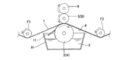
図3は、本発明の別の実施形態に係るロール塗工装置の構成を示す縦断面図である。この実施形態では、押圧ロール5の上部に、押圧ロール5と接触して反対方向に回転するバックアップロール9を備えており、この点以外は図1で示した実施形態と同じである。このバックアップロール9により、押圧ロール5の撓みを防止することができる。バックアップロール9は、押圧ロール5の撓みを防止できるよう押圧ロール5に圧力をかけられるロールである限り、その具体的な構成は特に限定されない。
(Second embodiment)
FIG. 3 is a longitudinal sectional view showing a configuration of a roll coating apparatus according to another embodiment of the present invention. In this embodiment, a backup roll 9 that rotates in the opposite direction in contact with the
(第三実施形態)
図4は、本発明のさらに別の実施形態に係るロール塗工装置の構成を示す縦断面図である。この実施形態では、塗工ロール3の下部に、塗工ロール3と接触して反対方向に回転する汲み上げロール10を備えている。ここでは、塗工ロール3は塗工液槽H内の塗工液2に潜水せず、代りに、汲み上げロール10が潜水し、その後、浮上する。浮上した汲み上げロール10の表面に付着した塗工液は、汲み上げロール10と塗工ロール3の接触によって、塗工ロール3の表面に転移される。その後は、図1で示した実施形態と同じである。汲み上げロール10としては、塗工ロール3と同様、グラビアロールが有する微細な液溜め用凹部を表面に有しておらず、表面が滑らかに成形されているロールを使用することができる。
(Third embodiment)
FIG. 4 is a longitudinal sectional view showing a configuration of a roll coating apparatus according to still another embodiment of the present invention. In this embodiment, a pumping
本発明のロール塗工装置、及び塗工膜が形成されたウェブの製造方法は、光学フィルム、磁気記録テープ、接着テープ、写真用印画紙、オフセット版材、電池極板、燃料電池触媒層等の各製造において好適に用いることができる。光学フィルムの一例としては、ウェブ上に、接着層、反射防止層、屈折率調整層、及び防眩層を有する光学フィルムが挙げられる。 The roll coating apparatus of the present invention and the method for producing a web on which a coating film is formed include an optical film, a magnetic recording tape, an adhesive tape, a photographic printing paper, an offset plate material, a battery electrode plate, a fuel cell catalyst layer, and the like. It can use suitably in each manufacture. An example of the optical film includes an optical film having an adhesive layer, an antireflection layer, a refractive index adjusting layer, and an antiglare layer on the web.
以下に実施例を掲げて本発明をさらに詳細に説明するが、本発明はこれら実施例に限定されるものではない。 The present invention will be described in more detail with reference to the following examples, but the present invention is not limited to these examples.
以下の実施例及び比較例では、ロール塗工装置でウェブに連続的に塗工を施し、形成された塗工膜を評価した。 In the following Examples and Comparative Examples, the web was continuously coated with a roll coating apparatus, and the formed coating film was evaluated.
(ロール塗工装置)
図1に示す構成のロール塗工装置を使用した。塗工ロールとしては、表面にハードクロムめっきを施した炭素鋼製ロールであって直径が180mmで幅が400mmのロールを使用し、押圧ロールとしては、直径が60mmで幅が400mmのゴムロールを使用した。近接ブレードとしては、幅が390mm、先端の厚みが0.2mm、材質がSUS420の板状のブレードを使用した。
(Roll coating device)
A roll coating apparatus having the configuration shown in FIG. 1 was used. The coating roll is a carbon steel roll with hard chrome plating on the surface, and a roll with a diameter of 180 mm and a width of 400 mm is used. As a pressing roll, a rubber roll with a diameter of 60 mm and a width of 400 mm is used. did. As the proximity blade, a plate-like blade having a width of 390 mm, a tip thickness of 0.2 mm, and a material of SUS420 was used.
(ウェブ)
ウェブとしては、厚み40μm、幅350mmのアクリルフィルムを用いた。
(web)
As the web, an acrylic film having a thickness of 40 μm and a width of 350 mm was used.
(塗工液)
水系ウレタン樹脂(第一工業製薬株式会社製、商品名:スーパーフレックス210、固形分:33%)200gに対して、架橋剤(株式会社日本触媒製、商品名:エポクロスWS700、固形分:25%)40gを添加して攪拌し、塗工液を得た。
(Coating fluid)
Cross-linking agent (trade name: EPOCROSS WS700, manufactured by Nippon Shokubai Co., Ltd., solid content: 25%) with respect to 200 g of water-based urethane resin (Daiichi Kogyo Seiyaku Co., Ltd., trade name: Superflex 210, solid content: 33%) 40 g was added and stirred to obtain a coating solution.
<実施例及び比較例>
(実施例1)
近接ブレードと塗工ロールのあいだの隙間の幅が、ウェブの幅方向の全幅にわたって5μmになるように両者を配置し、ウェブの搬送速度を20m/minに、押圧ロールの押圧力を線圧100N/mに設定して連続的に塗工を行った。その後、乾燥させて、片面に、長さが約50mの塗工膜が形成されたウェブを得た。
<Examples and Comparative Examples>
Example 1
Both are arranged so that the width of the gap between the adjacent blade and the coating roll is 5 μm over the entire width in the width direction of the web, the web conveyance speed is set to 20 m / min, and the pressing force of the pressing roll is set to a linear pressure of 100 N. The coating was continuously performed at a setting of / m. Then, it was made to dry and the web by which the coating film about 50 m in length was formed on one side was obtained.
(実施例2)
近接ブレードと塗工ロールのあいだの隙間の幅を50μmに変更した以外は実施例1と同様にして、片面に塗工膜が形成されたウェブを得た。
(Example 2)
A web having a coating film formed on one side was obtained in the same manner as in Example 1 except that the width of the gap between the proximity blade and the coating roll was changed to 50 μm.
(実施例3)
近接ブレードと塗工ロールのあいだの隙間の幅を100μmに変更した以外は実施例1と同様にして、片面に塗工膜が形成されたウェブを得た。
(Example 3)
A web with a coating film formed on one side was obtained in the same manner as in Example 1 except that the width of the gap between the proximity blade and the coating roll was changed to 100 μm.
(比較例1)
近接ブレードを使用しなかった以外は実施例1と同様にして、片面に塗工膜が形成されたウェブを得た。
(Comparative Example 1)
A web having a coating film formed on one side was obtained in the same manner as in Example 1 except that the proximity blade was not used.
<評価試験方法>
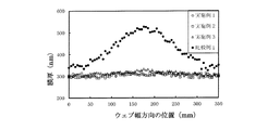
各実施例及び比較例で得られた、片面に塗工膜が形成されたウェブについて、幅方向(搬送方向に対して垂直な方向)における塗工膜の膜厚分布を測定した。塗工膜の膜厚分布の測定は、塗工開始点から40mの地点で、フィルメトリクス株式会社製のF20を使用して分光干渉法により行った。得られた結果を図5に示した。
<Evaluation test method>
About the web in which the coating film was formed in the single side | surface obtained in each Example and the comparative example, the film thickness distribution of the coating film in the width direction (perpendicular to a conveyance direction) was measured. The film thickness distribution of the coating film was measured by spectral interference using a F20 manufactured by Filmetrics Co., Ltd. at a point 40 m from the coating start point. The obtained results are shown in FIG.
<評価試験結果>
実施例1〜3では、いずれも、塗工膜の膜厚は、ウェブの全幅にわたってほぼ均一であり、最大膜厚と最小膜厚の差がわずか約30nmにすぎない。これら実施例では、近接ブレードを、塗工ロール表面の塗工液膜に、全幅にわたって接触するように配置しているため、ロール中央部での塗工液付着量とロール両端部での塗工液付着量との均一化が図られ、その結果、塗工膜の膜厚を均一にすることができたと考えられる。
<Evaluation test results>
In each of Examples 1 to 3, the coating film thickness is almost uniform over the entire width of the web, and the difference between the maximum film thickness and the minimum film thickness is only about 30 nm. In these examples, the proximity blade is disposed so as to be in contact with the coating liquid film on the surface of the coating roll over the entire width, so that the coating liquid adhesion amount at the center of the roll and the coating at both ends of the roll are applied. It is considered that the liquid adhesion amount was made uniform, and as a result, the coating film thickness could be made uniform.
一方、比較例1では、実施例1〜3と比較すると、ウェブの全幅にわたって塗工膜の膜厚が増加しており、また、明らかに、ウェブの中央部における膜厚がウェブの両端部における膜厚よりも大きく、最大膜厚と最小膜厚の差が約200μmもあった。これは、比較例1では近接ブレードを使用していないため、塗工ロールに対する塗工液付着量が、ロール両端部よりもロール中央部において多くなってしまい、結果、ウェブ中央部での塗工液の転移量が、ウェブ両端部でのそれよりも多くなってしまうためと考えられる。 On the other hand, in Comparative Example 1, as compared with Examples 1 to 3, the film thickness of the coating film is increased over the entire width of the web, and obviously, the film thickness at the center of the web is at the both ends of the web. It was larger than the film thickness, and the difference between the maximum film thickness and the minimum film thickness was about 200 μm. This is because the proximity blade is not used in Comparative Example 1, so that the coating liquid adhesion amount to the coating roll is larger at the roll center than at both ends of the roll, and as a result, the coating at the web center is performed. This is thought to be because the amount of liquid transfer is greater than that at both ends of the web.
なお、ウェブの搬送を低速で行う場合には、比較例1のように近接ブレードを使用しなくとも押圧ロールのみを使用することで、塗工膜の膜厚の均一化を図ることは可能である。しかし、比較例1では搬送速度が20m/minと高速でウェブを搬送しているため、押圧ロールのみでは、塗工膜の膜厚の均一化を図ることができなかったものと考えられる。 When the web is transported at a low speed, the thickness of the coating film can be made uniform by using only the pressing roll without using the proximity blade as in Comparative Example 1. is there. However, in Comparative Example 1, since the web is conveyed at a high speed of 20 m / min, it is considered that the thickness of the coating film cannot be uniformed only by the pressing roll.
また、実施例1〜3では、近接ブレードと塗工ロールのあいだの隙間の幅が5〜100μmと大きく異なっているが、形成される塗工膜の膜厚はいずれも300nm程度と同程度であり、前記隙間の幅の大きさが最終的な塗工膜の膜厚に影響していないことが分かる。最終的な塗工膜の膜厚は、近接ブレード後の押圧ロールによる押圧によって調節されているためである。 Moreover, in Examples 1-3, although the width | variety of the clearance gap between a proximity | contact blade and a coating roll is significantly different with 5-100 micrometers, the film thickness of the coating film formed is about 300 nm and all are comparable. It can be seen that the width of the gap does not affect the final film thickness. This is because the final coating film thickness is adjusted by pressing with a pressing roll after the proximity blade.
1 ウェブ
2 塗工液
3 表面が滑らかな塗工ロール
3A 回転軸
4 塗工液膜
5 押圧ロール
5A 回転軸
6 エアシリンダ
7 フレーム
8 軸支持体
9 バックアップロール
10 汲み上げロール
11 近接ブレード
A 塗工ロール
B 押圧手段
C 押圧力の調整手段
D ドクターブレード
E 押圧ロール
F 推力
F1,F2 ガイドロール
G グラビアロール
g 液溜め用凹部
H 塗工液槽
W 自重
DESCRIPTION OF SYMBOLS 1
Claims (5)
塗工液を供給する塗工液供給手段と、
前記塗工液供給手段から供給された塗工液を表面に付着させて回転し、前記搬送されるウェブの一面の全幅に接触することで、当該ウェブの一面の全幅に前記塗工液を転移させる塗工ロールと、
前記ウェブに転移する前の前記塗工液が付着している前記塗工ロールの表面に向けて配置されたブレードと、
前記塗工ロールが前記ウェブの一面に接触する位置で、前記ウェブの他面の全幅を、前記塗工ロールに向かって押圧する押圧手段と、を備え、
前記塗工ロールは、ロール表面に液溜め用凹部を設けていないものであり、
前記ブレードは、前記塗工ロールの表面には接触せず、前記塗工ロールの表面に付着した前記塗工液に、前記ウェブの幅以上の幅にわたって接触するように配置されていることを特徴とする、
ロール塗工装置。 A roll coating apparatus that coats a continuously conveyed web,
A coating liquid supply means for supplying the coating liquid;
The coating liquid supplied from the coating liquid supply means is attached to the surface, rotated, and brought into contact with the full width of one side of the conveyed web, thereby transferring the coating liquid to the full width of the one side of the web. A coating roll to make,
A blade disposed toward the surface of the coating roll to which the coating liquid before transferring to the web is attached;
A pressing means for pressing the entire width of the other surface of the web toward the coating roll at a position where the coating roll contacts one surface of the web;
The coating roll is one that does not have a liquid reservoir recess on the roll surface,
The blade is arranged so as not to contact the surface of the coating roll but to contact the coating liquid adhering to the surface of the coating roll over a width greater than the width of the web. And
Roll coating equipment.
The said web is a manufacturing method of the web in which the coating film of Claim 3 or 4 formed in the conveyance speed of 20 m / min or more was formed.
Priority Applications (1)
| Application Number | Priority Date | Filing Date | Title |
|---|---|---|---|
| JP2016106197A JP2017209652A (en) | 2016-05-27 | 2016-05-27 | Roll coating device, and method for manufacturing film-coated web |
Applications Claiming Priority (1)
| Application Number | Priority Date | Filing Date | Title |
|---|---|---|---|
| JP2016106197A JP2017209652A (en) | 2016-05-27 | 2016-05-27 | Roll coating device, and method for manufacturing film-coated web |
Publications (1)
| Publication Number | Publication Date |
|---|---|
| JP2017209652A true JP2017209652A (en) | 2017-11-30 |
Family
ID=60475111
Family Applications (1)
| Application Number | Title | Priority Date | Filing Date |
|---|---|---|---|
| JP2016106197A Pending JP2017209652A (en) | 2016-05-27 | 2016-05-27 | Roll coating device, and method for manufacturing film-coated web |
Country Status (1)
| Country | Link |
|---|---|
| JP (1) | JP2017209652A (en) |
Cited By (2)
| Publication number | Priority date | Publication date | Assignee | Title |
|---|---|---|---|---|
| CN114392887A (en) * | 2022-01-12 | 2022-04-26 | 湖州金洁包装有限公司 | Scraper for aluminum foil surface coating device |
| CN115069480A (en) * | 2022-02-28 | 2022-09-20 | 上海福赛特智能设备有限公司 | Dispensing coating method and lithium battery diaphragm prepared by same |
-
2016
- 2016-05-27 JP JP2016106197A patent/JP2017209652A/en active Pending
Cited By (4)
| Publication number | Priority date | Publication date | Assignee | Title |
|---|---|---|---|---|
| CN114392887A (en) * | 2022-01-12 | 2022-04-26 | 湖州金洁包装有限公司 | Scraper for aluminum foil surface coating device |
| CN114392887B (en) * | 2022-01-12 | 2022-08-12 | 湖州金洁包装有限公司 | Scraper for aluminum foil surface coating device |
| WO2023133920A1 (en) * | 2022-01-12 | 2023-07-20 | 湖州金洁包装有限公司 | Scraper for aluminum foil surface coating device |
| CN115069480A (en) * | 2022-02-28 | 2022-09-20 | 上海福赛特智能设备有限公司 | Dispensing coating method and lithium battery diaphragm prepared by same |
Similar Documents
| Publication | Publication Date | Title |
|---|---|---|
| JP4820427B2 (en) | Coating equipment | |
| KR102154012B1 (en) | Double-sided coating method and device | |
| WO2008029718A1 (en) | Coating method and coating apparatus | |
| US20140090593A1 (en) | Application apparatus and application method | |
| CN117358500A (en) | Coating module with flexible film | |
| KR100242371B1 (en) | Method for forming coating on running film and apparatus therefor | |
| JP5890303B2 (en) | Gravure coating equipment | |
| US8524126B2 (en) | Method for forming optical film | |
| JP6616923B2 (en) | Roll coating apparatus and method for producing web on which coating film is formed | |
| TWI626087B (en) | Coating apparatus and coating method | |
| JPH0757335B2 (en) | Gravure coating supply device | |
| KR20080048930A (en) | Bar applicator and bar application method | |
| US20210379887A1 (en) | Printing systems including a rigid printing pattern and an inking roll having an elastically deformable surface | |
| CN116710378A (en) | Surface treatment device and surface treatment method | |
| JP4996273B2 (en) | Rubbing method and apparatus, and optical film manufacturing method and apparatus using the same | |
| JP2003164795A (en) | Coating method of coating liquid containing high refractive index filler | |
| KR20090029636A (en) | Bar coating apparatus, the coating method using a bar coating apparatus, and the manufacturing method of an optical film | |
| JP5252779B2 (en) | Method for manufacturing printing blanket | |
| JP2022082239A (en) | Platen roller and manufacturing method for the same | |
| JP2008185981A (en) | Rubbing method and apparatus, and optical film manufacturing method and apparatus using the same | |
| JP2010188254A (en) | Coating apparatus and coating method | |
| JP2008119656A (en) | Method for producing coated sheet | |
| JP2002200451A (en) | Coating device | |
| JP2006314994A (en) | Roll coating apparatus | |
| JP2006297395A (en) | Coater |