JP2017227191A - Airflow control valve structure - Google Patents
Airflow control valve structure Download PDFInfo
- Publication number
- JP2017227191A JP2017227191A JP2016124974A JP2016124974A JP2017227191A JP 2017227191 A JP2017227191 A JP 2017227191A JP 2016124974 A JP2016124974 A JP 2016124974A JP 2016124974 A JP2016124974 A JP 2016124974A JP 2017227191 A JP2017227191 A JP 2017227191A
- Authority
- JP
- Japan
- Prior art keywords
- control valve
- valve structure
- valve body
- rotation
- shaft
- Prior art date
- Legal status (The legal status is an assumption and is not a legal conclusion. Google has not performed a legal analysis and makes no representation as to the accuracy of the status listed.)
- Pending
Links
Images



Classifications
-
- F—MECHANICAL ENGINEERING; LIGHTING; HEATING; WEAPONS; BLASTING
- F02—COMBUSTION ENGINES; HOT-GAS OR COMBUSTION-PRODUCT ENGINE PLANTS
- F02B—INTERNAL-COMBUSTION PISTON ENGINES; COMBUSTION ENGINES IN GENERAL
- F02B31/00—Modifying induction systems for imparting a rotation to the charge in the cylinder
- F02B31/04—Modifying induction systems for imparting a rotation to the charge in the cylinder by means within the induction channel, e.g. deflectors
- F02B31/06—Movable means, e.g. butterfly valves
-
- F—MECHANICAL ENGINEERING; LIGHTING; HEATING; WEAPONS; BLASTING
- F02—COMBUSTION ENGINES; HOT-GAS OR COMBUSTION-PRODUCT ENGINE PLANTS
- F02D—CONTROLLING COMBUSTION ENGINES
- F02D9/00—Controlling engines by throttling air or fuel-and-air induction conduits or exhaust conduits
- F02D9/08—Throttle valves specially adapted therefor; Arrangements of such valves in conduits
- F02D9/10—Throttle valves specially adapted therefor; Arrangements of such valves in conduits having pivotally-mounted flaps
- F02D9/109—Throttle valves specially adapted therefor; Arrangements of such valves in conduits having pivotally-mounted flaps having two or more flaps
- F02D9/1095—Rotating on a common axis, e.g. having a common shaft
-
- F—MECHANICAL ENGINEERING; LIGHTING; HEATING; WEAPONS; BLASTING
- F02—COMBUSTION ENGINES; HOT-GAS OR COMBUSTION-PRODUCT ENGINE PLANTS
- F02D—CONTROLLING COMBUSTION ENGINES
- F02D9/00—Controlling engines by throttling air or fuel-and-air induction conduits or exhaust conduits
- F02D9/08—Throttle valves specially adapted therefor; Arrangements of such valves in conduits
- F02D9/12—Throttle valves specially adapted therefor; Arrangements of such valves in conduits having slidably-mounted valve members; having valve members movable longitudinally of conduit
- F02D9/16—Throttle valves specially adapted therefor; Arrangements of such valves in conduits having slidably-mounted valve members; having valve members movable longitudinally of conduit the members being rotatable
-
- F—MECHANICAL ENGINEERING; LIGHTING; HEATING; WEAPONS; BLASTING
- F16—ENGINEERING ELEMENTS AND UNITS; GENERAL MEASURES FOR PRODUCING AND MAINTAINING EFFECTIVE FUNCTIONING OF MACHINES OR INSTALLATIONS; THERMAL INSULATION IN GENERAL
- F16K—VALVES; TAPS; COCKS; ACTUATING-FLOATS; DEVICES FOR VENTING OR AERATING
- F16K1/00—Lift valves or globe valves, i.e. cut-off apparatus with closure members having at least a component of their opening and closing motion perpendicular to the closing faces
- F16K1/16—Lift valves or globe valves, i.e. cut-off apparatus with closure members having at least a component of their opening and closing motion perpendicular to the closing faces with pivoted closure-members
- F16K1/18—Lift valves or globe valves, i.e. cut-off apparatus with closure members having at least a component of their opening and closing motion perpendicular to the closing faces with pivoted closure-members with pivoted discs or flaps
- F16K1/20—Lift valves or globe valves, i.e. cut-off apparatus with closure members having at least a component of their opening and closing motion perpendicular to the closing faces with pivoted closure-members with pivoted discs or flaps with axis of rotation arranged externally of valve member
-
- F—MECHANICAL ENGINEERING; LIGHTING; HEATING; WEAPONS; BLASTING
- F16—ENGINEERING ELEMENTS AND UNITS; GENERAL MEASURES FOR PRODUCING AND MAINTAINING EFFECTIVE FUNCTIONING OF MACHINES OR INSTALLATIONS; THERMAL INSULATION IN GENERAL
- F16K—VALVES; TAPS; COCKS; ACTUATING-FLOATS; DEVICES FOR VENTING OR AERATING
- F16K35/00—Means to prevent accidental or unauthorised actuation
-
- F—MECHANICAL ENGINEERING; LIGHTING; HEATING; WEAPONS; BLASTING
- F02—COMBUSTION ENGINES; HOT-GAS OR COMBUSTION-PRODUCT ENGINE PLANTS
- F02M—SUPPLYING COMBUSTION ENGINES IN GENERAL WITH COMBUSTIBLE MIXTURES OR CONSTITUENTS THEREOF
- F02M35/00—Combustion-air cleaners, air intakes, intake silencers, or induction systems specially adapted for, or arranged on, internal-combustion engines
- F02M35/10—Air intakes; Induction systems
- F02M35/104—Intake manifolds
-
- Y—GENERAL TAGGING OF NEW TECHNOLOGICAL DEVELOPMENTS; GENERAL TAGGING OF CROSS-SECTIONAL TECHNOLOGIES SPANNING OVER SEVERAL SECTIONS OF THE IPC; TECHNICAL SUBJECTS COVERED BY FORMER USPC CROSS-REFERENCE ART COLLECTIONS [XRACs] AND DIGESTS
- Y02—TECHNOLOGIES OR APPLICATIONS FOR MITIGATION OR ADAPTATION AGAINST CLIMATE CHANGE
- Y02T—CLIMATE CHANGE MITIGATION TECHNOLOGIES RELATED TO TRANSPORTATION
- Y02T10/00—Road transport of goods or passengers
- Y02T10/10—Internal combustion engine [ICE] based vehicles
- Y02T10/12—Improving ICE efficiencies
Landscapes
- Engineering & Computer Science (AREA)
- General Engineering & Computer Science (AREA)
- Mechanical Engineering (AREA)
- Chemical & Material Sciences (AREA)
- Combustion & Propulsion (AREA)
- Lift Valve (AREA)
- Control Of Throttle Valves Provided In The Intake System Or In The Exhaust System (AREA)
Abstract
【課題】弁体及び接続軸の角度ずれや回動軸芯の方向の位置ずれを抑制できる気流制御弁構造を提供する。
【解決手段】先端部91(埋設部)を有し、回動軸芯O1を中心に回動する金属製の接続軸90と、接続軸90と一体的に回動するように接続軸90の先端部91が埋設され、吸気通路の通路断面積の一部を開閉する樹脂製の弁体60とを備え、先端部91は、弁体60に対する回動を規制する凹凸部93及び前記回動軸芯O1の方向への移動を規制する段部95を有する。
【選択図】図3An airflow control valve structure capable of suppressing an angular deviation between a valve body and a connecting shaft and a positional deviation in a direction of a rotation axis is provided.
A metal connection shaft 90 having a tip 91 (buried portion) and rotating about a rotation axis O1 and a connection shaft 90 so as to rotate integrally with the connection shaft 90 are provided. The tip 91 is embedded, and includes a resin valve body 60 that opens and closes a part of the passage cross-sectional area of the intake passage. A step portion 95 that restricts movement in the direction of the axis O1 is provided.
[Selection] Figure 3
Description
本発明は、気流制御弁構造に関し、特に、内燃機関の燃焼室に供給する気体の流れを制御する弁体を備えた気流制御弁構造に関するものである。 The present invention relates to an airflow control valve structure, and more particularly to an airflow control valve structure including a valve body that controls a flow of gas supplied to a combustion chamber of an internal combustion engine.
従来、気流制御弁構造としては、例えば特許文献1に記載されたものが知られている。この気流制御弁構造では、弁体に形成された樹脂製の端部軸部に、断面矩形の金属製の接続軸(連結シャフト)を圧入することで、弁体と接続軸とを一体的に結合する。これにより、弁体は、接続軸と一体でその回動軸芯の周りを回動する。 Conventionally, as an airflow control valve structure, for example, the structure described in Patent Document 1 is known. In this airflow control valve structure, the valve body and the connection shaft are integrated with each other by press-fitting a metal connection shaft (connection shaft) having a rectangular cross section into the resin end shaft portion formed on the valve body. Join. As a result, the valve body rotates around the rotation axis integrally with the connection shaft.
しかしながら、このような気流制御弁構造では、使用劣化や経年劣化等で樹脂の熱変形や塑性変形が発生することで、弁体及び接続軸の角度ずれや回動軸芯の方向の位置ずれが発生する可能性がある。 However, in such an airflow control valve structure, due to thermal deformation or plastic deformation of the resin due to use deterioration or aging deterioration, the angle deviation of the valve body and the connecting shaft and the position deviation in the direction of the rotation axis are caused. May occur.
本発明の目的は、弁体及び接続軸の角度ずれや回動軸芯の方向の位置ずれを抑制できる気流制御弁構造を提供することにある。 The objective of this invention is providing the airflow control valve structure which can suppress the angle shift | offset | difference of a valve body and a connecting shaft, and the position shift of the direction of a rotating shaft core.
上記課題を解決する気流制御弁構造は、埋設部を有し、回動軸芯を中心に回動する金属製の接続軸と、該接続軸と一体的に回動するように前記埋設部が埋設され、吸気通路の通路断面積の一部を開閉する樹脂製の弁体とを備え、前記埋設部は、前記弁体に対する回動を規制する回動規制部及び前記回動軸芯の方向への移動を規制する移動規制部を有する。 An airflow control valve structure that solves the above-described problem has a buried portion, and the buried portion is configured to rotate integrally with the connection shaft made of metal that rotates around the pivot axis. A resin valve body that is embedded and opens and closes a part of the passage cross-sectional area of the intake passage, and the embedded portion is a rotation restricting portion that restricts rotation with respect to the valve body and a direction of the rotation axis A movement restricting unit for restricting movement to the vehicle.
この構成によれば、前記埋設部において前記接続軸が前記弁体に埋設される。前記埋設部は、前記回動規制部及び前記移動規制部を有することにより、前記弁体に対する前記接続軸の回動(角度ずれ)及び前記回動軸芯の方向への位置ずれを抑制することができる。 According to this configuration, the connecting shaft is embedded in the valve body in the embedded portion. The embedded portion includes the rotation restricting portion and the movement restricting portion, thereby suppressing rotation (angular deviation) of the connection shaft relative to the valve body and displacement in the direction of the rotation axis. Can do.
上記気流制御弁構造について、前記回動規制部は、前記回動軸芯を中心に径方向に凹凸する凹凸部を有することが好ましい。
この構成によれば、前記凹凸部の凹凸に合わせた前記埋設部(接続軸)と樹脂製の前記弁体との噛み合いによる極めて簡易な構造で前記弁体に対する前記接続軸の回動を規制できる。
About the said airflow control valve structure, it is preferable that the said rotation control part has an uneven | corrugated | grooved part uneven | corrugated to radial direction centering | focusing on the said rotation axis.
According to this configuration, the rotation of the connection shaft relative to the valve body can be regulated with a very simple structure by meshing between the embedded portion (connection shaft) matched to the unevenness of the uneven portion and the resin valve body. .
上記気流制御弁構造について、前記埋設部は、前記回動軸芯の方向に中心線の延びる、小径部及び該小径部の前記弁体側の先端に接続され前記小径部よりも拡径された大径部を有し、前記移動規制部は、前記小径部及び前記大径部の間に形成された段部を有することが好ましい。 With respect to the airflow control valve structure, the embedded portion is connected to the small-diameter portion whose center line extends in the direction of the pivot axis and the tip of the small-diameter portion on the valve body side and has a larger diameter than the small-diameter portion. Preferably, the movement restricting portion has a step portion formed between the small diameter portion and the large diameter portion.
この構成によれば、前記埋設部は、前記段部を挟んだ前記小径部及び前記大径部において樹脂製の前記弁体と噛み合うことになる。このように、前記小径部及び前記大径部における前記埋設部(前記接続軸)と樹脂製の前記弁体との噛み合いによる極めて簡易な構造で、前記接続軸及び前記弁体の前記回動軸芯の方向への位置ずれを規制できる。 According to this configuration, the embedded portion meshes with the valve body made of resin at the small diameter portion and the large diameter portion sandwiching the stepped portion. Thus, the connecting shaft and the pivot shaft of the valve body have a very simple structure by meshing the buried portion (the connection shaft) in the small diameter portion and the large diameter portion with the valve body made of resin. Position shift in the direction of the core can be regulated.
上記気流制御弁構造について、前記凹凸部は、前記大径部の全長に亘って前記回動軸芯の方向に沿って延びるように形成されることが好ましい。
この構成によれば、前記凹凸部は、前記大径部の全長に亘って前記回動軸芯の方向に沿って延びることで、前記弁体及び前記凹凸部(埋設部)の接触面積を増加することができる。そして、接触面積が増加する分、前記弁体に対する前記接続軸の回動をより堅固に規制できる。
About the said airflow control valve structure, it is preferable that the said uneven | corrugated | grooved part is formed so that it may extend along the direction of the said rotation axis center over the full length of the said large diameter part.
According to this configuration, the concavo-convex portion extends along the direction of the pivot axis over the entire length of the large-diameter portion, thereby increasing the contact area between the valve body and the concavo-convex portion (buried portion). can do. And since the contact area increases, the rotation of the connecting shaft relative to the valve body can be more firmly regulated.
上記気流制御弁構造について、前記接続軸の外周面は、前記回動規制部及び前記移動規制部としての格子状に刻設された格子凹部を形成することが好ましい。
この構成によれば、前記格子凹部及びその周縁との凹凸に合わせた前記埋設部(接続軸)と樹脂製の前記弁体との噛み合いによる極めて簡易な構造で、前記弁体に対する前記接続軸の回動及び前記回動軸芯の方向への位置ずれを抑制することができる。
About the said airflow control valve structure, it is preferable that the outer peripheral surface of the said connection shaft forms the lattice recessed part carved in the grid | lattice form as the said rotation control part and the said movement control part.
According to this configuration, the connection shaft with respect to the valve body has a very simple structure by meshing the embedded portion (connection shaft) and the resin valve body in accordance with the unevenness of the lattice recess and the peripheral edge thereof. The rotation and the displacement in the direction of the rotation axis can be suppressed.
上記気流制御弁構造について、前記埋設部の外周面は、前記回動規制部及び前記移動規制部としての螺旋状に延びるとともに前記回動軸芯を中心に径方向に凹凸する螺旋凹凸部を形成することが好ましい。 About the said airflow control valve structure, the outer peripheral surface of the said embedding part extends in the spiral shape as the said rotation control part and the said movement control part, and forms the spiral uneven | corrugated part which is uneven | corrugated to radial direction centering | focusing on the said rotation axis. It is preferable to do.
この構成によれば、前記螺旋凹凸部の凹凸に合わせた前記埋設部(接続軸)と樹脂製の前記弁体との噛み合いによる極めて簡易な構造で、前記弁体に対する前記接続軸の回動及び前記回動軸芯の方向への位置ずれを抑制することができる。 According to this configuration, the connection shaft rotates with respect to the valve body and has a very simple structure due to the engagement between the embedded portion (connection shaft) matched to the unevenness of the spiral unevenness portion and the resin valve body. A positional shift in the direction of the pivot axis can be suppressed.
本発明によれば、弁体及び接続軸の角度ずれや回動軸芯の方向の位置ずれを抑制できる。 According to the present invention, it is possible to suppress the angular deviation of the valve body and the connecting shaft and the positional deviation in the direction of the rotation axis.
(第1の実施形態)
以下、気流制御弁構造の第1の実施形態について説明する。
図1に示すように、車両用の直列4気筒型のエンジンに設けられる吸気装置1は、空気を取り込んでこれとインジェクタから供給される燃料とを混合するとともに、該混合した空気(以下、「混合気」という)をエンジンの吸気行程における吸気バルブの開放にあわせて燃焼室に供給する。エンジンは、燃焼室内の混合気を圧縮してこれに点火し、混合気を燃焼させる。エンジンは、この燃焼による膨張力をピストンからクランクシャフトに伝える。これにより、エンジンの駆動力がクランクシャフトから取り出される。
(First embodiment)
Hereinafter, a first embodiment of the airflow control valve structure will be described.
As shown in FIG. 1, an intake device 1 provided in an in-line four-cylinder engine for a vehicle takes in air, mixes this with fuel supplied from an injector, and mixes the mixed air (hereinafter, “ The air-fuel mixture is supplied to the combustion chamber when the intake valve is opened during the intake stroke of the engine. The engine compresses the air-fuel mixture in the combustion chamber and ignites it to burn the air-fuel mixture. The engine transmits the expansion force generated by this combustion from the piston to the crankshaft. Thereby, the driving force of the engine is extracted from the crankshaft.
吸気装置1は、サージタンク2を備えるとともに、該サージタンク2の出口側から枝分かれするように複数(4本)の吸気通路31を形成する樹脂製のインテークマニホールド3を備える。なお、以下では、複数の吸気通路31の並設方向をX方向という。そして、X方向における一側及び他側(図1における右側及び左側)をそれぞれX1側及びX2側という。
The intake device 1 includes a
複数の吸気通路31の出口は、それらの全体を連通して略筒状の内壁面32を形成するとともに、該内壁面32の開口の周縁にその全周に亘って延びる開口端部33を形成する。この開口端部33は、シリンダヘッド(図示略)に連結するためのものである。なお、開口端部33には、ガスケット9を嵌め込む溝部(図示略)が形成されている。
The outlets of the plurality of
また、吸気装置1は、インテークマニホールド3の出口近傍において、吸気制御弁4を備える。
この吸気制御弁4は、複数の吸気通路31に合わせて内壁面32に嵌め込まれる複数(4つ)の略筒状の保持部材5を備える。この保持部材5は、所定の開口面積(流路断面積)を有する開口5aを形成する。なお、保持部材5のX方向に対向する一対の壁部51の各々には、吸気通路31に向かって開口するとともにX方向に連通する略U字状の支持溝51aが形成されている。
Further, the intake device 1 includes an intake control valve 4 in the vicinity of the outlet of the intake manifold 3.
The intake control valve 4 includes a plurality (four) of substantially
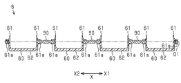
また、吸気制御弁4は、吸気制御弁本体6を備える。この吸気制御弁本体6は、X方向に並設される複数(4つ)の弁体60を有する。
各弁体60は、保持部材5の壁部51に対向する一対の側壁部61及びそれら両側壁部61の先端同士をX方向に接続する平板状の弁部62を一体的に有する。なお、この弁部62は、その一部を切り欠くことで制御通路部62aを形成する。
The intake control valve 4 includes an intake control valve body 6. The intake control valve main body 6 has a plurality (four) of
Each
各弁体60の両側壁部61には、互いに相反するX方向に略ボス状の軸部61aが突設されている。そして、各軸部61aは、X方向に開口する略鍵穴状の軸受部材52に挿通されている。この軸受部材52は、保持部材5の支持溝51aに嵌め込まれることで、保持部材5と協働して軸部61aを軸支する。つまり、各弁体60は、保持部材5及び軸受部材52を介してX方向に沿って延びる軸線周りに回動可能となっている。
On both
図2に示すように、吸気制御弁本体6は、各隣り合う弁体60同士をX方向に接続する複数(3つ)の金属製の接続軸90を有する。すなわち、接続軸90は、その両端において隣り合う弁体60の軸部61aに固着されている。従って、全ての弁体60は、一体でX方向に沿って延びる軸線(以下、「回動軸芯O1」という)の周りに回動する。
As shown in FIG. 2, the intake control valve main body 6 has a plurality (three) of
ここで、弁部62が開口5aを開放するようにその内壁面に沿って倒れる回動姿勢にあるときに、弁体60は、開口5aの開口面積を最大にする開放状態にある。一方、弁部62が開口5aの一部を閉塞するようにその内壁面から立ち上がる回動姿勢にあるときに、弁体60は、開口5aの開口面積を最小にする抑制状態にある。
Here, when the
図1に示すように、インテークマニホールド3のX1側の出口近傍には、第1取り付け部34が形成されており、該第1取り付け部34には、電動アクチュエータ7が取着されている。
As shown in FIG. 1, a
電動アクチュエータ7は、モータ71と、駆動ギア72と、金属製の回動軸73とを備える。駆動ギア72は、モータ71に駆動連結されており、回動軸芯O1を中心に回動する。回動軸73は、回動軸芯O1と同芯の略円柱形状を呈しており、X1側の端部において駆動ギア72と一体回動するように連結されている。そして、回動軸73のX2側の端部は、第1取り付け部34を貫通して隣接する弁体60と、すなわち吸気制御弁本体6と一体回動するように接続されている。つまり、回動軸73及び吸気制御弁本体6は、回動軸芯O1を中心に駆動ギア72が回動することで一体で回動するようになっている。
The
ここで、駆動ギア72及びインテークマニホールド3の間には、それらの位相が所定の初期位相(例えば弁体60の開放状態に相当する位相)に到達することで駆動ギア72の回動を規制するメカロック部(図示略)が介設されている。なお、回動軸73は、第1取り付け部34との間に介装される円環状のシール部材79に挿通されている。このシール部材79は、第1取り付け部34と回動軸73との間から、吸気通路31内の気体が外部に漏洩することを抑制するためのものである。
Here, between the
一方、インテークマニホールド3のX2側の出口近傍には、第2取り付け部35が形成されており、該第2取り付け部35には、センサユニット8が取着されている。
センサユニット8は、金属製の回動軸81を備える。回動軸81は、回動軸73と同様に回動軸芯O1と同芯の略円柱形状を呈しており、そのX1側の端部は、第2取り付け部35を貫通して隣接する弁体60と、すなわち吸気制御弁本体6と一体回動するように接続されている。つまり、回動軸81は、回動軸芯O1を中心に吸気制御弁本体6が回動することで一体で回動するようになっている。センサユニット8は、回動軸81の回動位置、すなわち吸気制御弁本体6の開度情報を検出するように構成されている。なお、回動軸73と同様に、回動軸81は、第2取り付け部35との間に介装される円環状のシール部材89に挿通されている。
On the other hand, a
The sensor unit 8 includes a
これらにより、吸気装置1には、回動軸芯O1を中心に両回動軸73、81及び吸気制御弁本体6が一体的に回動するように設けられる。なお、電動アクチュエータ7は、電子制御装置(図示略)により駆動制御されている。電子制御装置は、エンジンの回転速度と負荷の状況に基き作動マップから取り出した情報に基づいて、吸気制御弁本体6の姿勢を制御すべく電動アクチュエータ7を駆動制御する。この際、電子制御装置は、センサユニット8により検出される吸気制御弁本体6の開度情報に基づいて、電動アクチュエータ7の駆動をフィードバック制御する。
Thus, the intake device 1 is provided with the
次に、接続軸90及びこれに隣り合う弁体60の接続構造について説明する。なお、弁体60の両側壁部61、弁部62、及び軸部61aは、樹脂材にて一体的に形成されている。
Next, the connection structure of the
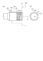
図3(a)、(b)に示すように、弁体60の接続軸90に対向する側壁部61の軸部61aは、接続軸90と接続する。この軸部61aは、回動軸芯O1と同芯で略円形の外周面61bを有する。
As shown in FIGS. 3A and 3B, the
接続軸90は、回動軸芯O1と同芯の段付き略円柱形状を呈しており、例えばインサート成形によりその両先端部91が軸部61aに埋設される。そして、接続軸90の先端部91は、その全長に亘って軸部61aの内壁面61cに密着する。先端部91は埋設部を構成する。
The connecting
各先端部91は、回動軸芯O1と同芯の略円柱状の小径部92及びその側壁部61(弁体60)側の先端92aに接続され小径部92よりも拡径される略円柱状の大径部93を有する。そして、回動軸芯O1の方向における小径部92及び大径部93の間には、移動規制部としてのテーパ状の段部95が形成される。なお、接続軸90の両先端部91間に挟まれる中間部は、軸部61aの樹脂の見切り部分となる端面61dから露出する。
Each
図4(a)、(b)に併せ示すように、大径部93の外周面93aには、回動規制部としての凹凸部94が形成される。この凹凸部94は、回動軸芯O1を中心とする径方向に等角度ごと(周期的)に凹凸する。この凹凸部94の凹凸高さ(深さ)は、回動軸芯O1を中心とする周方向の全長に亘って略一定に設定されている。また、この凹凸部94は、回動軸芯O1に沿って大径部93の全長に亘って略一定断面の形状で延びている。つまり、凹凸部94は、いわゆる平目ローレットの形状を呈する。
As shown in FIGS. 4A and 4B, an
これらにより、先端部91は、凹凸部94及び段部95において軸部61aに噛み合っている。
次に、本実施形態の作用とともに、その効果について説明する。
As a result, the
Next, the effect of this embodiment will be described.
(1)本実施形態では、接続軸90が軸部61a(弁体60)に埋設される先端部91の凹凸部94及び段部95により、弁体60に対する接続軸90の回動及び回動軸芯O1の方向への位置ずれを抑制することができる。
(1) In the present embodiment, the connecting
(2)本実施形態では、回動軸芯O1を中心に径方向に等角度毎(周期的)に凹凸する凹凸部94に合わせた先端部91と樹脂製の弁体60との噛み合いによる極めて簡易な構造で弁体60に対する接続軸90の回動を規制できる。また、凹凸部94は、周期的に凹凸を繰り返すため、凹凸部94に流れ込む樹脂に発生する応力を均等化させることができ、より堅固に弁体60に対する接続軸90の回動を規制できる。
(2) In this embodiment, it is extremely possible to engage with the
(3)本実施形態では、先端部91は、回動軸芯O1の方向において小径部92及び大径部93の間に段部95を有するため、該段部95を挟んだ小径部92及び大径部93において樹脂製の弁体60と噛み合うことになる。このように、小径部92及び大径部93における先端部91(接続軸90)と樹脂製の弁体60との噛み合いによる極めて簡易な構造で、接続軸90及び弁体60の回動軸芯O1の方向への位置ずれを規制できる。
(3) In the present embodiment, the
(4)本実施形態では、凹凸部94は、大径部93の全長に亘って回動軸芯O1の方向に沿って延びることで、弁体60及び凹凸部94(先端部91)の接触面積を増加することができる。そして、接触面積が増加する分、弁体60対する接続軸90の回動をより堅固に規制できる。
(4) In this embodiment, the
(5)金属製の接続軸と樹脂製の弁体(軸部)を圧入等により接続すると、軸部の外周面が変形することで、弁体の回動時における摺動抵抗が増加する可能性があった。これに対し、本実施形態では、軸部61aは、先端部91(凹凸部94及び段部95)を埋設した状態で樹脂製の弁体60と一体的に設けられるため、インサート成形により接続軸90と接続しつつ略円形の外周面61bが成形される。つまり、接続軸90及び弁体60の接続工程の完了時点で外周面61bの形状が決まる。従って、弁体60の回動軸における摺動抵抗の増加を抑制することができる。
(5) When a metal connecting shaft and a resin valve body (shaft part) are connected by press-fitting or the like, the outer peripheral surface of the shaft part is deformed, so that the sliding resistance during rotation of the valve body can be increased. There was sex. On the other hand, in the present embodiment, the
(6)本実施形態では、軸部61a(弁体60)の素材である樹脂が凹凸部94に流れ込むことにより、軸部61a及び先端部91の接触面積が増加することで、弁体60の捩れ剛性をより増加できる。
(6) In this embodiment, when the resin which is the raw material of the
(7)本実施形態では、弁体60に対する接続軸90の回動を規制できることで、例えば複数の気筒間で弁体60の回動位置(開度)がずれることを抑制できる。そして、当該ずれに起因する圧力損出の増加や気流の制御性能の低下を抑制できる。
(7) In the present embodiment, the rotation of the
(8)本実施形態では、弁体60に対する接続軸90の回動軸芯O1の方向への位置ずれを規制できることで、例えば弁体60及び保持部材5間の当該方向におけるクリアランスの減少又は消失を抑制できる。そして、弁体60の回動時における摺動抵抗の増加を抑制できる。
(8) In the present embodiment, the displacement in the direction of the rotation axis O1 of the
(第2の実施形態)
以下、気流制御弁構造の第2の実施形態について説明する。なお、第2の実施形態は、第1の実施形態の接続軸及び弁体の接続構造を変更した構成であるため、同様の部分についてはその詳細な説明は省略する。第2の実施形態の構成のうち第1の実施形態と同様の機能を有する構成については、十の位以降の符号を第1の実施形態と同一にしている。
(Second Embodiment)
Hereinafter, a second embodiment of the airflow control valve structure will be described. In addition, since 2nd Embodiment is the structure which changed the connection structure of the connection shaft and valve body of 1st Embodiment, the detailed description is abbreviate | omitted about the same part. Regarding the configuration having the same function as the first embodiment in the configuration of the second embodiment, the reference numerals after the tens place are the same as those of the first embodiment.
図5に示すように、軸部161aの内壁面161cにその全長に亘って密着する接続軸190の先端部191は、回動軸芯O1と同芯の略円柱状の第1軸196及びその側壁部161(弁体160)側の先端に接続された略円柱状の第2軸197を有する。第1軸196及び第2軸197の外径は互いに同等に設定されている。そして、回動軸芯O1の方向における第1軸196及び第2軸197の間には、回動軸芯O1に向かって径方向に凹む移動規制部としての略円環状の周溝199が形成される。なお、接続軸190の両先端部191間に挟まれる中間部は、軸部161aの樹脂の見切り部分となる端面161dから露出する。
As shown in FIG. 5, the
図6(a)、(b)に示すように、第2軸197の外周面197aには、回動規制部及び移動規制部としての格子状(アヤメ状、クロス状、ダイヤ状ともいう)に刻設された格子凹部198が形成される。この格子凹部198は、外周面197aの周方向を展開した状態で回動軸芯O1と平行な方向に対して第1の所定角度をなす複数の溝と、同じく第1の所定角度とは異なる第2の所定角度をなす複数の溝とが互いに交差することでなる(いわゆるアヤメローレット)。
As shown in FIGS. 6A and 6B, the outer
これらにより、先端部191は、格子凹部198及び周溝199において軸部161aに噛み合っている。
以上詳述したように、本実施形態によれば、前記第1の実施形態における(1)、(5)〜(8)の効果と同様の効果に加えて以下に示す効果が得られるようになる。
As a result, the
As described above in detail, according to this embodiment, in addition to the same effects as the effects (1) and (5) to (8) in the first embodiment, the following effects can be obtained. Become.
(1)前記第1の実施形態の接続軸90の先端部91は、移動規制部としての段部95を形成するために小径部92よりも拡径された大径部93を有した。これに対し、本実施形態では、接続軸190の先端部191に、回動規制部及び移動規制部としての格子凹部198を形成したことで、第1軸196及び第2軸197の外径を互いに同等にできる。
(1) The
(第3の実施形態)
以下、気流制御弁構造の第3の実施形態について説明する。なお、第3の実施形態は、第1の実施形態の接続軸及び弁体の接続構造を変更した構成であるため、同様の部分についてはその詳細な説明は省略する。第2の実施形態の構成のうち第1の実施形態と同様の機能を有する構成については、十の位以降の符号を第1の実施形態と同一にしている。
(Third embodiment)
Hereinafter, a third embodiment of the airflow control valve structure will be described. In addition, since 3rd Embodiment is the structure which changed the connection structure of the connection shaft and valve body of 1st Embodiment, the detailed description is abbreviate | omitted about the same part. Regarding the configuration having the same function as the first embodiment in the configuration of the second embodiment, the reference numerals after the tens place are the same as those of the first embodiment.
図7(a)、(b)に示すように、軸部261aの内壁面にその全長に亘って密着する接続軸290の先端部291は、回動軸芯O1と同芯の略円柱状の第1軸296及びその側壁部261(弁体260)側の先端に接続された略雄ねじ状の第2軸297を有する。第1軸296の外径及び第2軸297の外径(山径)は互いに同等に設定されている。なお、接続軸290の両先端部291間に挟まれる中間部は、軸部261aの樹脂の見切り部分となる端面261dから露出する。
As shown in FIGS. 7A and 7B, the
第2軸297の外周面297aは、回動規制部及び移動規制部としての螺旋状(スパイライル状)に延びるとともに回動軸芯O1を中心に径方向に凹凸する螺旋凹凸部294を形成する。これにより、先端部291は、螺旋凹凸部294において軸部261aに噛み合っている。
The outer
以上詳述したように、本実施形態によれば、前記第1の実施形態における(1)、(5)〜(8)の効果及び前記第2の実施形態における(1)の効果と同様の効果が得られるようになる。 As described in detail above, according to the present embodiment, the same effects as the effects (1), (5) to (8) in the first embodiment and the effect (1) in the second embodiment are the same. An effect comes to be acquired.
なお、上記実施形態は以下のように変更してもよい。
・前記第1の実施形態において、凹凸部94は大径部93の全長に亘って形成しなくてもよい。
In addition, you may change the said embodiment as follows.
-In the said 1st Embodiment, the uneven | corrugated |
・前記第1の実施形態において、凹凸部94の凹凸は、少なくとも1つあればよい。
・前記第1の実施形態において、段部95はテーパ状に形成しなくてもよい。すなわち、回動軸芯O1に対し直交する方向に起立するステップ状に形成してもよい。
-In the said 1st Embodiment, the unevenness | corrugation of the uneven | corrugated |
In the first embodiment, the
・前記第1の実施形態において、段部95に代えて回動軸芯O1を中心に径方向に突出するフランジにしてもよい。
・前記第1の実施形態において、小径部92及び大径部93に代えて、弁体60から離間する方向に徐々に縮径する円錐台状の先端部にしてもよい。この場合、円錐台状の先端部の外周面に凹凸部(94)を形成すればよい。
In the first embodiment, instead of the
In the first embodiment, instead of the small-
・前記第1の実施形態において、回動軸芯O1の方向において、大径部93の途中に周溝を形成してもよい。
・前記第1の実施形態において、凹凸部94は等角度毎に凹凸しなくてもよい。すなわち、間欠的、非周期的に凹凸する凹凸部であってもよい。あるいは、凹凸部94に代えて、楕円形や略多角形の外壁面にしてもよい。また、先端部の外壁面に回動軸芯と平行に形成された平面を形成してもよい。
In the first embodiment, a circumferential groove may be formed in the middle of the
-In the said 1st Embodiment, the uneven | corrugated |
・前記第2の実施形態において、格子凹部198を形成する互いに交差する両溝の各々は、少なくとも1つあればよい。
・前記第2の実施形態において、格子凹部198に代えて、回動軸芯O1を中心に径方向に突出する格子凸部を形成してもよい。
In the second embodiment, at least one of the two grooves that intersect with each other to form the
In the second embodiment, instead of the lattice
・前記第2の実施形態において、周溝199は、第1軸196、296及び第2軸197の回動軸芯O1に沿う方向における任意の位置に形成してもよい。
・前記第2の実施形態において、周溝199に代えて、回動軸芯O1を中心に径方向に突出するフランジを形成してもよい。
In the second embodiment, the
In the second embodiment, instead of the
・前記第2の実施形態において、周溝199を省略してもよい。
・前記第3の実施形態において、螺旋凹凸部294の巻き数は、1以上であればよい。
・前記第2及び第3の実施形態において、第1軸196、296及び第2軸197、297の外径は、互いに異なっていてもよく、例えば第1軸196、296の外径よりも第2軸197、297の外径の方が小さくてもよい。
In the second embodiment, the
-In the said 3rd Embodiment, the winding number of the spiral uneven | corrugated |
In the second and third embodiments, the outer diameters of the
・前記第2及び第3の実施形態において、第2軸197、297の外径を弁体160、260から離間する方向に向けて縮径するようテーパ壁面を形成してもよい。
・前記第2及び第3の実施形態において、第1軸196、296を省略してもよい。
In the second and third embodiments, tapered wall surfaces may be formed so that the outer diameters of the
In the second and third embodiments, the
・前記第1〜第3の実施形態において、接続軸90、190、290及び弁体60、160、260の接続構造を回動軸73、81及び弁体60の接続構造に適用してもよい。
・前記第1〜第3の実施形態において、弁体60による気体の流れの制御としては、気筒内の縦渦(タンブル流)の制御であってもよいし、旋回流(スワール流)の制御であってもよい。
In the first to third embodiments, the connection structure of the
-In the said 1st-3rd embodiment, as control of the gas flow by the
4…吸気制御弁(気流制御弁構造)、31…吸気通路、60,160,260…弁体、90,190,290…接続軸、91,191,291…先端部(埋設部)、92…小径部、93…大径部、94…凹凸部(回動規制部)、95…段部(移動規制部)、194…格子凹部(回動規制部、移動規制部)、294…螺旋凹凸部(回動規制部、移動規制部)、O1…回動軸芯。 4 ... Intake control valve (airflow control valve structure), 31 ... Intake passage, 60, 160, 260 ... Valve body, 90, 190, 290 ... Connection shaft, 91, 191, 291 ... Tip part (buried part), 92 ... Small diameter part, 93 ... Large diameter part, 94 ... Concave and convex part (rotation restricting part), 95 ... Step part (movement restricting part), 194 ... Grid concave part (rotation restricting part, movement restricting part), 294 ... Spiral uneven part (Rotation restriction part, movement restriction part), O1...
Claims (6)
該接続軸と一体的に回動するように前記埋設部が埋設され、吸気通路の通路断面積の一部を開閉する樹脂製の弁体と、を備え、
前記埋設部は、前記弁体に対する回動を規制する回動規制部及び前記回動軸芯の方向への移動を規制する移動規制部を有する、気流制御弁構造。 A connecting shaft made of metal that has an embedded portion and rotates around a rotation axis;
The embedded portion is embedded so as to rotate integrally with the connection shaft, and includes a resin valve body that opens and closes a part of the passage cross-sectional area of the intake passage,
The embedded portion has an airflow control valve structure having a rotation restricting portion that restricts rotation with respect to the valve body and a movement restricting portion that restricts movement in the direction of the rotation axis.
前記回動規制部は、前記回動軸芯を中心に径方向に凹凸する凹凸部を有した、気流制御弁構造。 In the airflow control valve structure according to claim 1,
The said rotation control part is an airflow control valve structure which has the uneven | corrugated | grooved part which uneven | corrugates to radial direction centering | focusing on the said rotation axis.
前記埋設部は、前記回動軸芯の方向に中心線の延びる、小径部及び該小径部の前記弁体側の先端に接続され前記小径部よりも拡径された大径部を有し、
前記移動規制部は、前記小径部及び前記大径部の間に形成された段部を有する、気流制御弁構造。 In the airflow control valve structure according to claim 2,
The buried portion has a small diameter portion that extends in the direction of the rotation axis, a small diameter portion, and a large diameter portion that is connected to the tip of the small diameter portion on the valve body side and is larger in diameter than the small diameter portion,
The movement restricting portion has an air flow control valve structure having a step portion formed between the small diameter portion and the large diameter portion.
前記凹凸部は、前記大径部の全長に亘って前記回動軸芯の方向に沿って延びるように形成された、気流制御弁構造。 In the airflow control valve structure according to claim 3,
The concavo-convex portion is an airflow control valve structure formed so as to extend along the direction of the pivot axis over the entire length of the large-diameter portion.
前記接続軸の外周面は、前記回動規制部及び前記移動規制部としての格子状に刻設された格子凹部を形成する、気流制御弁構造。 In the airflow control valve structure according to claim 1,
The air flow control valve structure in which an outer peripheral surface of the connection shaft forms a lattice recess carved in a lattice shape as the rotation restricting portion and the movement restricting portion.
前記埋設部の外周面は、前記回動規制部及び前記移動規制部としての螺旋状に延びるとともに前記回動軸芯を中心に径方向に凹凸する螺旋凹凸部を形成する、気流制御弁構造。 In the airflow control valve structure according to claim 1,
The air flow control valve structure, wherein an outer peripheral surface of the embedded portion extends in a spiral shape as the rotation restricting portion and the movement restricting portion and forms a spiral uneven portion that is uneven in a radial direction around the rotation axis.
Priority Applications (3)
| Application Number | Priority Date | Filing Date | Title |
|---|---|---|---|
| JP2016124974A JP2017227191A (en) | 2016-06-23 | 2016-06-23 | Airflow control valve structure |
| US16/311,021 US20200131999A1 (en) | 2016-06-23 | 2017-03-28 | Airflow control valve structure |
| PCT/JP2017/012753 WO2017221502A1 (en) | 2016-06-23 | 2017-03-28 | Airflow control valve structure |
Applications Claiming Priority (1)
| Application Number | Priority Date | Filing Date | Title |
|---|---|---|---|
| JP2016124974A JP2017227191A (en) | 2016-06-23 | 2016-06-23 | Airflow control valve structure |
Publications (1)
| Publication Number | Publication Date |
|---|---|
| JP2017227191A true JP2017227191A (en) | 2017-12-28 |
Family
ID=60784324
Family Applications (1)
| Application Number | Title | Priority Date | Filing Date |
|---|---|---|---|
| JP2016124974A Pending JP2017227191A (en) | 2016-06-23 | 2016-06-23 | Airflow control valve structure |
Country Status (3)
| Country | Link |
|---|---|
| US (1) | US20200131999A1 (en) |
| JP (1) | JP2017227191A (en) |
| WO (1) | WO2017221502A1 (en) |
Cited By (1)
| Publication number | Priority date | Publication date | Assignee | Title |
|---|---|---|---|---|
| JP2020143675A (en) * | 2019-03-04 | 2020-09-10 | 日立オートモティブシステムズ株式会社 | Control valve |
Families Citing this family (2)
| Publication number | Priority date | Publication date | Assignee | Title |
|---|---|---|---|---|
| CN110360012B (en) * | 2019-08-09 | 2024-08-09 | 马瑞利(中国)有限公司 | Electronic throttle output shaft assembly and manufacturing method |
| WO2025029512A1 (en) * | 2023-07-28 | 2025-02-06 | Rb Distribution Inc. | Engine intake manifold |
Citations (5)
| Publication number | Priority date | Publication date | Assignee | Title |
|---|---|---|---|---|
| JP2001143924A (en) * | 1999-11-15 | 2001-05-25 | Aisin Seiki Co Ltd | Electromagnet |
| JP2003083073A (en) * | 2001-09-10 | 2003-03-19 | Keihin Corp | Variable intake device |
| JP2013050170A (en) * | 2011-08-31 | 2013-03-14 | Denso Corp | Fluid control valve |
| JP2014101822A (en) * | 2012-11-21 | 2014-06-05 | Mahle Filter Systems Japan Corp | Intake control valve for internal combustion engine |
| JP2014111935A (en) * | 2012-11-01 | 2014-06-19 | Aisin Seiki Co Ltd | Intake control valve and intake system |
Family Cites Families (11)
| Publication number | Priority date | Publication date | Assignee | Title |
|---|---|---|---|---|
| US2529572A (en) * | 1946-01-15 | 1950-11-14 | Weatherhead Co | Carburetor valve |
| US5427141A (en) * | 1994-09-19 | 1995-06-27 | Fuji Oozx Inc. | Pressure fluid control valve device |
| US5522361A (en) * | 1995-09-07 | 1996-06-04 | Ford Motor Company | Throttle shaft seal for a throttle body |
| DE19918777A1 (en) * | 1999-04-24 | 2000-10-26 | Mann & Hummel Filter | Flap valve arrangement as throttles in intake channels in IC engines has power transmission shaft connecting flap valve wings, and injection-molded valve modules |
| US7011072B2 (en) * | 2004-04-13 | 2006-03-14 | Delphi Technologies, Inc. | Shaft noise damper |
| JP2007138840A (en) * | 2005-11-18 | 2007-06-07 | Denso Corp | Intake device and method of manufacturing the same |
| EP1912011B1 (en) * | 2006-10-05 | 2009-02-11 | MAGNETI MARELLI POWERTRAIN S.p.A. | Lock coupling between two mechanical components |
| JP5115821B2 (en) * | 2008-10-30 | 2013-01-09 | アイシン精機株式会社 | Intake device for internal combustion engine |
| EP2557298B1 (en) * | 2011-08-12 | 2017-11-22 | Röchling Automotive SE & Co. KG | Flap device with at least two separately produced flaps fitted together for joint motion |
| JP6281295B2 (en) * | 2014-01-27 | 2018-02-21 | アイシン精機株式会社 | Airflow control valve structure and intake device |
| JP6780371B2 (en) * | 2016-08-26 | 2020-11-04 | アイシン精機株式会社 | Intake device |
-
2016
- 2016-06-23 JP JP2016124974A patent/JP2017227191A/en active Pending
-
2017
- 2017-03-28 WO PCT/JP2017/012753 patent/WO2017221502A1/en not_active Ceased
- 2017-03-28 US US16/311,021 patent/US20200131999A1/en not_active Abandoned
Patent Citations (5)
| Publication number | Priority date | Publication date | Assignee | Title |
|---|---|---|---|---|
| JP2001143924A (en) * | 1999-11-15 | 2001-05-25 | Aisin Seiki Co Ltd | Electromagnet |
| JP2003083073A (en) * | 2001-09-10 | 2003-03-19 | Keihin Corp | Variable intake device |
| JP2013050170A (en) * | 2011-08-31 | 2013-03-14 | Denso Corp | Fluid control valve |
| JP2014111935A (en) * | 2012-11-01 | 2014-06-19 | Aisin Seiki Co Ltd | Intake control valve and intake system |
| JP2014101822A (en) * | 2012-11-21 | 2014-06-05 | Mahle Filter Systems Japan Corp | Intake control valve for internal combustion engine |
Cited By (2)
| Publication number | Priority date | Publication date | Assignee | Title |
|---|---|---|---|---|
| JP2020143675A (en) * | 2019-03-04 | 2020-09-10 | 日立オートモティブシステムズ株式会社 | Control valve |
| JP7222754B2 (en) | 2019-03-04 | 2023-02-15 | 日立Astemo株式会社 | control valve |
Also Published As
| Publication number | Publication date |
|---|---|
| WO2017221502A1 (en) | 2017-12-28 |
| US20200131999A1 (en) | 2020-04-30 |
Similar Documents
| Publication | Publication Date | Title |
|---|---|---|
| JP5200104B2 (en) | Fuel injection device with compensation element | |
| US20110186016A1 (en) | Hold-down device for a fuel injection device | |
| JP2008175064A (en) | Butterfly type valve device | |
| WO2017221502A1 (en) | Airflow control valve structure | |
| US7434558B2 (en) | Intake apparatus and intake manifold for internal combustion engine | |
| KR20140099279A (en) | Decoupling element for a fuel injection device | |
| CN106150649B (en) | Pipe connection device for connecting two pipe ends | |
| US20180149122A1 (en) | Vehicle silencer | |
| JP2019138354A5 (en) | ||
| JP6498763B2 (en) | Camshaft having at least one axially fixed sliding element | |
| JP3944953B2 (en) | Intake device and throttle body for internal combustion engine | |
| JP4407863B2 (en) | Sealing device | |
| JP2012225367A (en) | Seal member, inner cylinder member, and joining structure for cylinder member | |
| WO2010038723A1 (en) | Compound spring | |
| US20160222935A1 (en) | Holder for fastening a component to an internal combustion engine | |
| JP2005300140A5 (en) | ||
| JP6634964B2 (en) | Airflow control valve structure and intake device | |
| JP7668894B2 (en) | Method for manufacturing a deep-drawn part for an injector, as well as an injector having a deep-drawn part of this type - Patents.com | |
| WO2020214140A1 (en) | Fuel injector with radially orientable nozzle holes using splines | |
| JP2011179479A (en) | Intake valve device | |
| CN115704482A (en) | Stop subassembly and electronic expansion valve | |
| JP4842380B2 (en) | Method and injection mold for manufacturing an intake system for an internal combustion engine, made of plastic, and manufactured intake system | |
| US20200191066A1 (en) | Intake device for internal combustion engine | |
| JP6645250B2 (en) | Intake device for internal combustion engine | |
| JP5256135B2 (en) | Structure of intake valve |
Legal Events
| Date | Code | Title | Description |
|---|---|---|---|
| A621 | Written request for application examination |
Free format text: JAPANESE INTERMEDIATE CODE: A621 Effective date: 20190513 |
|
| A131 | Notification of reasons for refusal |
Free format text: JAPANESE INTERMEDIATE CODE: A131 Effective date: 20191210 |
|
| A02 | Decision of refusal |
Free format text: JAPANESE INTERMEDIATE CODE: A02 Effective date: 20200609 |