JP2017228366A - Method for producing catalyst sheet and method of producing air electrode - Google Patents
Method for producing catalyst sheet and method of producing air electrode Download PDFInfo
- Publication number
- JP2017228366A JP2017228366A JP2016121869A JP2016121869A JP2017228366A JP 2017228366 A JP2017228366 A JP 2017228366A JP 2016121869 A JP2016121869 A JP 2016121869A JP 2016121869 A JP2016121869 A JP 2016121869A JP 2017228366 A JP2017228366 A JP 2017228366A
- Authority
- JP
- Japan
- Prior art keywords
- catalyst
- sheet
- manganese
- drying
- catalyst sheet
- Prior art date
- Legal status (The legal status is an assumption and is not a legal conclusion. Google has not performed a legal analysis and makes no representation as to the accuracy of the status listed.)
- Granted
Links
Images

Landscapes
- Inert Electrodes (AREA)
- Hybrid Cells (AREA)
Abstract
Description
本発明は、電池の電極に用いられる触媒シートの製造方法、及び空気極の製造方法に関する。 The present invention relates to a method for producing a catalyst sheet used for a battery electrode and a method for producing an air electrode.
従来、空気極の酸素還元触媒として種々のものが検討されている。例えば、白金族元素や銀などの貴金属を活性炭やカーボンパウダーに析出担持させたもの、活性炭と金属転化物とを混合させたもの、さらには金属ポルフィリン等の有機金属錯体とカーボン粉末との混合物、あるいは、それらの熱処理品などが検討されている。一般に白金族元素や銀などの貴金属の触媒効果は大きいが、特に一次電池では、空気極の再生使用は困難なことから、高価な材料を使用することはコスト面も考慮すると現実的ではない。そこで、安価な触媒の一つとしてマンガン酸化物が試みられている(例えば特許文献1参照)。 Conventionally, various oxygen reduction catalysts for the air electrode have been studied. For example, precious metals such as platinum group elements and silver deposited on activated carbon or carbon powder, mixed activated carbon and metal conversion products, and a mixture of an organometallic complex such as metal porphyrin and carbon powder, Alternatively, those heat-treated products are being studied. In general, noble metals such as platinum group elements and silver have a large catalytic effect. However, in primary batteries, it is difficult to regenerate and use the air electrode. Therefore, it is not practical to use an expensive material in view of cost. Therefore, manganese oxide has been tried as one of inexpensive catalysts (for example, see Patent Document 1).
しかし、電極への触媒付与方法として、カーボンパウダーへ触媒粉末を添加した混合粉、またはカーボンパウダーに担持させた粉末を更にバインダと供に混練して電極を製造する方法の場合、粒子間の電気的な接続が破壊され、電極において重要な電気的接続が乏しくなる欠点がある。このため、電極中において、触媒表面の反応場からの電子移動が円滑でなく、電荷移動抵抗が大きくなることから、空気極の十分な性能が得にくい。
そこで、本発明の目的は、マンガン触媒を用いた構成で電子移動を円滑化可能とし、分極特性を改善し、且つ安価な触媒シート及び空気極を製造し、提供することにある。
However, as a method for applying a catalyst to an electrode, in the case of a method in which an electrode is manufactured by mixing a mixed powder obtained by adding catalyst powder to carbon powder or a powder supported on carbon powder together with a binder, There is a drawback in that the electrical connection is broken and the important electrical connection in the electrode becomes poor. For this reason, in the electrode, the electron transfer from the reaction field on the catalyst surface is not smooth, and the charge transfer resistance increases, so that it is difficult to obtain sufficient performance of the air electrode.
Accordingly, an object of the present invention is to produce and provide a catalyst sheet and an air electrode that can facilitate electron transfer with a configuration using a manganese catalyst, improve polarization characteristics, and are inexpensive.
上記目的を達成するために、本発明は、電池の電極に用いられる触媒シートの製造方法において、導電材と有機物バインダと水を混練した後、成形乾燥してシート部材を作製し、前記シート部材に、マンガン触媒前駆体の溶液を含浸、乾燥、及び熱処理する一連の工程を、一回又は複数回行って目的の触媒量を担持した触媒シートを得ることを特徴とする。 In order to achieve the above object, the present invention provides a method for producing a catalyst sheet used in a battery electrode, wherein a conductive material, an organic binder, and water are kneaded, and then molded and dried to produce a sheet member. In addition, a series of steps of impregnating, drying, and heat-treating the manganese catalyst precursor solution is performed once or a plurality of times to obtain a catalyst sheet carrying a target amount of catalyst.
上記構成において、前記シート部材は、前記導電材と二酸化マンガン粉末と前記有機物バインダとを水で混練した後、成形乾燥して作製されることを特徴とする。また、上記構成において、前記マンガン触媒前駆体の溶液として、硝酸マンガン水溶液を用いても良い。 The said structure WHEREIN: The said sheet | seat member is knead | mixed with water after the said electrically conductive material, manganese dioxide powder, and the said organic substance binder, It shape | molds and dries, It is characterized by the above-mentioned. In the above configuration, a manganese nitrate aqueous solution may be used as the solution of the manganese catalyst precursor.
また、上記構成において、前記二酸化マンガン粉末として、電解二酸化マンガンを用いても良い。また、上記構成において、前記有機物バインダとして、前記熱処理する際の温度よりも融点が高い高分子ディスパージョンを用いても良い。 In the above structure, electrolytic manganese dioxide may be used as the manganese dioxide powder. In the above structure, a polymer dispersion having a higher melting point than the temperature at which the heat treatment is performed may be used as the organic binder.
また、本発明は、空気電池に使用される空気極の製造方法において、導電材と有機物バインダと水を混練した後、成形乾燥してシート部材を作製し、前記シート部材に、マンガン触媒前駆体の溶液を含浸、乾燥、及び熱処理する一連の工程を、一回又は複数回行って目的の触媒量を担持した触媒シートを得、前記触媒シートを集電体に圧着することで得られることを特徴とする。 Further, the present invention provides a method for producing an air electrode used in an air battery, wherein a conductive member, an organic binder, and water are kneaded and then molded and dried to produce a sheet member. A series of steps of impregnating, drying, and heat-treating the solution of the catalyst is performed once or a plurality of times to obtain a catalyst sheet carrying the target amount of catalyst, and obtained by pressure-bonding the catalyst sheet to a current collector Features.
また、上記構成において、前記シート部材は、前記導電材と二酸化マンガン粉末と前記有機物バインダとを水で混練した後、成形乾燥して作製されることを特徴とする。 In the above structure, the sheet member is produced by kneading the conductive material, manganese dioxide powder, and the organic binder with water, and then molding and drying.
本発明では、導電材と有機物バインダと水を混練した後、成形乾燥してシート部材を作製し、前記シート部材に、マンガン触媒前駆体の溶液を含浸、乾燥、及び熱処理する一連の工程を、一回又は複数回行って目的の触媒量を担持した触媒シートを得るので、マンガン触媒を用いた構成で電子移動を円滑化可能とし、分極特性を改善し、且つ安価な触媒シート及び空気極を製造し易くすることができる。 In the present invention, after kneading a conductive material, an organic binder, and water, forming and drying to produce a sheet member, the sheet member is impregnated with a solution of a manganese catalyst precursor, dried, and heat-treated, Since the catalyst sheet carrying the target amount of catalyst is obtained once or multiple times, the structure using the manganese catalyst enables smooth electron transfer, improves polarization characteristics, and provides an inexpensive catalyst sheet and air electrode. It can be made easier to manufacture.
以下、本発明の一実施の形態について説明する。
本発明の実施形態に係る触媒シートは、空気電池の空気極に用いられる。
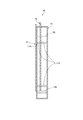
図1は空気電池の断面構造を模式的に示した図である。
空気電池10は、樹脂製のプラスチックケースで形成された外装体11を備え、この外装体11に、一対の電極を構成する空気極13と金属極15とが間隔を空けて対向配置される。この空気電池10は、外装体11内に電解液が注液されることによって、空気極13が正極として作用し、金属極15が負極として作用する一次電池である。図1中、符号ULは電解液の液面を示している。
Hereinafter, an embodiment of the present invention will be described.
The catalyst sheet which concerns on embodiment of this invention is used for the air electrode of an air battery.
FIG. 1 is a diagram schematically showing a cross-sectional structure of an air battery.
The
外装体11は、中空の箱形状に形成され、この外装体11の最も大きい面を構成する前面には、矩形の開口部11Kが設けられる。空気極13は、この開口部11Kを覆うように外装体11に装着される。また、金属極15は、外装体11の上面に形成された金属極挿入口より挿入され、外装体11の内部に形成された狭持部材11Aと支持部材11Bとによって固定される。
The
なお、外装体11を、紙を含有するシート材とし、前記シート材には、基材を構成する紙の表面にフィルムを設けたシート材を用いることも可能である。前記シート材には、熱融着性樹脂(例えば、ポリエチレン(PE))で少なくとも内面がラミネート加工された紙、つまり、ラミネート紙を用いることが可能である。
The
空気極13は、集電体と、酸素還元の触媒層を構成する触媒シートとを備え、接着などで外装体11に固定される。空気極13は、外部の空気を外装体11内に通気可能にする通気性、及び電解液を漏らさない非透液性を有している。
金属極15は、空気極13と対向するように外装体11内に支持される。この金属極15を支持する構造は、前記するように外装体11内に配置した挟持部材11Aと支持部材11Bとで固定しても良いし、また、別途形成される外装体11の蓋部で金属極15を支持するなど、様々な支持構造を適用可能である。
The
The
金属極15は、マグネシウム合金製の板材で形成され、空気極13と平行に配置される。電解液には、塩化ナトリウム水溶液が使用される。つまり、本実施形態の空気電池10はマグネシウム空気電池(金属空気電池)である。
マグネシウム空気電池は、電解液に海水を用いたり、水道水に塩を混合した液体を用いたりすることができるので、電解液の調達が容易である。なお、外装体11の内部に、電解質である塩化ナトリウムを収容した袋体を予め配置し、水道水などの水を注入するだけで発電するように構成しても良い。
The
Since the magnesium air battery can use seawater as an electrolytic solution or a liquid obtained by mixing a salt with tap water, it is easy to procure the electrolytic solution. In addition, a bag body containing sodium chloride as an electrolyte may be arranged in advance in the
この金属極15は、マグネシウム合金に限定されず、亜鉛、鉄、アルミニウムなどの金属、又はその合金を用いても良い。金属極15に亜鉛を用いた場合、電解液に水酸化カリウム水溶液を用いれば良く、金属極15に鉄を用いた場合、電解液にアルカリ系水溶液を用いれば良い。また、金属極15にアルミニウムを用いた場合、水酸化ナトリウム又は水酸化カリウムを含む電解液を用いれば良い。
The
空気極13について説明する。
空気極13の集電体は、矩形状の銅メッシュ(銅の網状体)である。なお、銅メッシュに限定されず、銅以外の金属を用いた金属メッシュなどの銅メッシュ以外の多孔構造を有する多孔質集電体を広く適用可能である。
触媒シートは、少なくとも導電材(導電性材料)とマンガン触媒とを含有するシートである。この触媒シートは、導電材と有機物バインダとを、マンガン触媒前駆体が分散する分散媒中で混練した後、成形乾燥してシート部材を作製し、シート部材に、マンガン触媒前駆体の溶液を含浸、乾燥、及び熱処理する一連の工程を、一回又は複数回行って目的の触媒量を担持したシートに作製される。この触媒シートは、所定サイズのシートに裁断された後、銅メッシュの両面に圧着して銅メッシュと一体化される。
The
The current collector of the
The catalyst sheet is a sheet containing at least a conductive material (conductive material) and a manganese catalyst. In this catalyst sheet, a conductive material and an organic binder are kneaded in a dispersion medium in which a manganese catalyst precursor is dispersed, and then molded and dried to produce a sheet member. The sheet member is impregnated with a solution of the manganese catalyst precursor. A series of steps of drying, heat treatment is performed once or a plurality of times to produce a sheet carrying the target amount of catalyst. The catalyst sheet is cut into a sheet having a predetermined size, and is then pressed onto both sides of the copper mesh to be integrated with the copper mesh.
触媒シートをシート状にする工程は、例えば、ペーストをPETフィルムに挟み、ローラープレス機を用いたプレスにより行われる。また、触媒シートを銅メッシュ(集電体)に圧着する工程は、プレス機によるプレスにより行われる。これらの工程は、公知の様々な装置を適用しても良く、例えば、圧着は、この触媒シートと銅メッシュの圧着に適した専用の圧着装置(治工具を含む)を用いて圧着しても良い。
なお、触媒シートは、後述するように、粒状の酸化還元触媒やバインダなどを練って焼成したものであるので、表面に凹凸を有しており、ローラープレス機でプレスした後もある程度の凹凸を有した状態となる。
The step of forming the catalyst sheet into a sheet is performed, for example, by pressing the paste between PET films and using a roller press. Moreover, the process of pressure-bonding the catalyst sheet to the copper mesh (current collector) is performed by pressing with a press. Various known devices may be applied to these processes. For example, the crimping may be performed using a dedicated crimping device (including jigs) suitable for crimping the catalyst sheet and the copper mesh. good.
As will be described later, since the catalyst sheet is prepared by kneading and firing a granular redox catalyst, a binder, etc., it has irregularities on the surface, and even after pressing with a roller press machine, it has some irregularities. It will have a state.
導電材は、カーボンパウダーである。より具体的には、ケッチェンブラック(KB)などのカーボンブラック、カーボンウィスカー、グラファイト、グラファイトウィスカー、活性炭、カーボンナノチューブ、カーボンナノワイヤー、カーボンナノホーンの粉末である。なお、この導電材に、銅やアルミニウムなどの金属材料、又はポリフェニレン誘導体などの有機導電性材料などのカーボン以外の導電材を用いても良い。
有機物バインダは、高分子ディスパージョンであり、具体的には、ポリテトラフルオロエチレン(PTFE、テフロン(登録商標)とも言う)などのフッ素系樹脂、又は、ポリプロピレン(PP)などのポリオレフィン系樹脂などの熱可塑性樹脂である。
The conductive material is carbon powder. More specifically, it is a powder of carbon black such as ketjen black (KB), carbon whisker, graphite, graphite whisker, activated carbon, carbon nanotube, carbon nanowire, or carbon nanohorn. In addition, you may use electrically conductive materials other than carbon, such as metal materials, such as copper and aluminum, or organic electroconductive materials, such as a polyphenylene derivative, for this electrically conductive material.
The organic binder is a polymer dispersion, specifically, a fluorine-based resin such as polytetrafluoroethylene (also referred to as PTFE or Teflon (registered trademark)), or a polyolefin-based resin such as polypropylene (PP). It is a thermoplastic resin.
分散媒は、マンガン触媒前駆体の溶液を含む。この溶液は、目的のマンガン触媒(マンガン酸化物)が得られるものであれば特に限定されない。本実施形態では、目的のマンガン触媒が二酸化マンガンであり、マンガン触媒前駆体は、硝酸マンガン(II)六水和物、又は酢酸マンガン(II)四水和物である。なお、硝酸マンガン(II)六水和物、又は酢酸マンガン(II)四水和物に代えて、他の2価のマンガン塩の水溶液を用いても良い。 The dispersion medium includes a solution of a manganese catalyst precursor. This solution is not particularly limited as long as the desired manganese catalyst (manganese oxide) can be obtained. In this embodiment, the target manganese catalyst is manganese dioxide, and the manganese catalyst precursor is manganese (II) nitrate hexahydrate or manganese acetate (II) tetrahydrate. Instead of manganese nitrate (II) hexahydrate or manganese acetate (II) tetrahydrate, other divalent manganese salt aqueous solutions may be used.
1.(実施例)
次に、実施例及び比較例を説明する。各実施例及び比較例は、触媒シートが異なる点を除いて同じ構成であり、以下、触媒シートについて説明する。各触媒シートに関する情報は表1に示している。
1. (Example)
Next, examples and comparative examples will be described. Each Example and Comparative Example have the same configuration except that the catalyst sheet is different. Hereinafter, the catalyst sheet will be described. Information on each catalyst sheet is shown in Table 1.

導電材としてKBと有機物バインダとしてPTFEと水を混練し、PTFEのフィブリル化が起こり、粘度変化が安定するまで混練を継続し、所定粘度のペーストを作製した。このペーストをPETフィルムに挟み、1mmのロールギャップに設定したローラープレス機により所定厚さのシート部材を作製した。このシート部材を80℃で2時間乾燥し、マンガン触媒を含まない触媒シートを作製した。以下、説明の便宜上、この触媒シートを、第1触媒シートと表記する。
1.1(実施例1)
第1触媒シートにエタノールを適量噴霧した後、第1触媒シートを、硝酸マンガン(II)六水和物を溶解した2M硝酸マンガン水溶液に入れ、シート中に硝酸マンガン水溶液を真空含浸した。余分な液を除去した後に、乾燥機により80℃で2時間の乾燥を行い、その後、焼成処理として、120℃の温度で2時間の熱処理を実施した。その後に、PTFEの焼結処理として、200℃で30分の熱処理を行った。
この熱処理は、大気存在下、且つ、大気圧の環境で実施した。この熱処理により、硝酸マンガン(II)の熱分解により二酸化マンガンが析出するとともに、二酸化マンガンの固定と担持とが完了する。なお、硝酸マンガンを用いる場合、焼成処理として、約120℃以上であれば二酸化マンガンを得られることを確認している。
KB as an electrically conductive material and PTFE as an organic binder and water were kneaded, and the kneading was continued until fibrillation of PTFE occurred and the viscosity change was stabilized, thereby preparing a paste having a predetermined viscosity. This paste was sandwiched between PET films, and a sheet member having a predetermined thickness was produced by a roller press set to a roll gap of 1 mm. This sheet member was dried at 80 ° C. for 2 hours to prepare a catalyst sheet containing no manganese catalyst. Hereinafter, for the convenience of explanation, this catalyst sheet is referred to as a first catalyst sheet.
1.1 (Example 1)
After an appropriate amount of ethanol was sprayed on the first catalyst sheet, the first catalyst sheet was placed in a 2M aqueous manganese nitrate solution in which manganese (II) nitrate hexahydrate was dissolved, and the aqueous manganese nitrate solution was vacuum impregnated in the sheet. After removing the excess liquid, drying was performed at 80 ° C. for 2 hours with a dryer, and then heat treatment was performed at 120 ° C. for 2 hours as a baking treatment. Thereafter, a heat treatment was performed at 200 ° C. for 30 minutes as a PTFE sintering treatment.
This heat treatment was carried out in the presence of air and in an atmospheric pressure environment. By this heat treatment, manganese dioxide is precipitated by thermal decomposition of manganese (II) nitrate, and fixation and loading of manganese dioxide are completed. In addition, when using manganese nitrate, it has confirmed that manganese dioxide can be obtained if it is about 120 degreeC or more as a baking process.
1.2(実施例2)
第1触媒シートにエタノールを適量噴霧した後、第1触媒シートを、硝酸マンガン(II)六水和物を溶解した2M硝酸マンガン水溶液に入れ、シート中に硝酸マンガン水溶液を真空含浸した。余分な液を除去した後に、乾燥機により80℃で2時間の乾燥を行い、その後、焼成処理として、120℃の温度で2時間の熱処理を実施した。さらに、焼成後の触媒シートに対し、上記の含浸、乾燥及び熱処理からなる一連の処理を、計3回実施した。その後に、PTFEの焼結処理として、200℃で30分の熱処理を行った。
なお、本実施例2、及び以下に説明する実施例3〜6及び比較例の熱処理は、実施例1と同様に、大気存在下、且つ、大気圧の環境で実施している。
1.2 (Example 2)
After an appropriate amount of ethanol was sprayed on the first catalyst sheet, the first catalyst sheet was placed in a 2M aqueous manganese nitrate solution in which manganese (II) nitrate hexahydrate was dissolved, and the aqueous manganese nitrate solution was vacuum impregnated in the sheet. After removing the excess liquid, drying was performed at 80 ° C. for 2 hours with a dryer, and then heat treatment was performed at 120 ° C. for 2 hours as a baking treatment. Furthermore, a series of treatments including the above impregnation, drying and heat treatment was performed on the catalyst sheet after firing three times in total. Thereafter, a heat treatment was performed at 200 ° C. for 30 minutes as a PTFE sintering treatment.
In addition, the heat processing of Example 2 and Examples 3 to 6 and Comparative Example described below are performed in the presence of the atmosphere and in an atmosphere of atmospheric pressure as in Example 1.
1.3(実施例3)
第1触媒シートにエタノールを適量噴霧した後、第1触媒シートを、硝酸マンガン(II)六水和物を溶解した2M硝酸マンガン水溶液に入れ、シート中に硝酸マンガン水溶液を真空含浸した。余分な液を除去した後に、乾燥機により80℃で2時間の乾燥を行い、その後、焼成処理として、120℃の温度で2時間の熱処理を実施した。さらに、焼成後の触媒シートに対し、上記の含浸、乾燥及び熱処理からなる一連の処理を、計5回実施した。その後に、PTFEの焼結処理として、200℃で30分の熱処理を行った。
つまり、実施例3は、含浸、乾燥及び熱処理からなる一連の処理を計5回実施する点が実施例2と異なる。
1.3 (Example 3)
After an appropriate amount of ethanol was sprayed on the first catalyst sheet, the first catalyst sheet was placed in a 2M aqueous manganese nitrate solution in which manganese (II) nitrate hexahydrate was dissolved, and the aqueous manganese nitrate solution was vacuum impregnated in the sheet. After removing the excess liquid, drying was performed at 80 ° C. for 2 hours with a dryer, and then heat treatment was performed at 120 ° C. for 2 hours as a baking treatment. Furthermore, a series of treatments consisting of the above impregnation, drying and heat treatment was performed on the calcined catalyst sheet 5 times in total. Thereafter, a heat treatment was performed at 200 ° C. for 30 minutes as a PTFE sintering treatment.
That is, Example 3 is different from Example 2 in that a series of treatments including impregnation, drying, and heat treatment is performed a total of five times.
1.4(実施例4)
第1触媒シートにエタノールを適量噴霧した後、第1触媒シートを、硝酸マンガン(II)六水和物を溶解した2M硝酸マンガン水溶液に入れ、シート中に硝酸マンガン水溶液を真空含浸した。余分な液を除去した後に、乾燥機により80℃で2時間の乾燥を行い、その後、焼成処理として、120℃の温度で2時間の熱処理を実施した。さらに、焼成後の触媒シートに対し、上記の含浸、乾燥及び熱処理からなる一連の処理を、計7回実施した。その後に、PTFEの焼結処理として、200℃で30分の熱処理を行った。
つまり、実施例4は、含浸、乾燥及び熱処理からなる一連の処理を計7回実施する点が実施例2と異なる。
1.4 (Example 4)
After an appropriate amount of ethanol was sprayed on the first catalyst sheet, the first catalyst sheet was placed in a 2M aqueous manganese nitrate solution in which manganese (II) nitrate hexahydrate was dissolved, and the aqueous manganese nitrate solution was vacuum impregnated in the sheet. After removing the excess liquid, drying was performed at 80 ° C. for 2 hours with a dryer, and then heat treatment was performed at 120 ° C. for 2 hours as a baking treatment. Furthermore, a series of treatments consisting of the above impregnation, drying and heat treatment were performed on the catalyst sheet after calcination a total of 7 times. Thereafter, a heat treatment was performed at 200 ° C. for 30 minutes as a PTFE sintering treatment.
That is, Example 4 is different from Example 2 in that a series of treatments including impregnation, drying, and heat treatment is performed a total of seven times.
1.5(実施例5)
有機物バインダとしてPTFEをPPに代えて第1触媒シートを作製し、この第1触媒シートを、硝酸マンガン(II)六水和物を溶解した2M硝酸マンガン水溶液に入れ、シート中に硝酸マンガン水溶液を真空含浸した。余分な液を除去した後に、乾燥機により80℃で2時間の乾燥を行い、その後、焼成処理として、120℃の温度で2時間の熱処理を実施した。さらに、焼成後の触媒シートに対し、上記の含浸、乾燥及び熱処理からなる一連の処理を、計5回実施した。その後に、PPの焼結処理として、140℃で30分の熱処理を行った。
つまり、実施例5は、有機物バインダとしてPPを用いる点、及び含浸、乾燥及び熱処理からなる一連の処理を計5回実施する点が実施例2と異なる。
なお、PPの融点が約165℃であるため、焼結処理の温度を140℃とした。
1.5 (Example 5)
A first catalyst sheet is prepared by replacing PTFE with PP as an organic binder, and the first catalyst sheet is placed in a 2M manganese nitrate aqueous solution in which manganese (II) nitrate hexahydrate is dissolved. Vacuum impregnation. After removing the excess liquid, drying was performed at 80 ° C. for 2 hours with a dryer, and then heat treatment was performed at 120 ° C. for 2 hours as a baking treatment. Furthermore, a series of treatments consisting of the above impregnation, drying and heat treatment was performed on the calcined catalyst sheet 5 times in total. Thereafter, as a PP sintering process, a heat treatment was performed at 140 ° C. for 30 minutes.
That is, Example 5 is different from Example 2 in that PP is used as the organic binder and a series of treatments including impregnation, drying, and heat treatment is performed five times in total.
Since the melting point of PP is about 165 ° C., the temperature of the sintering process was set to 140 ° C.
1.6(実施例6)
第1触媒シートにエタノールを適量噴霧した後、第1触媒シートを、酢酸マンガン(II)四水和物を溶解した2M酢酸マンガン水溶液に入れ、シート中に酢酸マンガン水溶液を真空含浸した。余分な液を除去した後に、乾燥機により80℃で2時間の乾燥を行い、その後、焼成処理として、200℃の温度で2時間の熱処理を実施した。さらに、焼成後の触媒シートに対し、上記の含浸、乾燥及び熱処理からなる一連の処理を、計5回実施した。その後に、PTFEの焼結処理として、200℃で30分の熱処理を行った。
つまり、実施例6は酢酸マンガンを使用する点が実施例3と異なる。
1.6 (Example 6)
After an appropriate amount of ethanol was sprayed onto the first catalyst sheet, the first catalyst sheet was placed in a 2M aqueous manganese acetate solution in which manganese (II) acetate tetrahydrate was dissolved, and the aqueous manganese acetate solution was vacuum impregnated into the sheet. After removing the excess liquid, drying was performed at 80 ° C. for 2 hours with a dryer, and then heat treatment was performed at 200 ° C. for 2 hours as a baking treatment. Furthermore, a series of treatments consisting of the above impregnation, drying and heat treatment was performed on the calcined catalyst sheet 5 times in total. Thereafter, a heat treatment was performed at 200 ° C. for 30 minutes as a PTFE sintering treatment.
That is, Example 6 differs from Example 3 in that manganese acetate is used.
2.(比較例)
2.1(比較例1)
第1触媒シートに対し、200℃で30分の熱処理を実施した。つまり、比較例1の触媒シートはマンガン触媒を含んでいない。
2. (Comparative example)
2.1 (Comparative Example 1)
The first catalyst sheet was heat treated at 200 ° C. for 30 minutes. That is, the catalyst sheet of Comparative Example 1 does not contain a manganese catalyst.
2.2(比較例2)
導電材としてKBと二酸化マンガン粉末とを9:1の割合とし、これに有機物バインダとしてPTFEと水を混練し、成形乾燥することにより、触媒シートを作製した。
つまり、比較例2は二酸化マンガン粉末を単純追加する方法によって、二酸化マンガンを10%含有する触媒シートとした。なお、二酸化マンガン粉末には、乾電池グレードの電解二酸化マンガン(EMD)の粉末を用いた。最終的に200℃で30分の熱処理(焼成処理)を実施した。
2.2 (Comparative Example 2)
A catalyst sheet was prepared by mixing KB and manganese dioxide powder as a conductive material at a ratio of 9: 1, kneading PTFE and water as an organic binder, and drying the mixture.
That is, Comparative Example 2 was a catalyst sheet containing 10% manganese dioxide by a method of simply adding manganese dioxide powder. As the manganese dioxide powder, dry cell grade electrolytic manganese dioxide (EMD) powder was used. Finally, heat treatment (baking treatment) was performed at 200 ° C. for 30 minutes.
2.3(比較例3)
導電材としてKBと二酸化マンガン粉末とが9:1の割合になるように、KBと、硝酸マンガン(II)六水和物を溶解した1M硝酸マンガン水溶液とを混練し、混練物を80℃で24時間乾燥した。その後、120℃で24時間の熱処理を実施し、二酸化マンガンが表面に担持された触媒粉を調製した。この触媒粉と有機物バインダとしてPTFEと水を混練して触媒シートを作製した。最終的に200℃で30分の熱処理(焼成処理)を実施した。
つまり、比較例3は、二酸化マンガンをカーボン表面に析出担持した粉末を混合し、二酸化マンガンを10%含有した触媒シートを得る点が比較例2と異なる。
2.3 (Comparative Example 3)
As a conductive material, KB and 1M manganese nitrate aqueous solution in which manganese (II) nitrate hexahydrate is dissolved are kneaded so that KB and manganese dioxide powder have a ratio of 9: 1. Dried for 24 hours. Thereafter, heat treatment was performed at 120 ° C. for 24 hours to prepare catalyst powder having manganese dioxide supported on the surface. A catalyst sheet was prepared by kneading PTFE and water as the catalyst powder and an organic binder. Finally, heat treatment (baking treatment) was performed at 200 ° C. for 30 minutes.
That is, the comparative example 3 is different from the comparative example 2 in that a powder in which manganese dioxide is deposited and supported on the carbon surface is mixed to obtain a catalyst sheet containing 10% manganese dioxide.
2.4(比較例4)
有機物バインダとしてPTFEを、バインダとしてPEに変更して触媒シート(第1触媒シートに対応するシート)を作製した。この触媒シートを、硝酸マンガン(II)六水和物を溶解した2M硝酸マンガン水溶液に入れ、シート中に硝酸マンガン水溶液を真空含浸した。余分な液を除去した後に、乾燥機により80℃で2時間の乾燥を行い、その後、焼成処理として、120℃の温度で2時間の熱処理を行った。
しかし、ポリエチレンが低融点であるため、ポリエチレンが融解して凝集し、強度が得られず、触媒シートの作製は不可能であった。なお、ポリエチレンの融点は、低密度ポリエチレンで95〜130℃である。これに対し、PTFEの融点は327℃であり、PPの融点は約165℃である。
2.4 (Comparative Example 4)
A catalyst sheet (a sheet corresponding to the first catalyst sheet) was prepared by changing PTFE as the organic binder and PE as the binder. This catalyst sheet was placed in a 2M aqueous manganese nitrate solution in which manganese (II) nitrate hexahydrate was dissolved, and the aqueous manganese nitrate solution was vacuum impregnated in the sheet. After removing the excess liquid, drying was performed at 80 ° C. for 2 hours with a dryer, and then heat treatment was performed at 120 ° C. for 2 hours as a baking treatment.
However, since polyethylene has a low melting point, the polyethylene melts and aggregates, and the strength cannot be obtained, making it impossible to produce a catalyst sheet. In addition, melting | fusing point of polyethylene is 95-130 degreeC with a low density polyethylene. On the other hand, the melting point of PTFE is 327 ° C., and the melting point of PP is about 165 ° C.
2.5(比較例5)
有機物バインダとしてPTFEを、バインダとしてPPに変更して触媒シート(第1触媒シートに対応するシート)を作製した。この触媒シートを、酢酸マンガン(II)四水和物を溶解した2M酢酸マンガン水溶液に入れ、シート中に硝酸マンガン水溶液を真空含浸した。余分な液を除去した後に、乾燥機により80℃で2時間の乾燥を行い、その後、焼成処理として、200℃で2時間の熱処理を行った。
しかし、ポリプロピレンが融解して凝集したので、強度が得られず、触媒シートの作製は不可能であった。
2.5 (Comparative Example 5)
A catalyst sheet (a sheet corresponding to the first catalyst sheet) was produced by changing PTFE as the organic binder and PP as the binder. The catalyst sheet was placed in a 2M aqueous manganese acetate solution in which manganese (II) acetate tetrahydrate was dissolved, and the aqueous manganese nitrate solution was vacuum impregnated in the sheet. After removing the excess liquid, drying was performed at 80 ° C. for 2 hours using a dryer, and then heat treatment was performed at 200 ° C. for 2 hours as a baking treatment.
However, since the polypropylene melted and aggregated, the strength was not obtained, and it was impossible to produce a catalyst sheet.
3.(評価試験)
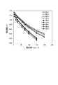
比較例4,5を除いた各触媒シートを所定サイズに切断(サイジング)し、銅メッシュの両面に圧着して空気極13を作製した。次に、各空気極13と、マグネシウム合金からなる金属極15とを用いて空気電池10をそれぞれ作製し、放電による分極試験を行った。試験結果は図2に示している。図2中、横軸は、電流密度(mA/平方センチメートル)を示し、縦軸は電池電圧(V)を示している。
3. (Evaluation test)
Each catalyst sheet except Comparative Examples 4 and 5 was cut into a predetermined size (sizing), and pressure-bonded to both sides of a copper mesh to produce an
図2に示すように、実施例1〜6は、いずれも比較例1〜3と比べて良好な特性を示した。このことは実施例1〜6が、比較例1〜3と比較して少ない触媒量で十分な効果を得ることが可能であることを示している。
また、含浸から焼成の回数が多いほど性能が更に向上する傾向が見られるが、5回と7回の差は小さく、回数は5回までが効率良く性能向上できる範囲と考えられる。
比較例については、マンガン触媒を含有しない比較例1と比べて、触媒をカーボン表面に析出担持させた比較例3と、二酸化マンガン粉末を単純追加した比較例2とが多少の分極改善は見られたが、十分な効果は得られていない。
As shown in FIG. 2, Examples 1-6 showed the favorable characteristic compared with Comparative Examples 1-3. This indicates that Examples 1 to 6 can obtain a sufficient effect with a small amount of catalyst compared to Comparative Examples 1 to 3.
Moreover, although the tendency which a performance improves further is seen, so that the frequency | count of baking from impregnation increases, the difference of 5 times and 7 times is small, and it is thought that the frequency can improve a performance efficiently up to 5 times.
As for the comparative example, compared with Comparative Example 1 containing no manganese catalyst, Comparative Example 3 in which the catalyst was deposited on the carbon surface and Comparative Example 2 in which the manganese dioxide powder was simply added showed some improvement in polarization. However, a sufficient effect has not been obtained.
本実施形態によれば、シート部材である第1触媒シート内には、導電材であるカーボンパウダーが、高分子バインダ(PTFE、PP)により固定される。そして、この第1触媒シートに、マンガン触媒前駆体の溶液を含浸、乾燥、及び熱処理する一連の工程を行うことにより、導電材及びバインダ表面にマンガン酸化物系触媒が析出形成される。この一連の工程を、一回又は複数回繰り返すことにより、十分な量の触媒がシート内部に担持される。これにより、シート内で反応場である触媒が担持されたカーボンによる導電マトリクスが形成される。従って、シート内の電子移動が容易になり、このシートと集電体とで構成された空気極13の性能が飛躍的に向上する。
According to the present embodiment, the carbon powder as the conductive material is fixed by the polymer binder (PTFE, PP) in the first catalyst sheet as the sheet member. Then, a series of steps of impregnating, drying, and heat-treating the first catalyst sheet with the solution of the manganese catalyst precursor is performed, so that a manganese oxide-based catalyst is deposited on the conductive material and the binder surface. By repeating this series of steps one or more times, a sufficient amount of catalyst is supported inside the sheet. As a result, a conductive matrix made of carbon carrying a catalyst as a reaction field in the sheet is formed. Therefore, the movement of electrons in the sheet is facilitated, and the performance of the
また、発明者等は、実施例1,2のように硝酸マンガンを用いる場合、熱処理温度として、約120℃以上であれば二酸化マンガンを得られることを確認している。実施例1,2では、触媒の析出と担持とが可能な範囲で比較的低い温度(120℃)で熱処理することにより、PTFEの分解を避けることができる。
酢酸マンガンを用いる実施例6では、120℃及び200℃で熱処理を行っている。200℃であっても、PTFEの融点(327℃)よりも十分に低いので、PTFEの分解を避けることが可能である。
上記熱処理の温度は、PTFEの分解を避ける温度であればよく、反応熱による温度上昇を考慮する観点から、320℃以下が好ましい。より好ましくは、120℃以上280℃以下が良い。なお、熱処理の時間は、バインダの種類や熱処理温度に応じて適宜に調整すれば良い。
Further, the inventors have confirmed that when using manganese nitrate as in Examples 1 and 2, manganese dioxide can be obtained if the heat treatment temperature is about 120 ° C. or higher. In Examples 1 and 2, decomposition of PTFE can be avoided by performing heat treatment at a relatively low temperature (120 ° C.) as long as the catalyst can be deposited and supported.
In Example 6 using manganese acetate, heat treatment is performed at 120 ° C. and 200 ° C. Even at 200 ° C., it is sufficiently lower than the melting point of PTFE (327 ° C.), so it is possible to avoid the decomposition of PTFE.
The temperature of the heat treatment may be any temperature that avoids the decomposition of PTFE, and is preferably 320 ° C. or lower from the viewpoint of considering a temperature rise due to reaction heat. More preferably, the temperature is 120 ° C. or higher and 280 ° C. or lower. Note that the heat treatment time may be appropriately adjusted according to the type of binder and the heat treatment temperature.
しかも、大気存在下において、大気圧で、触媒が得られる温度で熱処理するので、熱分解反応を促進させることができる。従って、安価なマンガン系触媒を効率よく作動させることができ、安価で高性能な空気電池10が得られる。特に、マンガン触媒前駆体の溶液として、硝酸マンガン水溶液を用いた場合は、化学式(式(1))のような熱分解が120℃付近で起きるので、熱処理温度を120℃以上とし、融点がこれ以上の高分子バインダである有機物バインダを用いると、シートの破壊が起こらずにマンガン酸化物系触媒を析出できる。
Mn(NO3)2→MnO2+2(NO2) ・・・式(1)
In addition, the thermal decomposition reaction can be promoted because the heat treatment is performed at atmospheric pressure and at a temperature at which the catalyst is obtained in the presence of air. Therefore, an inexpensive manganese-based catalyst can be operated efficiently, and an inexpensive and high-
Mn (NO 3 ) 2 → MnO 2 +2 (NO 2 ) (1)
マンガン触媒前駆体としては、処理温度と有機物バインダの融点との組み合わせを考慮する必要があり、例えば、硝酸マンガン(II)、酢酸マンガン(II)、又はビス酢酸マンガン(II)などを使用できる。有機物バインダは、PTFEなどのフッ素系樹脂、及びポリプロピレンなどのポリオレフィン系樹脂に限定されず、ポリイミド樹脂、又はアラミド樹脂などを使用できる。
また、有機物バインダが熱可塑性を有するので、熱処理温度がこれらの焼結温度付近のときにバインダ同士の焼結が起こり、触媒シートの機械的強度を増大させる効果も得ることができる。
As the manganese catalyst precursor, it is necessary to consider the combination of the processing temperature and the melting point of the organic binder. For example, manganese (II) nitrate, manganese (II) acetate, or manganese bis (II) acetate can be used. The organic binder is not limited to a fluorine-based resin such as PTFE and a polyolefin-based resin such as polypropylene, and a polyimide resin or an aramid resin can be used.
In addition, since the organic binder has thermoplasticity, sintering between the binders occurs when the heat treatment temperature is around these sintering temperatures, and the effect of increasing the mechanical strength of the catalyst sheet can be obtained.
このように、本実施形態の触媒シートは、導電材であるカーボンパウダーと有機物バインダと水を混練した後、成形乾燥して第1触媒シート(シート部材)を作製し、この第1触媒シートに、マンガン触媒前駆体の溶液を含浸、乾燥、及び熱処理する一連の工程を、一回又は複数回行うことによって得られる。これにより、マンガン触媒を用いた構成で電子移動を円滑化可能な触媒シートを製造し易くなる。
また、マンガン触媒前駆体の溶液を含浸、乾燥、及び熱処理する一連の工程の回数によって、触媒シートに担持される触媒量を容易に調整可能である。
Thus, the catalyst sheet of this embodiment knead | mixes the carbon powder which is a electrically conductive material, an organic substance binder, and water, Then, it shape | molds and dries and produces a 1st catalyst sheet (sheet | seat member), It is obtained by performing a series of steps of impregnating, drying, and heat-treating a solution of the manganese catalyst precursor once or a plurality of times. Thereby, it becomes easy to manufacture the catalyst sheet which can smooth an electron transfer by the structure using a manganese catalyst.
In addition, the amount of catalyst supported on the catalyst sheet can be easily adjusted by the number of series of steps of impregnating, drying, and heat-treating the manganese catalyst precursor solution.
また、触媒シートを、大気存在下において、大気圧で、触媒が得られる温度で熱処理するので、シート製造時の熱分解反応を促進させ易くなる。
また、実施例1〜5に示すように、マンガン触媒前駆体の溶液として、硝酸マンガン水溶液を用いるので、比較的低い温度でマンガン酸化物系触媒を析出形成できる。従って、融点が上記温度以上の高分子バインダである有機物バインダを選び易くなる。
さらに、有機物バインダとして、前記熱処理する際の温度よりも融点が高い高分子ディスパージョンを用いるので、有機物バインダの分解を避け、シートの破壊を回避することができる。また、この有機物バインダに熱可塑性樹脂を用いることによって、触媒シートの機械的強度を増大させることができる。
In addition, since the catalyst sheet is heat-treated at atmospheric pressure and at a temperature at which the catalyst is obtained in the presence of air, the thermal decomposition reaction during sheet production can be facilitated.
In addition, as shown in Examples 1 to 5, since an aqueous manganese nitrate solution is used as the manganese catalyst precursor solution, the manganese oxide catalyst can be deposited at a relatively low temperature. Therefore, it becomes easy to select an organic binder that is a polymer binder having a melting point equal to or higher than the above temperature.
Furthermore, since a polymer dispersion having a melting point higher than the temperature at the time of the heat treatment is used as the organic binder, decomposition of the organic binder can be avoided and destruction of the sheet can be avoided. Moreover, the mechanical strength of the catalyst sheet can be increased by using a thermoplastic resin for the organic binder.
また、上記の製造方法で製造した触媒シートを集電体に圧着することで空気極13が得られるので、マンガン触媒を用いた構成で電子移動を円滑化可能な空気極13を製造し易くなる。また、本実施形態の製造方法は、触媒シート及び空気極13に局所的な応力(例えばせん断力)を作用させずに製造可能であり、触媒シート及び空気極13の品質の安定化を図り易くなる。
Moreover, since the
続いて他の実施形態を説明する。
上述の実施形態では、第1触媒シートを、導電材であるカーボンパウダーと有機物バインダと水を混練した後、成形乾燥して作製した。これに限らず、シート部材を、導電材と二酸化マンガン粉末と有機物バインダとを分散媒中で混練した後、成形乾燥して作製しても良い。
なお、作製したシート部材に、マンガン触媒前駆体の溶液を含浸、乾燥、及び熱処理する一連の工程を、一回又は複数回行う点は、上記実施形態と同じである。
Next, another embodiment will be described.
In the above-described embodiment, the first catalyst sheet was prepared by kneading carbon powder as an electrically conductive material, an organic binder, and water, followed by molding and drying. Not limited to this, the sheet member may be produced by kneading a conductive material, manganese dioxide powder, and an organic binder in a dispersion medium, followed by molding and drying.
In addition, the point which performs the series of processes which impregnates the solution of a manganese catalyst precursor to the produced sheet member, drys, and heat-processes once or several times is the same as the said embodiment.
4.(実施例)
実施例及び比較例を説明する。各実施例及び比較例は、触媒シートが異なる点を除いて同じであり、以下、触媒シートについて説明する。各触媒シートに関する情報は表2に示している。
4). (Example)
Examples and comparative examples will be described. Each Example and Comparative Example are the same except that the catalyst sheet is different, and the catalyst sheet will be described below. Information on each catalyst sheet is shown in Table 2.
導電材としてKBと電解二酸化マンガン粉末と有機物バインダとしてPTFEと水(分散媒)とを混練し、PTFEのフィブリル化が起こり、粘度変化が安定するまで継続し、所定粘度のペーストを作製した。このペーストをPETフィルムに挟み、1mmのロールギャップに設定したローラープレス機により所定厚さのシート部材を作製した。このシート部材を270℃で30分間の乾燥及び焼成を行い、マンガン触媒を含まない触媒シート(以下、第2触媒シート)を作製した。この第2触媒シート中の組成は、電解二酸化マンガン:KB:PTFE=8:52:40とした。
ここで、電解二酸化マンガン粉末には、乾電池グレードの電解二酸化マンガン(EMD)の粉末を用いた。EMDはγ型の二酸化マンガンを主体とし、粒状である。
KB, electrolytic manganese dioxide powder as a conductive material, PTFE as an organic binder and water (dispersion medium) were kneaded, and continued until fibrillation of PTFE occurred and the viscosity change was stabilized, thereby preparing a paste having a predetermined viscosity. This paste was sandwiched between PET films, and a sheet member having a predetermined thickness was produced by a roller press set to a roll gap of 1 mm. This sheet member was dried and fired at 270 ° C. for 30 minutes to prepare a catalyst sheet containing no manganese catalyst (hereinafter referred to as “second catalyst sheet”). The composition of the second catalyst sheet was electrolytic manganese dioxide: KB: PTFE = 8: 52: 40.
Here, as the electrolytic manganese dioxide powder, dry cell grade electrolytic manganese dioxide (EMD) powder was used. EMD is mainly composed of γ-type manganese dioxide and is granular.
4.1(実施例1A)
第1触媒シートにエタノールを適量噴霧した後、第1触媒シートを、硝酸マンガン(II)六水和物を溶解した0.5M硝酸マンガン水溶液に入れ、シート中に硝酸マンガン水溶液を真空含浸した。余分な液を除去した後に、乾燥機により80℃で2時間の乾燥を行い、その後、焼成処理として、200℃の温度で1時間の熱処理を実施した。
上記の熱処理は、大気存在下、且つ、大気圧の環境で実施した。200℃は、触媒が得られる温度である。この熱処理により、硝酸マンガン(II)の熱分解により二酸化マンガンが析出するとともに、二酸化マンガンの固定と担持とが完了する。触媒シート全体重量に対し、二酸化マンガンの総添加量は10mass%である。
なお、析出する二酸化マンガンはα型とβ型とを含み、第1触媒シートはγ型の二酸化マンガンを含むので、触媒シートにはα型、β型、及びγ型の二酸化マンガンが混在する。
4.1 (Example 1A)
After an appropriate amount of ethanol was sprayed on the first catalyst sheet, the first catalyst sheet was placed in a 0.5 M aqueous manganese nitrate solution in which manganese (II) nitrate hexahydrate was dissolved, and the aqueous manganese nitrate solution was vacuum impregnated in the sheet. After removing the excess liquid, drying was performed at 80 ° C. for 2 hours with a dryer, and then heat treatment was performed at 200 ° C. for 1 hour as a baking treatment.
The above heat treatment was carried out in the presence of air and in an atmosphere of atmospheric pressure. 200 ° C. is the temperature at which the catalyst is obtained. By this heat treatment, manganese dioxide is precipitated by thermal decomposition of manganese (II) nitrate, and fixation and loading of manganese dioxide are completed. The total amount of manganese dioxide added is 10 mass% with respect to the total weight of the catalyst sheet.
The precipitated manganese dioxide contains α-type and β-type, and the first catalyst sheet contains γ-type manganese dioxide. Therefore, α-type, β-type, and γ-type manganese dioxide are mixed in the catalyst sheet.
4.2(実施例2A)
第2触媒シートにエタノールを適量噴霧した後、第2触媒シートを、硝酸マンガン(II)六水和物を溶解した0.5M硝酸マンガン水溶液に入れ、シート中に硝酸マンガン水溶液を真空含浸した。余分な液を除去した後に、乾燥機により80℃で2時間の乾燥を行い、その後、焼成処理として、200℃の温度で1時間の熱処理を実施した。さらに、焼成後の触媒シートに対し、上記の含浸、乾燥及び熱処理からなる一連の処理を、計3回実施した。触媒シート全体重量に対し、二酸化マンガンの総添加量は14mass%である。
なお、本実施例2A、及び以下に説明する実施例3A,4A及び比較例の熱処理は、実施例1Aと同様に、大気存在下、且つ、大気圧の環境で実施している。
4.2 (Example 2A)
After an appropriate amount of ethanol was sprayed on the second catalyst sheet, the second catalyst sheet was placed in a 0.5 M aqueous manganese nitrate solution in which manganese (II) nitrate hexahydrate was dissolved, and the aqueous manganese nitrate solution was vacuum impregnated in the sheet. After removing the excess liquid, drying was performed at 80 ° C. for 2 hours with a dryer, and then heat treatment was performed at 200 ° C. for 1 hour as a baking treatment. Furthermore, a series of treatments including the above impregnation, drying and heat treatment was performed on the catalyst sheet after firing three times in total. The total amount of manganese dioxide added is 14 mass% with respect to the total weight of the catalyst sheet.
The heat treatment of Example 2A, and Examples 3A and 4A and Comparative Examples described below are performed in the presence of air and in an atmosphere of atmospheric pressure, as in Example 1A.
4.3(実施例3A)
第2触媒シートにエタノールを適量噴霧した後、第2触媒シートを、硝酸マンガン(II)六水和物を溶解した0.5M硝酸マンガン水溶液に入れ、シート中に硝酸マンガン水溶液を真空含浸した。余分な液を除去した後に、乾燥機により80℃で2時間の乾燥を行い、その後、焼成処理として、200℃の温度で1時間の熱処理を実施した。さらに、焼成後の触媒シートに対し、上記の含浸、乾燥及び熱処理からなる一連の処理を、計5回実施した。触媒シート全体重量に対し、二酸化マンガンの総添加量は17mass%である。
4.3 (Example 3A)
After an appropriate amount of ethanol was sprayed on the second catalyst sheet, the second catalyst sheet was placed in a 0.5 M aqueous manganese nitrate solution in which manganese (II) nitrate hexahydrate was dissolved, and the aqueous manganese nitrate solution was vacuum impregnated in the sheet. After removing the excess liquid, drying was performed at 80 ° C. for 2 hours with a dryer, and then heat treatment was performed at 200 ° C. for 1 hour as a baking treatment. Furthermore, a series of treatments consisting of the above impregnation, drying and heat treatment was performed on the calcined catalyst sheet 5 times in total. The total amount of manganese dioxide added is 17 mass% with respect to the total weight of the catalyst sheet.
4.4(実施例4A)
第2触媒シートにエタノールを適量噴霧した後、第2触媒シートを、硝酸マンガン(II)六水和物を溶解した0.5M硝酸マンガン水溶液に入れ、シート中に硝酸マンガン水溶液を真空含浸した。余分な液を除去した後に、乾燥機により80℃で2時間の乾燥を行い、その後、焼成処理として、200℃の温度で1時間の熱処理を実施した。さらに、焼成後の触媒シートに対し、上記の含浸、乾燥及び熱処理からなる一連の処理を、計7回実施した。触媒シート全体重量に対し、二酸化マンガンの総添加量は20mass%である。
4.4 (Example 4A)
After an appropriate amount of ethanol was sprayed on the second catalyst sheet, the second catalyst sheet was placed in a 0.5 M aqueous manganese nitrate solution in which manganese (II) nitrate hexahydrate was dissolved, and the aqueous manganese nitrate solution was vacuum impregnated in the sheet. After removing the excess liquid, drying was performed at 80 ° C. for 2 hours with a dryer, and then heat treatment was performed at 200 ° C. for 1 hour as a baking treatment. Furthermore, a series of treatments consisting of the above impregnation, drying and heat treatment were performed on the catalyst sheet after calcination a total of 7 times. The total amount of manganese dioxide added is 20 mass% with respect to the total weight of the catalyst sheet.
5.(比較例)
5.1(比較例1A)
導電材としてKBと有機物バインダとしてPTFEと水を混練し、PTFEのフィブリル化が起こり、粘度変化が安定するまで継続し、所定粘度のペースト(電材料スラリー)を作製した。このペーストをPETフィルムに挟み、1mmのロールギャップに設定したローラープレス機により所定厚さのシート部材を作製した。このシート部材を200℃で1時間の乾燥及び焼成を行い、マンガン触媒を含まない触媒シートを作製した。この触媒シート中の組成は、KB:PTFE=60:40とした。
5. (Comparative example)
5.1 (Comparative Example 1A)
KB as an electrically conductive material and PTFE as an organic binder and water were kneaded, and fibrillation of PTFE occurred and continued until the viscosity change was stabilized, thereby preparing a paste (electric material slurry) having a predetermined viscosity. This paste was sandwiched between PET films, and a sheet member having a predetermined thickness was produced by a roller press set to a roll gap of 1 mm. This sheet member was dried and fired at 200 ° C. for 1 hour to prepare a catalyst sheet containing no manganese catalyst. The composition in the catalyst sheet was KB: PTFE = 60: 40.
5.2(比較例2A)
導電材としてKB、電解二酸化マンガン粉末、有機物バインダとしてPTFE及び水を混練し、PTFEのフィブリル化が起こり、粘度変化が安定するまで継続し、所定粘度のペースト(電材料スラリー)を作製した。このペーストをPETフィルムに挟み、1mmのロールギャップに設定したローラープレス機により所定厚さのシート部材を作製した。このシート部材を270度で30分間の乾燥及び焼成を行い、マンガン触媒を含まない触媒シートを作製した。この触媒シート中の組成は、電解二酸化マンガン:KB:PTFE=10:50:40とした。
5.2 (Comparative Example 2A)
KB, electrolytic manganese dioxide powder as the conductive material, PTFE and water as the organic binder were kneaded and continued until fibrillation of PTFE occurred and the viscosity change was stabilized, thereby preparing a paste (electric material slurry) with a predetermined viscosity. This paste was sandwiched between PET films, and a sheet member having a predetermined thickness was produced by a roller press set to a roll gap of 1 mm. This sheet member was dried and fired at 270 degrees for 30 minutes to prepare a catalyst sheet not containing a manganese catalyst. The composition in the catalyst sheet was electrolytic manganese dioxide: KB: PTFE = 10: 50: 40.
5.3(比較例3A)
導電材としてKB、電解二酸化マンガン粉末、有機物バインダとしてPTFE及び水を混練し、PTFEのフィブリル化が起こり、粘度変化が安定するまで継続し、所定粘度のペースト(電材料スラリー)を作製した。このペーストをPETフィルムに挟み、1mmのロールギャップに設定したローラープレス機により所定厚さのシート部材を作製した。このシート部材を270度で30分間の乾燥及び焼成を行い、マンガン触媒を含まない触媒シートを作製した。この触媒シート中の組成は、電解二酸化マンガン:KB:PTFE=30:30:40とした。
5.3 (Comparative Example 3A)
KB, electrolytic manganese dioxide powder as the conductive material, PTFE and water as the organic binder were kneaded and continued until fibrillation of PTFE occurred and the viscosity change was stabilized, thereby preparing a paste (electric material slurry) with a predetermined viscosity. This paste was sandwiched between PET films, and a sheet member having a predetermined thickness was produced by a roller press set to a roll gap of 1 mm. This sheet member was dried and fired at 270 degrees for 30 minutes to prepare a catalyst sheet not containing a manganese catalyst. The composition in the catalyst sheet was electrolytic manganese dioxide: KB: PTFE = 30: 30: 40.
5.4(比較例4A)
導電材としてKBと二酸化マンガン粉末とが5:1の割合になるように、KBと、硝酸マンガン(II)六水和物を溶解した1M硝酸マンガン水溶液とを混練し、混練物を80℃で24時間乾燥した。その後、200℃で1時間の熱処理した後、粉砕し、KBの表面に二酸化マンガン担持された触媒粉を調製した。この触媒粉と有機物バインダとしてPTFEが6:4になる比率で、触媒粉と有機物バインダとしてPTFEと水を混練して触媒シートを作製した。最終的に200℃で1時間の熱処理(焼成処理)を実施した。
このように、比較例4Aは、二酸化マンガンをカーボン表面に析出担持した粉末を混合することで、二酸化マンガンを10%含有した触媒シートを作製した。
5.4 (Comparative Example 4A)
As a conductive material, KB and a 1M manganese nitrate aqueous solution in which manganese (II) nitrate hexahydrate is dissolved are kneaded so that the ratio of KB and manganese dioxide powder is 5: 1. Dried for 24 hours. Then, after heat-processing at 200 degreeC for 1 hour, it grind | pulverized and the catalyst powder by which manganese dioxide was carry | supported on the surface of KB was prepared. A catalyst sheet was prepared by kneading PTFE and water as the catalyst powder and organic binder at a ratio of PTFE of 6: 4 as the catalyst powder and organic binder. Finally, heat treatment (baking treatment) was performed at 200 ° C. for 1 hour.
Thus, Comparative Example 4A produced a catalyst sheet containing 10% manganese dioxide by mixing the powder in which manganese dioxide was deposited and supported on the carbon surface.
6.(評価試験)
各触媒シートを所定サイズに切断(サイジング)し、集電体となる銅メッシュの両面に圧着して空気極13を作製した。また、銅メッシュの一方側に実施例1Aの触媒シート、他方側に比較例1Aの金属触媒を含まない触媒シートを圧着して空気極13を作製した。
次に、各空気極13と、マグネシウム合金からなる金属極15とを用いて空気電池10をそれぞれ作製し、放電による分極試験を行った。各空気電池10の空気極13の仕様は表3に示し、試験結果は図3に示している。
6). (Evaluation test)
Each catalyst sheet was cut into a predetermined size (sizing), and pressure-bonded to both sides of a copper mesh serving as a current collector to produce an
Next, each of the
図3に示すように、実施例1A〜4Aに係る触媒シートを使用した電池1〜4は、比較例1A〜4Aに係る触媒シートを使用した電池5〜8と比べて、良好な結果を示した。このことは実施例1A〜4Aが、比較例1A〜4Aと比較して少ない触媒量で十分な効果を得ていることを示している。
一般に、EMDは、十分な触媒活性を得るためには数十%の程度の添加が必要である。その理由は、EMDを単純追加しただけでは、各EMD粒子は独立してカーボンと接触しているだけであり、触媒表面の反応場からの電子移動が円滑ではないと考えられるからである。
これに対し、本実施例1A〜4Aでは、表2に示すように、二酸化マンガンがトータルで10%〜20%の範囲にも関わらず、十分な効果を得ている。つまり、本実施例では、EMDを使用し、且つ、二酸化マンガンの全添加量を抑えつつ、シート内の電子移動を円滑化可能であり、これにより、高性能な空気極13を得やすくなる。
As shown in FIG. 3, the batteries 1 to 4 using the catalyst sheets according to Examples 1A to 4A show better results than the batteries 5 to 8 using the catalyst sheets according to Comparative Examples 1A to 4A. It was. This has shown that Example 1A-4A has acquired sufficient effect with the small catalyst amount compared with Comparative Example 1A-4A.
In general, EMD requires an addition of several tens of percent in order to obtain sufficient catalytic activity. The reason for this is that, simply by adding EMD, each EMD particle is only in contact with carbon independently, and it is considered that the electron transfer from the reaction field on the catalyst surface is not smooth.
On the other hand, in Examples 1A to 4A, as shown in Table 2, sufficient effects are obtained regardless of the total manganese dioxide content in the range of 10% to 20%. That is, in this embodiment, EMD is used, and the electron transfer in the sheet can be facilitated while suppressing the total addition amount of manganese dioxide, which makes it easy to obtain a high-
また、含浸から焼成の回数が多いほど性能が更に向上する傾向が見られるが、3回と7回の差は小さく、回数は3回までが効率良く性能向上できる範囲と考えられる。
図3に示す電池9は、電解液側に実施例1Aの触媒シート、空気側に比較例1Aの金属触媒を含まない触媒シートを圧着した空気極13を用いている。この電池9は、実施例1Aに近い特性を得ており、比較例1A〜4Aと比べて良好な特性である。このように、空気側に触媒量が少ない触媒シートを採用することによって、より少ない触媒量で良好な特性を確保し易くなる。
Moreover, although the tendency which a performance improves further is seen, so that there are many frequency | counts of baking from an impregnation, the difference of 3 times and 7 times is small, and the frequency | count can be considered as the range which can improve a performance efficiently up to 3 times.
The battery 9 shown in FIG. 3 uses an
比較例については、マンガン触媒を含有しない比較例1と比べて、触媒をカーボン表面に析出担持させた電池8(比較例4A)と、二酸化マンガン粉末を単純追加した電池6(比較例2A)及び電池7(比較例3A)とが多少の分極低下は見られたが、十分な効果は得られていない。 As for the comparative example, compared with Comparative Example 1 containing no manganese catalyst, a battery 8 (Comparative Example 4A) in which the catalyst is deposited and supported on the carbon surface, a battery 6 (Comparative Example 2A) in which manganese dioxide powder is simply added, and The battery 7 (Comparative Example 3A) showed some decrease in polarization, but a sufficient effect was not obtained.
以上説明したように、本実施形態の触媒シートは、導電材と、有機物バインダと、分散媒である水で混練した後、成形乾燥して触媒シート(シート部材)を作製し、この触媒シートに、マンガン触媒前駆体の溶液を含浸、乾燥、及び熱処理する一連の工程を、一回又は複数回行うことによって得られる。これにより、二酸化マンガン粉末を利用しつつ、マンガン触媒を用いた構成で電子移動を円滑化可能とし、分極特性を改善し、且つ安価な触媒シートを製造し易くなる。
また、マンガン触媒前駆体の溶液を含浸、乾燥、及び熱処理する一連の工程の回数によって、触媒シートに担持される触媒量を容易に調整可能である、といった上述の各種の効果を得ることができる。
また、触媒シートは、導電材であるカーボンパウダーと有機物バインダとを水で混練した後、成形乾燥して作製されるので、有機物バインダに用いた高分子ディスパージョンにより水分の透過を抑制したシートを得ることができる。
As described above, the catalyst sheet of the present embodiment is kneaded with a conductive material, an organic binder, and water as a dispersion medium, and then molded and dried to produce a catalyst sheet (sheet member). It is obtained by performing a series of steps of impregnating, drying, and heat-treating a solution of the manganese catalyst precursor once or a plurality of times. Thereby, it is possible to facilitate the electron transfer with the structure using the manganese catalyst while using the manganese dioxide powder, to improve the polarization characteristics, and to easily manufacture an inexpensive catalyst sheet.
Further, it is possible to obtain the above-described various effects that the amount of catalyst supported on the catalyst sheet can be easily adjusted by the number of series of steps of impregnating, drying, and heat-treating the manganese catalyst precursor solution. .
In addition, the catalyst sheet is produced by kneading a carbon powder, which is a conductive material, and an organic binder with water, followed by molding and drying. Therefore, a sheet in which moisture permeation is suppressed by the polymer dispersion used in the organic binder is used. Can be obtained.
しかも、二酸化マンガン粉末に電解二酸化マンガンを用いるので、乾電池の正極活物質として使用される電解二酸化マンガン(EMD)を利用しつつ、EMDを単純添加したものと比べて、触媒シートとしての性能向上が可能である。
また、二酸化マンガン粉末の量の調整によっても、触媒シートに担持される触媒量を調整することが可能である。
In addition, since electrolytic manganese dioxide is used for the manganese dioxide powder, the performance improvement as a catalyst sheet can be achieved as compared with the case where EMD is simply added while using electrolytic manganese dioxide (EMD) used as the positive electrode active material of the dry battery. Is possible.
It is also possible to adjust the amount of catalyst supported on the catalyst sheet by adjusting the amount of manganese dioxide powder.
なお、二酸化マンガン粉末に電解二酸化マンガンを用いる場合を説明したが、これに限らず、電解二酸化マンガン以外の二酸化マンガン粉末を使用しても良い。また、分散媒に水を用いる場合を例示したが、水との混合物、或いは、水以外の分散媒を用いても良い。 In addition, although the case where electrolytic manganese dioxide was used for the manganese dioxide powder was described, the present invention is not limited thereto, and manganese dioxide powder other than electrolytic manganese dioxide may be used. Moreover, although the case where water was used for the dispersion medium was illustrated, a mixture with water or a dispersion medium other than water may be used.
また、本発明は上述の各実施形態に限定されるものではなく、本発明の技術思想に基づいて各種の変形、及び変更が可能である。例えば、上述の各触媒シートは、様々な空気電池の空気極に用いることができる。また、各触媒シートを、空気電池以外の電池の極板に用いても良い。 The present invention is not limited to the above-described embodiments, and various modifications and changes can be made based on the technical idea of the present invention. For example, each catalyst sheet described above can be used for the air electrode of various air batteries. Moreover, you may use each catalyst sheet for the electrode plates of batteries other than an air battery.
10 空気電池
11 外装体
11A 狭持部材
11B 支持部材
11K 開口部
13 空気極
15 金属極
DESCRIPTION OF
Claims (7)
導電材と有機物バインダと水を混練した後、成形乾燥してシート部材を作製し、前記シート部材に、マンガン触媒前駆体の溶液を含浸、乾燥、及び熱処理する一連の工程を、一回又は複数回行って目的の触媒量を担持した触媒シートを得ることを特徴とする触媒シートの製造方法。 In the manufacturing method of the catalyst sheet used for the electrode of the battery,
After a conductive material, an organic binder and water are kneaded, a sheet member is formed by drying, and a series of steps of impregnating, drying, and heat treating the sheet member with a solution of a manganese catalyst precursor is performed once or plural times. A method for producing a catalyst sheet, characterized in that a catalyst sheet carrying a target amount of catalyst is obtained by performing the process once.
導電材と有機物バインダと水を混練した後、成形乾燥してシート部材を作製し、前記シート部材に、マンガン触媒前駆体の溶液を含浸、乾燥、及び熱処理する一連の工程を、一回又は複数回行って目的の触媒量を担持した触媒シートを得、前記触媒シートを集電体に圧着することで得られることを特徴とする空気極の製造方法。 In the manufacturing method of the air electrode used for the air battery,
After a conductive material, an organic binder and water are kneaded, a sheet member is formed by drying, and a series of steps of impregnating, drying, and heat treating the sheet member with a solution of a manganese catalyst precursor is performed once or plural times. A method for producing an air electrode, comprising: obtaining a catalyst sheet carrying a desired amount of catalyst by performing the process once, and pressing the catalyst sheet on a current collector.
Priority Applications (1)
| Application Number | Priority Date | Filing Date | Title |
|---|---|---|---|
| JP2016121869A JP6717682B2 (en) | 2016-06-20 | 2016-06-20 | Method for producing catalyst sheet and method for producing air electrode |
Applications Claiming Priority (1)
| Application Number | Priority Date | Filing Date | Title |
|---|---|---|---|
| JP2016121869A JP6717682B2 (en) | 2016-06-20 | 2016-06-20 | Method for producing catalyst sheet and method for producing air electrode |
Publications (2)
| Publication Number | Publication Date |
|---|---|
| JP2017228366A true JP2017228366A (en) | 2017-12-28 |
| JP6717682B2 JP6717682B2 (en) | 2020-07-01 |
Family
ID=60889303
Family Applications (1)
| Application Number | Title | Priority Date | Filing Date |
|---|---|---|---|
| JP2016121869A Expired - Fee Related JP6717682B2 (en) | 2016-06-20 | 2016-06-20 | Method for producing catalyst sheet and method for producing air electrode |
Country Status (1)
| Country | Link |
|---|---|
| JP (1) | JP6717682B2 (en) |
Cited By (1)
| Publication number | Priority date | Publication date | Assignee | Title |
|---|---|---|---|---|
| CN116078432A (en) * | 2022-11-29 | 2023-05-09 | 广东宜纳新材料科技有限公司 | Monoatomic base catalyst and preparation method thereof |
-
2016
- 2016-06-20 JP JP2016121869A patent/JP6717682B2/en not_active Expired - Fee Related
Cited By (1)
| Publication number | Priority date | Publication date | Assignee | Title |
|---|---|---|---|---|
| CN116078432A (en) * | 2022-11-29 | 2023-05-09 | 广东宜纳新材料科技有限公司 | Monoatomic base catalyst and preparation method thereof |
Also Published As
| Publication number | Publication date |
|---|---|
| JP6717682B2 (en) | 2020-07-01 |
Similar Documents
| Publication | Publication Date | Title |
|---|---|---|
| JP6306028B2 (en) | Electrode assembly and method for its preparation | |
| JP5131913B2 (en) | Carbon coating method for particles used for electrode material and secondary battery | |
| JP5900144B2 (en) | Inorganic magnesium solid electrolyte, magnesium battery, and method for producing inorganic magnesium solid electrolyte | |
| CN1577660A (en) | Method for producing electrode used for electrochemical capacitor and method for producing electrochemical capacitor | |
| Li et al. | Sheet‐on‐Sheet Hierarchical Nanostructured C@ MnO2 for Zn‐Air and Zn‐MnO2 Batteries | |
| CN107302092B (en) | Current collector, battery, and methods for producing them | |
| Sarkar et al. | A cost-effective and high-performance core-shell-nanorod-based ZnO/α-Fe2O3//ZnO/C asymmetric supercapacitor | |
| JP4754790B2 (en) | Method for manufacturing battery electrode | |
| JP2010170854A (en) | Method of manufacturing positive electrode for nonaqueous electrolyte battery, positive electrode for nonaqueous electrolyte battery, and nonaqueous electrolyte battery | |
| JP2015111531A (en) | ELECTROLYTE MEMBRANE FOR SECONDARY BATTERY, JOINT, METAL-AIR ALL-SOLID SECONDARY BATTERY, AND METHOD FOR PRODUCING THE JOINT | |
| JP2015041572A (en) | Inorganic magnesium solid electrolyte, magnesium battery, electrochemical device and method for producing inorganic magnesium solid electrolyte | |
| CN107331878A (en) | Lithium manganese dioxide cell positive pole pore creating material, the porous anode using its preparation | |
| JP2011198559A (en) | Electrode manufacturing method, electrode manufacturing apparatus, and electrode | |
| KR20130116455A (en) | Active carbon-transition metal oxide for electrode active material and manufacturing method of the same | |
| JP6717682B2 (en) | Method for producing catalyst sheet and method for producing air electrode | |
| JP7703858B2 (en) | Manufacturing method for all-solid-state batteries | |
| JP2005276444A (en) | Battery electrode manufacturing method, battery electrode manufacturing apparatus, and battery electrode | |
| JP6721552B2 (en) | Lithium air secondary battery | |
| JP2012004066A (en) | Secondary battery, secondary battery electrode and method of manufacturing the same | |
| JP6717681B2 (en) | Method for producing catalyst sheet and method for producing air electrode | |
| KR101105715B1 (en) | Electrode for electric energy storage device and manufacturing method thereof | |
| CN111509194B (en) | Method for producing a cathode for a solid-state battery | |
| JP5381639B2 (en) | Solid electrolyte fuel cell and manufacturing method thereof | |
| KR101373723B1 (en) | Manufacturing method of cathode of lithium primary battery | |
| KR101383054B1 (en) | Manufacturing method of cathode of lithium primary battery |
Legal Events
| Date | Code | Title | Description |
|---|---|---|---|
| A621 | Written request for application examination |
Free format text: JAPANESE INTERMEDIATE CODE: A621 Effective date: 20181225 |
|
| A977 | Report on retrieval |
Free format text: JAPANESE INTERMEDIATE CODE: A971007 Effective date: 20191113 |
|
| A131 | Notification of reasons for refusal |
Free format text: JAPANESE INTERMEDIATE CODE: A131 Effective date: 20191126 |
|
| A521 | Request for written amendment filed |
Free format text: JAPANESE INTERMEDIATE CODE: A523 Effective date: 20200120 |
|
| TRDD | Decision of grant or rejection written | ||
| A01 | Written decision to grant a patent or to grant a registration (utility model) |
Free format text: JAPANESE INTERMEDIATE CODE: A01 Effective date: 20200526 |
|
| A61 | First payment of annual fees (during grant procedure) |
Free format text: JAPANESE INTERMEDIATE CODE: A61 Effective date: 20200611 |
|
| R150 | Certificate of patent or registration of utility model |
Ref document number: 6717682 Country of ref document: JP Free format text: JAPANESE INTERMEDIATE CODE: R150 |
|
| R250 | Receipt of annual fees |
Free format text: JAPANESE INTERMEDIATE CODE: R250 |
|
| R250 | Receipt of annual fees |
Free format text: JAPANESE INTERMEDIATE CODE: R250 |
|
| LAPS | Cancellation because of no payment of annual fees |