JP2017229181A - 充電器 - Google Patents
充電器 Download PDFInfo
- Publication number
- JP2017229181A JP2017229181A JP2016124646A JP2016124646A JP2017229181A JP 2017229181 A JP2017229181 A JP 2017229181A JP 2016124646 A JP2016124646 A JP 2016124646A JP 2016124646 A JP2016124646 A JP 2016124646A JP 2017229181 A JP2017229181 A JP 2017229181A
- Authority
- JP
- Japan
- Prior art keywords
- charger
- mounting
- attachment
- battery
- screw
- Prior art date
- Legal status (The legal status is an assumption and is not a legal conclusion. Google has not performed a legal analysis and makes no representation as to the accuracy of the status listed.)
- Granted
Links
- 210000000078 claw Anatomy 0.000 claims abstract description 51
- 230000004308 accommodation Effects 0.000 claims description 5
- 238000012986 modification Methods 0.000 description 2
- 230000004048 modification Effects 0.000 description 2
- 238000005452 bending Methods 0.000 description 1
- 230000002452 interceptive effect Effects 0.000 description 1
- 238000000034 method Methods 0.000 description 1
Images


Landscapes
- Charge And Discharge Circuits For Batteries Or The Like (AREA)
Abstract
Description
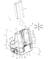
充電器は壁に取り付けられたときのバッテリの装着部は上面側に配置される。本態様の充電器は傾斜部を有する。この為、上下方向に複数の充電器を壁に固定して使用する場合、且つ、充電器間の間隔が比較的狭い場合にも、充電器にバッテリを着脱しやすい。
Claims (6)
- 壁掛け用の取付部を有する平面状の第一面と
前記第一面から立設する第二面と、
前記第二面に設けられ、電力を入出力する為のケーブルを挟持可能な鉤状の係合爪部と、
前記第一面から立設し、前記第二面と対向する第三面と、
前記第三面に設けられ、前記ケーブルを前記係合爪部に挟持していない場合に他の充電器の前記係合爪部と嵌合可能な係合凹部と、
前記第二面と前記第三面との間に設けられ、バッテリを着脱可能な装着部と、
前記第一面から立設し、前記第二面と前記第三面との間に設けられた第四面と、
前記第四面に設けられ、前記ケーブルを接続するコネクタと
を備えることを特徴とする充電器。 - 前記装着部は、前記第一面から立設し、
前記第四面と対向する第五面と、
前記第五面に設けられ、前記第四面側に凹んだ装着凹部と
を有し、
前記取付部は前記装着部を上方に配置した姿勢で、前記充電器を壁に取り付けることを特徴とする請求項1に記載の充電器。 - 前記装着部の前記第一面から離れる側の端部である第一端部から、前記第四面の前記第一面から離れる側の端部であって、前記第一端部よりも前記第一面側にある第二端部にかけて前記第一面側に傾斜する傾斜部を更に備えることを特徴とする請求項2に記載の充電器。
- 前記装着凹部は、
前記第一面側に設けられた載置面と、
前記載置面から前記第一面から離れる側に突出する端子と、
前記端子よりも前記第一面から離れる側に突出し、前記充電器に対する装着姿勢が誤った状態で前記バッテリを前記装着部に装着しようとした場合に前記バッテリに当接し、前記バッテリが前記端子と接触することを抑制するリブと
を備えることを特徴とする請求項2又は3に記載の充電器。 - 前記取付部は、
前記取付部の一端側に設けられ、壁に設けられた螺子の螺子頭を収容する螺子収容部と、
前記取付部の他端側に設けられ、前記螺子収容部に前記螺子頭を案内する案内部と
を有する取付穴であることを特徴とする請求項1から4の何れかに記載の充電器。 - 前記一端側は前記取付部の前記装着部側であり、前記他端側は前記取付部の前記第四面側であり、
前記取付部は、前記装着部から前記第四面に向かう方向に並ぶ2つの前記取付穴を有し、
前記2つの取付穴の内の前記第四面側の前記取付穴の前記螺子収容部は、前記装着部側の前記取付穴の前記螺子収容部よりも、前記装着部から前記第四面に向かう方向の長さが長いことを特徴とする請求項5に記載の充電器。
Priority Applications (1)
| Application Number | Priority Date | Filing Date | Title |
|---|---|---|---|
| JP2016124646A JP6614046B2 (ja) | 2016-06-23 | 2016-06-23 | 充電器 |
Applications Claiming Priority (1)
| Application Number | Priority Date | Filing Date | Title |
|---|---|---|---|
| JP2016124646A JP6614046B2 (ja) | 2016-06-23 | 2016-06-23 | 充電器 |
Publications (2)
| Publication Number | Publication Date |
|---|---|
| JP2017229181A true JP2017229181A (ja) | 2017-12-28 |
| JP6614046B2 JP6614046B2 (ja) | 2019-12-04 |
Family
ID=60892259
Family Applications (1)
| Application Number | Title | Priority Date | Filing Date |
|---|---|---|---|
| JP2016124646A Active JP6614046B2 (ja) | 2016-06-23 | 2016-06-23 | 充電器 |
Country Status (1)
| Country | Link |
|---|---|
| JP (1) | JP6614046B2 (ja) |
Citations (6)
| Publication number | Priority date | Publication date | Assignee | Title |
|---|---|---|---|---|
| JP2005229785A (ja) * | 2004-02-16 | 2005-08-25 | Yunitoron:Kk | ワイヤレスマイク用の充電器 |
| JP2006230055A (ja) * | 2005-02-15 | 2006-08-31 | Olympus Corp | クレードルおよびクレードルシステム |
| JP2006340449A (ja) * | 2005-05-31 | 2006-12-14 | Icom Inc | 充電器 |
| JP2009201324A (ja) * | 2008-02-25 | 2009-09-03 | Riken Keiki Co Ltd | 可搬型ガス警報器の充電器 |
| JP2010028969A (ja) * | 2008-07-17 | 2010-02-04 | Sanyo Electric Co Ltd | 充電器 |
| JP2010206881A (ja) * | 2009-02-28 | 2010-09-16 | Sanyo Electric Co Ltd | 携帯機器と充電台及びこの携帯機器と充電台に用いる位置決めケース |
-
2016
- 2016-06-23 JP JP2016124646A patent/JP6614046B2/ja active Active
Patent Citations (6)
| Publication number | Priority date | Publication date | Assignee | Title |
|---|---|---|---|---|
| JP2005229785A (ja) * | 2004-02-16 | 2005-08-25 | Yunitoron:Kk | ワイヤレスマイク用の充電器 |
| JP2006230055A (ja) * | 2005-02-15 | 2006-08-31 | Olympus Corp | クレードルおよびクレードルシステム |
| JP2006340449A (ja) * | 2005-05-31 | 2006-12-14 | Icom Inc | 充電器 |
| JP2009201324A (ja) * | 2008-02-25 | 2009-09-03 | Riken Keiki Co Ltd | 可搬型ガス警報器の充電器 |
| JP2010028969A (ja) * | 2008-07-17 | 2010-02-04 | Sanyo Electric Co Ltd | 充電器 |
| JP2010206881A (ja) * | 2009-02-28 | 2010-09-16 | Sanyo Electric Co Ltd | 携帯機器と充電台及びこの携帯機器と充電台に用いる位置決めケース |
Also Published As
| Publication number | Publication date |
|---|---|
| JP6614046B2 (ja) | 2019-12-04 |
Similar Documents
| Publication | Publication Date | Title |
|---|---|---|
| JP6749461B2 (ja) | 充電器 | |
| US10959589B2 (en) | Cleaner holder | |
| AU750285B2 (en) | Portable battery charger | |
| US11161359B2 (en) | Cradle having base portion and guide portion for detachably holding printer thereto | |
| US7751197B2 (en) | Fastening device, module mounting mechanism and information processing apparatus | |
| JP6614046B2 (ja) | 充電器 | |
| CN107113011B (zh) | 电气设备 | |
| US11502526B2 (en) | Battery charger capable of holding battery at its charging posture and retracted posture | |
| JPH08227759A (ja) | ケーブル接続器の離脱防止構造 | |
| US20140141652A1 (en) | Hand-held electronic device, battery with connector, battery lid, connector and connector disconnection preventing method | |
| CN212304807U (zh) | 移动电源及电子设备 | |
| US12170453B2 (en) | Charging stand | |
| JP2015162297A (ja) | 充電器 | |
| JP2008226609A (ja) | コネクタカバー | |
| JP3195400U (ja) | 交流直流変換器 | |
| CN211296237U (zh) | 便于充电的充电座 | |
| JP6601210B2 (ja) | 給電装置 | |
| CN223039346U (zh) | 电源设备 | |
| KR101787731B1 (ko) | 전원 연결장치 및 이를 포함하는 전자장치 | |
| JP5637567B2 (ja) | クレードル装置 | |
| CN201956477U (zh) | 一种刺破式排线插头 | |
| CN211296234U (zh) | 拆卸方便的充电槽件 | |
| JP2005268063A (ja) | コネクタ装置 | |
| CN120222528A (zh) | 电气设备 | |
| CN120207734A (zh) | 电气设备和箱 |
Legal Events
| Date | Code | Title | Description |
|---|---|---|---|
| A621 | Written request for application examination |
Free format text: JAPANESE INTERMEDIATE CODE: A621 Effective date: 20190122 |
|
| TRDD | Decision of grant or rejection written | ||
| A01 | Written decision to grant a patent or to grant a registration (utility model) |
Free format text: JAPANESE INTERMEDIATE CODE: A01 Effective date: 20191008 |
|
| A977 | Report on retrieval |
Free format text: JAPANESE INTERMEDIATE CODE: A971007 Effective date: 20191009 |
|
| A61 | First payment of annual fees (during grant procedure) |
Free format text: JAPANESE INTERMEDIATE CODE: A61 Effective date: 20191021 |
|
| R150 | Certificate of patent or registration of utility model |
Ref document number: 6614046 Country of ref document: JP Free format text: JAPANESE INTERMEDIATE CODE: R150 |