JP2018024558A - Molding bag for glass laminate - Google Patents
Molding bag for glass laminate Download PDFInfo
- Publication number
- JP2018024558A JP2018024558A JP2016157904A JP2016157904A JP2018024558A JP 2018024558 A JP2018024558 A JP 2018024558A JP 2016157904 A JP2016157904 A JP 2016157904A JP 2016157904 A JP2016157904 A JP 2016157904A JP 2018024558 A JP2018024558 A JP 2018024558A
- Authority
- JP
- Japan
- Prior art keywords
- bag
- string
- main body
- rope
- laminated glass
- Prior art date
- Legal status (The legal status is an assumption and is not a legal conclusion. Google has not performed a legal analysis and makes no representation as to the accuracy of the status listed.)
- Granted
Links
Images


Landscapes
- Joining Of Glass To Other Materials (AREA)
Abstract
【課題】さらなる鋭意研究により、成形用袋の内部に設ける紐状体をどのように配置するのかを見出し、より素早く減圧できて生産性に優れる合わせガラス用成形袋を提供する。【解決手段】閉じ操作可能な開口部Kを三方に有し、袋内部1Sを減圧する吸引部9が袋底部1tに装備されている合わせガラス用成形袋において、袋本体2,3は、複合ゴム製の本体シート4と、本体シート4の内面に設けられるフッ素樹脂製のフィルムシート5とを有してなり、袋底部1tは、本体底部23と、これを外から覆う底カバー6と、底カバー6内の底空間部25と、左右において本体底部23を貫通して底空間部25に配される紐状体とを備え、吸引部9における袋内部1Sでの開口部9aが、底空間部25に臨む構成とされている。【選択図】図5An object of the present invention is to find out how to arrange a string-like body provided inside a molding bag through further intensive research, and to provide a molding bag for laminated glass that can be decompressed more quickly and has excellent productivity. SOLUTION: A molded bag for laminated glass having openings K that can be closed on three sides and a suction part 9 for decompressing the inside 1S of the bag is equipped on the bottom 1t of the bag. The bag bottom part 1t includes a main body sheet 4 made of rubber and a film sheet 5 made of fluorine resin provided on the inner surface of the main body sheet 4, and the bag bottom part 1t includes a main body bottom part 23, a bottom cover 6 covering it from the outside, A bottom space portion 25 in the bottom cover 6 and string-like bodies that pass through the main body bottom portion 23 and are arranged in the bottom space portion 25 on the left and right. It is configured to face the space 25 . [Selection drawing] Fig. 5
Description
本発明は、自動車のフロントガラスなどを製造するのに用いられる合わせガラス用成形袋に関するものである。 The present invention relates to a laminated bag for laminated glass used for manufacturing a windshield of an automobile or the like.
自動車のフロントガラスや高層ビルの窓ガラスなどにおいては、破損しても破片が飛び散らないようにするために、ガラス板とガラス板との間にポリビニルブチラールのような熱溶融性の高分子フィルムを設け、その高分子フィルムを加熱溶融させてガラス板どうしを密着させた構造のガラス、いわゆる合わせガラスが用いられている。 For automobile windshields and high-rise building windowpanes, a hot-melt polymer film such as polyvinyl butyral is placed between the glass plates in order to prevent fragments from scattering even if they are broken. There is used a so-called laminated glass having a structure in which a polymer film is heated and melted and the glass plates are brought into close contact with each other.
合わせガラスは次のとおりの工程により作製される。即ち、2枚のガラス板の間に、ガラス板どうしを結合させる高分子フィルムを設けて介在させた後、内圧を真空近くにまで大きく減圧させることが可能な可撓性のある袋、即ち成形用袋に入れる。次に、成形用袋を、一般には100〜130℃の熱雰囲気中で10〜15分間、加熱処理するとともに、この間中、成形用袋内の空気を連続して吸引し続け、2枚のガラス板の間に含まれている微量の空気を除去する。このようにして、成形用袋の内と外とに生じた圧力差及び熱により、2枚のガラス板を袋壁で挟持して加圧加熱することにより製作される。 Laminated glass is produced by the following process. That is, a flexible bag, that is, a molding bag, capable of greatly reducing the internal pressure to near vacuum after providing a polymer film for bonding glass plates between two glass plates and interposing them. Put in. Next, the molding bag is generally heat-treated in a hot atmosphere at 100 to 130 ° C. for 10 to 15 minutes, and during this time, the air in the molding bag is continuously sucked and two sheets of glass are kept. Removes traces of air contained between the plates. In this manner, the two glass plates are sandwiched between the bag walls by the pressure difference and heat generated between the inside and the outside of the forming bag, and are heated by pressure.
合わせガラスの製作工程は、走行するラインで連続して行われる。つまり、成形用袋は、成形用袋の中に入れた未接着のガラス板の加熱、吸引、加圧工程を終えて合わせガラスを取り出した後には、その空になった成形用袋に迅速に次の未接着ガラス板を入れ、そして前記と同じ工程が繰返し行われる。このように、成形用袋を反復して効率よく用いるには、比較的時間の掛かる袋内部の減圧工程を素早く行えることが求められる。 The laminated glass manufacturing process is continuously performed on a traveling line. In other words, the molding bag is quickly put into the empty molding bag after the laminated glass is taken out after finishing the heating, suction, and pressurization steps of the unbonded glass plate placed in the molding bag. The next unbonded glass plate is placed and the same process is repeated. As described above, in order to use the forming bag repeatedly and efficiently, it is required that the pressure-reducing step inside the bag, which takes a relatively long time, can be performed quickly.
減圧を促進させる技術として、例えば、特許文献1においては、その段落0082(図8も参照)に記載されたように、脱気する空気の流れの妨げを防止する通気スペーサを設けること、及びその通気スペーサの例としてロープを設けることが示唆されている。つまり、成形用袋の内部に、通気スペーサとしてロープなどの紐状体を配置することが、減圧を素早く行うことにおいて有効であると考えられる。 As a technique for promoting the pressure reduction, for example, in Patent Document 1, as described in paragraph 0082 (see also FIG. 8), a ventilation spacer for preventing the flow of air to be deaerated is provided, and It has been suggested to provide a rope as an example of a ventilation spacer. That is, it is considered that placing a string-like body such as a rope as a ventilation spacer inside the molding bag is effective in reducing pressure quickly.
本発明の目的は、さらなる鋭意研究により、成形用袋の内部に設ける紐状体をどのように配置するのかを見出し、より素早く減圧できて生産性に優れる合わせガラス用成形袋を提供する点にある。 The purpose of the present invention is to find out how to arrange the string-like body provided inside the molding bag through further earnest research, and to provide a molded bag for laminated glass that can be decompressed more quickly and has excellent productivity. is there.
請求項1に係る発明は、一対の袋本体2,3の四方のうち一方以上が開口可能な開口部Kを有し、前記開口部Kは、これを開口した開き状態と密閉された閉じ状態とに切換え可能に構成されるとともに、一対の前記袋本体2,3によりなる袋内部1Sを減圧するための吸引部9が袋底部1tに装備されている合わせガラス用成形袋において、
前記袋本体2,3は、本体シート4の内面に合成樹脂製のフィルムシート5が重ねられているゴム製の前記本体シート4よりなり
前記袋底部1tは、前記袋本体2,3による本体底部23と、前記本体底部23をその外側から覆う折り返し形状の底カバー6と、前記底カバー6と前記本体底部23とで囲まれることにより前記底カバー6の内部に形成されている底空間部25と、を備えてなり、
前記底空間部25の長手方向に沿う底ロープ7Aと、前記本体底部23の両端部を貫通するサイド紐状体部7a,7bと、を有する紐状体7が前記底空間部25に設けられ、
前記吸引部9における前記袋内部1Sでの開口部9aが、前記底空間部25に臨む構成とされていることを特徴とする。
The invention according to claim 1 has an opening K in which one or more of the four sides of the pair of bag
The bag
A string-
The
請求項2に係る発明は、請求項1に記載の合わせガラス用成形袋において、
前記本体底部23には、前記紐状体7を貫通させるための挿通用孔27以外の空気孔26が設けられていることを特徴とする。
The invention according to
The
請求項3に係る発明は、請求項1又は2に記載の合わせガラス用成形袋において、
前記紐状体7は、前記袋内部1Sにおける前記袋底部1tに対する左右それぞれの縁に沿う一対の前記サイド紐状体部7a,7bを有する本体ロープ7Bと、前記底空間部25に配備される前記底ロープ7Aとを備えて構成され、
前記一対のサイド紐状体部7a,7bそれぞれの先端部が前記本体底部23に貫通されていることを特徴とする。
The invention according to
The string-
The tip ends of the pair of side string-
請求項4に係る発明は、請求項3に記載の合わせガラス用成形袋において、
前記本体ロープ7Bは、前記袋内部1Sにおける前記袋底部1tと反対側の縁に沿うように配置されている頂紐状体部7cにより、前記一対のサイド紐状体部7a,7bそれぞれの基端部が一連一体に連続されてなる三方ロープに構成されていることを特徴とする。
The invention according to
The
請求項5に係る発明は、請求項1〜4の何れか一項に記載の合わせガラス用成形袋において、
前記開口部9aと前記紐状体7との間に殆ど隙間がない程度で近接配備されるように、前記吸引部9と前記紐状体7とが連係配置されていることを特徴とする。
The invention according to
The
請求項1の発明によれば、袋底部における本体底部と底カバーとの間には、袋底部の辺方向に延びる帯状の底空間部が設けられて、その底空間部に紐状体が配置されている。故に、袋内部の減圧時に紐状体及びその付近による空気の通り道が確保されながらも、合わせガラスの配置スペースである袋内部、即ち、袋本体の大きさが、底空間部の分は小型化でき、その分のコストダウンも可能になる。 According to the invention of claim 1, a belt-like bottom space portion extending in the side direction of the bag bottom portion is provided between the main body bottom portion and the bottom cover at the bag bottom portion, and the string-like body is disposed in the bottom space portion. Has been. Therefore, the inside of the bag, which is the layout space for the laminated glass, that is, the size of the bag body is reduced in size for the bottom space, while the string-like body and the air passage therearound are secured when the bag is decompressed. It is possible to reduce the cost accordingly.
吸引部の袋内部での開口部が底空間部に臨むものであるから、開口部を袋内部よりも袋底側にある底空間部に臨ませるだけの短い長さの吸引部にできる利点もある。
その結果、さらなる鋭意研究及び工夫により、成形用袋の内部に設ける紐状体をどのように配置するのかを見出して、合理的な紐状体の配置状態が実現できたので、より素早く減圧できて生産性に優れる合わせガラス用成形袋を提供することができる。
Since the opening part inside the bag of the suction part faces the bottom space part, there is also an advantage that the suction part can have a short length enough to face the bottom space part on the bag bottom side from the inside of the bag.
As a result, through further diligent research and ingenuity, we found out how to arrange the string-like body provided inside the molding bag and realized a reasonable arrangement state of the string-like body, so that the pressure can be reduced more quickly. Thus, a molded bag for laminated glass having excellent productivity can be provided.
請求項2の発明によれば、本体底部には、複数の挿通用孔だけでなく、その他に空気孔も形成されているから、開口部からの吸引作用における袋内部での空気の流れの妨げが生じない又は生じ難いようになり、袋内部の空気を、底空間部を通して円滑に減圧することができる。
According to the invention of
請求項3の発明によれば、紐状体は、吸引部のある袋底部に配置されている底ロープと、袋本体における左右それぞれの縁に配置されている一対のサイド紐状体部との三方に設けられており、かつ、各サイド紐状体部は本体底部を貫通して底空間部に達しているから、吸引部を用いての減圧時には、袋としての四方のうちの吸引部に近い三方から袋内部の空気を効率よく、かつ、極力残さず吸い出すことが可能になる。そして、その効率の良い空気の吸出しにより、減圧に要する時間を従来品に比べて短縮化が可能となる利点もある。
According to the invention of
請求項4の発明によれば、本体ロープは、袋としての四方に紐状体が配置されており、かつ、各サイド紐状体部と頂紐状体部とが一連一体に連続されているから、請求項3の発明による前記効果がより強化される利点がある。
According to the invention of
請求項5の発明によれば、開口部と紐状体とが近接配備されているから、袋内部の減圧時には、紐状体周りの空気の通り道の空気を吸引部から効率よく吸い出すことが可能であり、より良好な減圧が行える利点がある。
According to the invention of
以下に、本発明による合わせガラス用成形袋の実施の形態を、自動車のフロントガラスなどの製造に用いられるものとして、図面を参照しながら説明する。 Hereinafter, an embodiment of a molded bag for laminated glass according to the present invention will be described with reference to the drawings as being used for manufacturing a windshield of an automobile.
〔実施例1〕
合わせガラス成形用袋(以下「成形用袋」と略称する)1は、図1,図2に示されるように、互いの根元側長辺部である袋底部1tのみが一体化された一対の袋本体2,3により構成されており、各袋本体2,3それぞれの先端側長辺部と両短辺部のほぼ全域が、即ち、三方が開閉可能に開口されている。
成形用袋1は、先端側長辺部となる先端開口部Ks、根元側の端部以外が開口されていて両短辺部となる一側及び他側開口部Ki,Ktを有している。つまり、成形用袋1は、四方のうち一方以上が開口された開口部K(Ki,Ks,Kt)を有し、開口部Kを開口した開き状態と密閉された閉じ状態とに切換え可能に構成されている。
[Example 1]
As shown in FIGS. 1 and 2, a laminated glass forming bag (hereinafter abbreviated as “molding bag”) 1 is a pair of bags in which only the
The forming bag 1 has a front end opening Ks that is a front side long side part, and one side and other side openings Ki and Kt that are open except the end part on the base side and that are both short side parts. . That is, the molding bag 1 has an opening K (Ki, Ks, Kt) in which one or more of the four sides are opened, and can be switched between an opened state in which the opening K is opened and a sealed closed state. It is configured.
袋本体2,3は、ポリエステル繊維布の表裏両面にエチレンプロピレンゴムを積層して、表面ゴム層と裏面ゴム層を有するEPDM積層布(エチレンプロピレンゴム積層布)による本体シート4と、本体シート4の内面側に圧着されるフッ素樹脂製のフィルムシート5とによりなる。また、これら可撓性を有する合成樹脂材製である各袋本体2,3の袋底部1tの外面は、折り返し形状の底カバー6により覆われている。
The
成形用袋1の内部には、成形用袋1としての使用時には下側となる一方の袋本体2の内面側に一体化された複数のループ状布8により、ほぼ矩形環状に位置決めされたロープ(紐状体の一例)7が配置されている。ロープ7及びロープ7とフィルムシート5との間の隙間が空気の通り道となり、吸引パイプ(吸引部の一例)9を用いての成形用袋1内の減圧が円滑に行われるように構成されている。ロープ7は、複数本の単ロープを捻ってなる捻りロープであるのが好ましい。
A rope positioned in a substantially rectangular ring is formed inside the molding bag 1 by a plurality of loop-shaped
各開口部Ki,Ks,Ktのそれぞれは、これら開口部Ki,Ks,Ktの閉じ状態における袋内の前記減圧を可能とするための気密構造が採られている。即ち、図2,図4に示されるように、開口部Kは、ゴム製の第1開口縁10を備える一方の袋本体2の第1開口縁10と、ゴム製の第2開口縁11を備える他方の袋本体3の第2開口縁11とを有してなる。
図1において、19はループ状に張り出た布製の取っ手であり、20は各袋本体2,3の外面補強帯である。
Each of the openings Ki, Ks, Kt has an airtight structure for enabling the pressure reduction in the bag when the openings Ki, Ks, Kt are closed. That is, as shown in FIG. 2 and FIG. 4, the opening K includes a
In FIG. 1, 19 is a cloth handle protruding in a loop shape, and 20 is an outer surface reinforcing band of each
第1開口縁10は、外側となる第1合わせ部10A、第1合わせ部10Aより高さが低くて内側となる第1重ね部10B、及び第1合わせ部10Aの内端と第1重ね部10Bの外端とを繋ぐ垂直壁でなる凸段差10Cを有して構成されている。
第2開口縁11は、外側となる第2合わせ部11A、第2合わせ部11Aより高さが高くて内側となる第2重ね部11B、及び第2合わせ部11Aの内端と第2重ね部11Bの外端とを繋ぐ垂直壁でなる凹段差11Cを有して構成されている。
The
The
成形用袋1の開き状態(図2を参照)は、第1合わせ部10Aと第2合わせ部11Aとが互いに離間した状態によりなる。このとき、第1重ね部10Bと第2重ね部11B、及び凸段差10Cと凹段差11Cとの双方も離間している。
成形用袋1の閉じ状態(図1を参照)は、第1合わせ部10Aの上面である第1合わせ面10aと、第2合わせ部11Aの下面である第2合わせ面11aとが重ね合わされた状態によりなる。このとき、第1重ね部10Bと第2重ね部11B、及び凸段差10Cと凹段差11Cとの双方が重ね合わせられておれば好都合である。
The open state of the molding bag 1 (see FIG. 2) is a state in which the
In the closed state of the molding bag 1 (see FIG. 1), the
第1合わせ面10a及び第2合わせ面11aはシール面であって、重ね合わせるだけで優れた気密性が得られるべく、第1及び第2合わせ部10A,11A、即ち第1及び第2開口縁10,11を構成するゴムの材質は、EPDMが好ましいが、その他の材質(NBR、H−NBR、CR)でも良い。また、ゴム硬度は40〜70に設定されている。
The
このようなゴムの材質設定工夫により、第1合わせ面10aと第2合わせ面11aとを重ねるだけで広い面で密着した面接触状態が得られ、成形用袋1の減圧による負圧に耐える優れたシール作用、即ち優れた気密性が発揮できるようになっている。また、成形用袋1を繰返し使用しても第1及び第2開口縁10,11が変形したり型崩れしたりすることがなく、優れた耐久性も兼ね備えたものとなっている。
By such a rubber material setting device, it is possible to obtain a surface contact state in which the
図2,図4に示すように、閉じ状態にある成形用袋1の第1開口縁10と第2開口縁11とを巻き付けて覆う巻き付け片12が、3箇所の各開口部K(Ki,Ks,Kt)に装備されている。
巻き付け片12は、一方の袋本体2を第1開口縁10より外側に所定長さ延長することで形成されており、その先端部には、面ファスナ13を形成する一対のファスナ部材13A,13Bのうちの一方のファスナ部材13Aが帯状に装備されている。そして、他方の袋本体3における第2開口縁11のすぐ傍の外面側に、他方のファスナ部材13Bが帯状に装備されている。
As shown in FIGS. 2 and 4, the wrapping
The
巻き付け片12は、図2に示されるように、開き状態では一方の袋本体2の延長上に進展されており、第1開口縁10と第2開口縁11とが重ね合わされた閉じ状態としてから、巻き付け操作される。
即ち、図4(a)に示されるように、巻き付け片12を上方に持ち上げ、重ね合わされている第1開口縁10及び第2開口縁11を巻回して覆う状態となるように引っ張り、その引っ張った状態で一方のファスナ部材13Aを他方のファスナ部材13Bに重ねて面ファスナ13を機能させる。
すると、図4(b)に示されるように、閉じられた状態の開口部Kを包み覆う状態で巻き付け片12が係止固定される。
As shown in FIG. 2, the
That is, as shown in FIG. 4 (a), the winding
Then, as shown in FIG. 4B, the winding
第1開口縁10と第2開口縁11とが重ね合わされた状態、即ち、第1合わせ面10aと第2合わせ面11aとが面接触して密着された成形用袋1の閉じ状態としてから、図外の吸引ポンプを用いて吸引パイプ9から減圧する。
この減圧操作により、成形用袋1が、これに内装されている合わせガラスを加熱・加圧処理すべく大きく(例えば、真空近くまで)減圧されると、袋本体2,3に負圧による引っ張り力が作用し、第1及び第2合わせ部10A,11Aが各先端側から互いに引き剥がされんばかりに反り上がり変形(反っくり返り変形)する。
A state in which the
If the molding bag 1 is greatly decompressed (for example, close to a vacuum) to heat and pressurize the laminated glass housed therein by this decompression operation, the
巻き付け片12を強く巻き付け固定することにより、それら第1及び第2開口縁10,11の反り上がり変形を極力防止又は規制でき、安定した気密性を保つことができる。図1,図2に示されるように、巻き付け片12は、一側及び他側開口部Ki,Ktのそれぞれと先端開口部Ksとの境目である両角部21,21には形成できない。
そのため、それら角部21における第1及び第2合わせ部10A,11Aの反り上がりが懸念される場合には、強力に弾性挟持可能なクリップ22(図1の仮想線を参照)を用いて第1開口縁10と第2開口縁11とを挟むようにしても良い。
By strongly winding and fixing the winding
Therefore, when there is a concern about the warping of the first and
開口部Kを閉じ操作する際には、第2開口縁11を、その凹段差11Cを凸段差10Cに当て付けて第1開口縁10に乗せるようにすれば、第1合わせ面10aと第2合わせ面11aとが位置ずれすることない良好な面接触状態に、簡単・素早く、しかも労力少なく重ね合わせることができる。
この閉じ状態では、図4(b)に示されるように、第1重ね部10Bと第2重ね部11Bとも丁度面接触して第2のシール部となればより気密性が高められて好都合であるが、第1合わせ面10aと第2合わせ面11aとの面接触状態を確実に得るべく、閉じ状態においては、第1重ね部10Bと第2重ね部11Bとが僅かに離れる設定でも良い。
When the opening K is closed, if the
In this closed state, as shown in FIG. 4B, if the first overlapped
成形用袋1の袋底部1tについてさらに説明する。図3に示されるように、袋底部1tは、袋本体2,3による本体底部23と、本体底部23をその外側から覆う折り返し形状の底カバー6と、底カバー6と本体底部23とで囲まれることにより底カバー6の内部に形成されている底空間部25と、を備えて構成されている。底空間部25は、袋底部1tの辺方向(矢印Z方向であって、図1を参照)に延びる帯状の空間部である。なお、図3は、ロープ7を通す挿通用孔27を通る断面図として描いてある。
The
図3、図5に示されるように、本体底部23には、袋底部1tの辺方向(矢印Z方向)に並ぶ複数の孔26,27が形成されている。直線状の底ロープ7Aとコ字状の三方ロープ7Bとでなるほぼ矩形環状のロープ7のうち、底ロープ7Aは底空間部25に配置され、サイドロープ部7a,7bの先端部は、複数の孔26,27のうちの両端の挿通用孔27,27を通して底空間部25に臨んでいる。挿通用孔27以外の孔は、袋内部1Sと底空間部25とを連通させるための空気孔26である。
As shown in FIGS. 3 and 5, the
ロープ7は、底ロープ7Aと、主に袋本体2,3に配備されている三方ロープ7Bとを有して構成されている。底ロープ7Aは、底空間部25の長手方向に沿ってほぼその全長に亘る長さでもって配備されている一直線状のロープである。三方ロープ7Bは、一対の袋本体2,3によりなる袋内部1Sにおける袋底部1tに対する左右それぞれの縁に沿う一対のサイドロープ部(「サイド紐状体部」の一例)7a,7b、及び袋底部1tと反対側の縁に沿う頂ロープ部(「頂紐状体部」の一例)7cを有し、平面視で「コ」字状を呈する状態に配備されているロープである。各サイドロープ部7a,7bと頂ロープ部7cとは一連一体に連続されている。各サイドロープ部7a,7bそれぞれの先端部は、本体底部23の左及び右端部のそれぞれに形成されている挿通用孔27を通って底空間部25に達している。
The
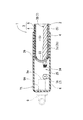
図5に示されるように、吸引パイプ9は、その袋内部1Sでの開口部9aが底空間部25に臨む状態で袋底部1tに装備されている。そして、開口部9aと紐状体7との間に殆ど隙間がない程度で近接配備されるように、吸引パイプ9と底ロープ7Aとが連係配置されている。具体的には、吸引パイプ9における袋内部1Sに位置する内側パイプ部9Aの突出長さを、底空間部25に配置されている底ロープ7Aに当接せんばかりの状態に設定することが挙げられる。
As shown in FIG. 5, the
このような構成とすれば、減圧時において、開口部9aと底ロープ7Aとの間で袋底部1tがひしゃげず(潰れず)、空気の通り道が確保されて、円滑な空気の吸引状態が得られるようになる。なお、図3,5に示されるように、底ロープ7Aや三方ロープ7Bのロープ端は、ほつれ止め(解れ止め)のために糸(ケブラー糸など)24が巻かれているのが望ましい。
With such a configuration, at the time of decompression, the
袋底部1tには、左右に長い帯状の底空間部25に底ロープ7Aが配置されており、袋内部1Sの減圧時にロープ7による吸出し空気の通り道を確保できながらも、合わせガラス(図示省略)の配置スペースである袋内部1S、即ちフィルムシート5の大きさを必用最小限度に小型化でき、コスト上も有利である。そして、本体底部23には、左右の挿通用孔27及び一つ又は複数の空気孔26が形成されているので、開口部9aを底空間部25に臨ませるだけの短い長さの吸引パイプ9にできながら、袋内部1Sの空気を底空間部25を通して円滑に減圧することができる。
On the
ロープ7は、袋本体2,3による袋内部1Sの四辺それぞれの外周付近に配されたサイドロープ部7a,7bと頂ロープ部7cとでなる三方ロープ7B、及び底ロープ7Aを有する平面視で略矩形のものとして内装されているので、吸引パイプ9を用いての減圧時には、四方から袋内部1Sの空気を効率よく、かつ、残さず吸い出すことが可能になる。また、その効率の良い吸出しにより、減圧に要する時間を従来品に比べて短縮化させることができる利点もある。
The
〔別実施形態〕
袋底部1tの反対側となる一方のみに開口部Kが配置される構造(三方閉塞型)の成形用袋1に本発明を適用しても良い。
成形用袋1の形状は、矩形のほか、円形や楕円形、或いは三角形など、種々の形状が可能である。
[Another embodiment]
The present invention may be applied to the forming bag 1 having a structure in which the opening K is disposed only on one side opposite to the
The shape of the molding bag 1 can be various shapes such as a rectangle, a circle, an ellipse, or a triangle.
ロープ7は、左右のサイドロープ部7a,7bと底ロープ7Aとが連続されて、平面視で矩形ループ状を呈する状態に構成されたものでも良い。この場合において、ロープ7をループ状とするための結び目を、底ロープ7Aにおいて設ける構成を採っても良い。また、その結び目と吸引パイプ9の開口部9aとを互いに近接配備させる構成を採ってもよく、そうすれば、嵩張る結び目を利用して、吸引パイプ9による空気の通り道を有効に確保し、より良好な減圧を行うことができる。
The
1S 袋内部
1t 袋底部
2,3 袋本体
4 本体シート
5 フィルムシート
6 底カバー
7 紐状体
7A 底ロープ
7B 本体ロープ
7a,7b サイド紐状体部
7c 頂紐状体部
9 吸引部
9a 開口部
23 本体底部
25 底空間部
26 空気孔
27 挿通用孔
K 開口部
1S bag interior
Claims (5)
前記袋本体は、本体シートの内面に合成樹脂製のフィルムシートが重ねられているゴム製の前記本体シートよりなり
前記袋底部は、前記袋本体による本体底部と、前記本体底部をその外側から覆う折り返し形状の底カバーと、前記底カバーと前記本体底部とで囲まれることにより前記底カバーの内部に形成されている底空間部とを備えてなり、
前記底空間部の長手方向に沿う底ロープと、前記本体底部の両端部を貫通するサイド紐状体部と、を有する紐状体が前記底空間部に設けられ、
前記吸引部における前記袋内部での開口部が、前記底空間部に臨む構成とされている合わせガラス用成形袋。 One or more of the four sides of the pair of bag bodies have an opening that can be opened, and the opening is configured to be switchable between an open state in which it is opened and a closed state in which it is sealed. A molded bag for laminated glass equipped with a suction part for depressurizing the inside of the bag consisting of the bag body,
The bag body is composed of a rubber-made main body sheet in which a synthetic resin film sheet is stacked on the inner surface of the main body sheet. A folded bottom cover, and a bottom space formed inside the bottom cover by being surrounded by the bottom cover and the bottom of the main body,
A string-like body having a bottom rope along the longitudinal direction of the bottom space part and a side string-like body part penetrating both ends of the main body bottom part is provided in the bottom space part,
The laminated bag for laminated glass in which the opening part in the said bag in the said suction part is set as the structure which faces the said bottom space part.
前記一対のサイド紐状体部それぞれの先端部が前記本体底部に貫通されている請求項1又は2に記載の合わせガラス用成形袋。 The string-like body includes a main body rope having a pair of side string-like body portions along left and right edges with respect to the bag bottom portion inside the bag, and the bottom rope provided in the bottom space portion. And
The molded bag for laminated glass according to claim 1 or 2, wherein tip portions of the pair of side string-like body portions are penetrated through the bottom portion of the main body.
Priority Applications (1)
| Application Number | Priority Date | Filing Date | Title |
|---|---|---|---|
| JP2016157904A JP6799965B2 (en) | 2016-08-10 | 2016-08-10 | Molded bag for laminated glass |
Applications Claiming Priority (1)
| Application Number | Priority Date | Filing Date | Title |
|---|---|---|---|
| JP2016157904A JP6799965B2 (en) | 2016-08-10 | 2016-08-10 | Molded bag for laminated glass |
Publications (3)
| Publication Number | Publication Date |
|---|---|
| JP2018024558A true JP2018024558A (en) | 2018-02-15 |
| JP2018024558A5 JP2018024558A5 (en) | 2019-09-19 |
| JP6799965B2 JP6799965B2 (en) | 2020-12-16 |
Family
ID=61195137
Family Applications (1)
| Application Number | Title | Priority Date | Filing Date |
|---|---|---|---|
| JP2016157904A Active JP6799965B2 (en) | 2016-08-10 | 2016-08-10 | Molded bag for laminated glass |
Country Status (1)
| Country | Link |
|---|---|
| JP (1) | JP6799965B2 (en) |
Citations (4)
| Publication number | Priority date | Publication date | Assignee | Title |
|---|---|---|---|---|
| JPH0338329U (en) * | 1989-08-23 | 1991-04-12 | ||
| JPH04246620A (en) * | 1991-01-31 | 1992-09-02 | Takiron Co Ltd | Production of light control liquid crystal panel |
| JP2004018293A (en) * | 2002-06-13 | 2004-01-22 | Toyo Tire & Rubber Co Ltd | Rubber bag suction device for laminated glass production |
| WO2010073966A1 (en) * | 2008-12-24 | 2010-07-01 | 旭硝子株式会社 | Bag member for compression prebonding, and holding tool for producing laminated glass, and device of producing laminated glass and method of producing the same |
-
2016
- 2016-08-10 JP JP2016157904A patent/JP6799965B2/en active Active
Patent Citations (4)
| Publication number | Priority date | Publication date | Assignee | Title |
|---|---|---|---|---|
| JPH0338329U (en) * | 1989-08-23 | 1991-04-12 | ||
| JPH04246620A (en) * | 1991-01-31 | 1992-09-02 | Takiron Co Ltd | Production of light control liquid crystal panel |
| JP2004018293A (en) * | 2002-06-13 | 2004-01-22 | Toyo Tire & Rubber Co Ltd | Rubber bag suction device for laminated glass production |
| WO2010073966A1 (en) * | 2008-12-24 | 2010-07-01 | 旭硝子株式会社 | Bag member for compression prebonding, and holding tool for producing laminated glass, and device of producing laminated glass and method of producing the same |
Also Published As
| Publication number | Publication date |
|---|---|
| JP6799965B2 (en) | 2020-12-16 |
Similar Documents
| Publication | Publication Date | Title |
|---|---|---|
| JP2005531471A (en) | Openable and closable storage bag having a second closing member | |
| CN101844646B (en) | Continuous inflatable air sealing member and manufacturing method thereof | |
| JP6158945B2 (en) | Thermal insulation panel | |
| WO2005066031A1 (en) | Process for producing compression bag and compression bag | |
| CN105408059A (en) | Inherently rigid telescopic protective cover | |
| JP2016216835A (en) | Mask and mask manufacturing method | |
| JP5433873B2 (en) | Check valve, sealing bag, and manufacturing method thereof | |
| JP2018024558A (en) | Molding bag for glass laminate | |
| JP4761408B1 (en) | Check valve and storage body provided with the same | |
| JP6020894B2 (en) | Package with check valve, manufacturing apparatus and manufacturing method thereof | |
| JP2018203595A (en) | Manufacturing method of aperture of molding bag for glass laminate | |
| JP2018024557A (en) | Laminated glass molding bag | |
| JP6789179B2 (en) | Opening structure of molded bag for laminated glass | |
| US20170349345A1 (en) | Reusable Food Wrap and Bag | |
| WO2017170206A1 (en) | Method of forming reinforced fiber base material | |
| JP6959100B2 (en) | Manufacturing method of pulling cloth for molding bag | |
| JP2018203593A (en) | Laminated glass molding bag | |
| JP2009286006A (en) | Vacuum molding device | |
| CN115092523A (en) | Chain and Chain Bags with End Caps | |
| JP3250128U (en) | Sealed bag | |
| JP2024093462A (en) | Manufacturing method of laminate | |
| JP2526498Y2 (en) | Laminated glass manufacturing bags | |
| KR200490618Y1 (en) | Packaging bag with a folding structure for easy | |
| JP4616621B2 (en) | Heated and pressurized bag for laminated glass production | |
| WO2008075416A1 (en) | Deaeration bag |
Legal Events
| Date | Code | Title | Description |
|---|---|---|---|
| A521 | Request for written amendment filed |
Free format text: JAPANESE INTERMEDIATE CODE: A523 Effective date: 20190808 |
|
| A621 | Written request for application examination |
Free format text: JAPANESE INTERMEDIATE CODE: A621 Effective date: 20190808 |
|
| A977 | Report on retrieval |
Free format text: JAPANESE INTERMEDIATE CODE: A971007 Effective date: 20200522 |
|
| A131 | Notification of reasons for refusal |
Free format text: JAPANESE INTERMEDIATE CODE: A131 Effective date: 20200707 |
|
| A521 | Request for written amendment filed |
Free format text: JAPANESE INTERMEDIATE CODE: A523 Effective date: 20200817 |
|
| TRDD | Decision of grant or rejection written | ||
| A01 | Written decision to grant a patent or to grant a registration (utility model) |
Free format text: JAPANESE INTERMEDIATE CODE: A01 Effective date: 20201110 |
|
| A61 | First payment of annual fees (during grant procedure) |
Free format text: JAPANESE INTERMEDIATE CODE: A61 Effective date: 20201124 |
|
| R150 | Certificate of patent or registration of utility model |
Ref document number: 6799965 Country of ref document: JP Free format text: JAPANESE INTERMEDIATE CODE: R150 |
|
| S111 | Request for change of ownership or part of ownership |
Free format text: JAPANESE INTERMEDIATE CODE: R313113 |
|
| R350 | Written notification of registration of transfer |
Free format text: JAPANESE INTERMEDIATE CODE: R350 |