JP2018077110A - Switchgear inspection device and system and method - Google Patents
Switchgear inspection device and system and method Download PDFInfo
- Publication number
- JP2018077110A JP2018077110A JP2016218603A JP2016218603A JP2018077110A JP 2018077110 A JP2018077110 A JP 2018077110A JP 2016218603 A JP2016218603 A JP 2016218603A JP 2016218603 A JP2016218603 A JP 2016218603A JP 2018077110 A JP2018077110 A JP 2018077110A
- Authority
- JP
- Japan
- Prior art keywords
- unit
- switchgear
- frequency
- oscillator
- resonance frequency
- Prior art date
- Legal status (The legal status is an assumption and is not a legal conclusion. Google has not performed a legal analysis and makes no representation as to the accuracy of the status listed.)
- Pending
Links
Images




Landscapes
- Investigating Or Analyzing Materials By The Use Of Ultrasonic Waves (AREA)
Abstract
【課題】 開閉装置の駆動部が動作していない状態(通常の通電時等)においても、開閉装置の異常判定を可能とすること。【解決手段】 ガス絶縁装置の遮断器や断路器等の駆動部3に発振器2を密着し、前計測として駆動部3の共振周波数を周波数スペクトルから取得する。発振器2は、共振周波数を中心周波数としたパルス圧縮波、又はパルス波を入射波として駆動部3に入力し、駆動部3からの反射波を受信器4により計測する。波形データ記憶部5は、計測波形の周波数スペクトルを計測データとして記憶する。相関関係評価部9及び相関関係評価部11は、周波数スペクトルを機器組立時に取得した初期データと、装置の動作時間が経過後のスペクトルとの相関関係の変化を評価した判定結果から異常の判定を実施する。【選択図】 図1PROBLEM TO BE SOLVED: To determine an abnormality of a switchgear even in a state where a drive part of the switchgear is not operating (during normal energization or the like). An oscillator 2 is brought into close contact with a drive unit 3 such as a circuit breaker or a disconnector of a gas insulation device, and a resonance frequency of the drive unit 3 is acquired from a frequency spectrum as a pre-measurement. The oscillator 2 inputs a pulse compression wave having a resonance frequency as a center frequency or a pulse wave as an incident wave to the drive unit 3, and measures a reflected wave from the drive unit 3 by the receiver 4. The waveform data storage unit 5 stores the frequency spectrum of the measurement waveform as measurement data. The correlation evaluation unit 9 and the correlation evaluation unit 11 determine the abnormality from the determination result that evaluates the change in the correlation between the initial data acquired when the frequency spectrum is assembled and the spectrum after the operation time of the apparatus has elapsed. carry out. [Selection] Figure 1
Description
本発明は、開閉装置の検査装置及びシステム及び方法に関し、詳しくは、例えば、遮断器及び断路器等の駆動部をガス絶縁密封容器内に設置し、電力系統から受電する受電ユニット、さらに遮断器及び断路器をガス絶縁容器内に設置し、母線を介して電力を負荷側に給電する給電ユニットを有するガス絶縁開閉装置等の開閉装置の駆動部等を検査するための開閉装置の検査装置及びシステム及び方法に関する。 The present invention relates to a switchgear inspection device, system, and method, and more particularly, for example, a power receiving unit that receives power from a power system by installing driving units such as a circuit breaker and a disconnecting device in a gas insulated sealed container, and a circuit breaker And an inspection device for the switchgear for inspecting a drive unit of the switchgear such as a gas-insulated switchgear having a power supply unit that feeds electric power to the load side through a bus line by installing the disconnector in the gas insulation container, and The present invention relates to a system and method.
一般に、ガス絶縁開閉装置では、受電用断路器、遮断器、母線用断路器の主回路機器が、SF6などの絶縁性ガスを封入した密閉容器内に収容され、この密閉容器に電力ケーブル、母線が接続され、密閉容器前面側には主回路機器の操作機構が設置され、各機器間は主回路導体により接続される。
受電用のガス絶縁開閉装置においては、電力ケーブルにより電力系統から電力を引き込み、受電用断路器−遮断器−母線用断路器を経由して母線に給電する。
また、給電用のガス絶縁開閉装置の場合は、母線から受電し、母線用断路器−遮断器−給電用断路器を経由して負荷に接続した電力ケーブルに給電する。三相分を一回線とした1ベイを構成するガス絶縁開閉装置と、隣接する1ベイを構成するガス絶縁開閉装置の間は母線により電気的に接続される。このように構成されたガス絶縁開閉装置においては、主回路機器及び主回路導体を絶縁性ガスを封入した密閉容器内に設置することで小形化、かつ高信頼化できる利点がある。この内、遮断器、断路器、接地開閉器においては、油圧ばね、ばね、あるいは電動方式で機器の開閉を動作する駆動機構を有する。
In general, in a gas insulated switchgear, main circuit devices such as a power disconnecting switch, a circuit breaker, and a bus disconnecting switch are housed in a sealed container filled with an insulating gas such as SF6. Are connected, and an operation mechanism of the main circuit device is installed on the front surface side of the sealed container, and each device is connected by a main circuit conductor.
In a gas insulated switchgear for power reception, power is drawn from the power system by a power cable, and power is supplied to the bus via the power disconnector-breaker-busbar disconnector.
In the case of a gas insulated switchgear for power supply, power is received from the bus and is supplied to the power cable connected to the load via the busbar disconnector-breaker-feeder disconnector. A gas insulated switchgear constituting one bay having three lines for one line and a gas insulated switchgear constituting one adjacent bay are electrically connected by a bus. In the gas insulated switchgear configured as described above, there is an advantage that the main circuit device and the main circuit conductor can be reduced in size and increased in reliability by being installed in a sealed container filled with an insulating gas. Among these, the circuit breaker, disconnector, and grounding switch have a drive mechanism that operates to open and close the device by a hydraulic spring, a spring, or an electric system.
しかしながら、上述のようなガス絶縁開閉装置においては、駆動部分が時間経過によりギア、あるいはリンク機構の劣化が生じ、固渋などの動作不具合が発生する場合が想定される。発電機や回転機など常時回転動作する機器においては回転振動などにより動作の異常判定が可能である。これに対し、ガス絶縁開閉装置は、常時は通電状態で駆動部は静止しており、駆動部動作回数は少なく、準静止機器である。そのため、ガス絶縁開閉装置では、静止状態で駆動部の異常判定をしなければならないという課題がある。 However, in the gas-insulated switchgear as described above, it is assumed that the driving portion of the gear or the link mechanism is deteriorated with the passage of time, and operation troubles such as astringency occur. In a device that constantly rotates, such as a generator or a rotating machine, an operation abnormality can be determined by rotational vibration. On the other hand, the gas-insulated switchgear is a quasi-stationary device that is normally energized and the drive unit is stationary, and the drive unit is operated less frequently. Therefore, in the gas insulated switchgear, there is a problem that it is necessary to determine abnormality of the drive unit in a stationary state.
本発明は、以上の点に鑑み、開閉装置の駆動部が動作していない状態(通常の通電時等)においても、開閉装置の異常判定を可能とすることを目的とする。
In view of the above, an object of the present invention is to make it possible to determine an abnormality of a switchgear even when the drive unit of the switchgear is not operating (during normal energization or the like).
本発明の第1の解決手段によると、
開閉装置の検査装置であって、
発振器と、
受信器と、
処理部と、
を備え、
前記処理部は、
開閉装置の初期状態において、駆動部に前記発振器から第1の入射信号を入力し、駆動部から受信部により受信した周波数成分から複数の第1の共振周波数を取得し、
各第1の共振周波数を中心周波数とした各第2の入射信号を前記発振器により駆動部に入射して、駆動部から受信部により受信した各第2の反射信号の周波数成分から各第2の共振周波数を得て、
開閉装置の運用開始後において、各第2の共振周波数を中心周波数とした各第2の入射信号を前記発振器により駆動部に入射して、駆動部から受信部により受信した各第3の反射信号の周波数成分から各第3の共振周波数を得て、
各第2の共振周波数と各第3の共振周波数との相関関係から異常を判定する、
開閉装置の検査装置が提供される。
According to the first solution of the present invention,
An inspection device for a switchgear,
An oscillator,
A receiver,
A processing unit;
With
The processor is
In an initial state of the switchgear, a first incident signal is input from the oscillator to the drive unit, and a plurality of first resonance frequencies are obtained from frequency components received by the reception unit from the drive unit,
Each second incident signal having each first resonance frequency as a center frequency is incident on the driving unit by the oscillator, and each second reflected signal is received from the frequency component of each second reflected signal received from the driving unit by the receiving unit. Get the resonance frequency,
After the start of operation of the switchgear, each third reflected signal received by the receiving unit from the driving unit after each second incident signal having the second resonance frequency as the center frequency is incident on the driving unit by the oscillator. Obtaining each third resonance frequency from the frequency components of
An abnormality is determined from the correlation between each second resonance frequency and each third resonance frequency.
An inspection device for a switchgear is provided.
本発明の第2の解決手段によると、
開閉装置の検査システムであって、
開閉装置の駆動部に予め取り付けられ又は予め組み込まれて第1の入射信号を入射する前記発振器と、開閉装置の駆動部に予め取り付けられ又は予め組み込まれて駆動部からの第1の反射信号を受信する前記受信器と、を有する開閉装置と、
検査装置と、
を備え、
前記検査装置は、
開閉装置の初期状態において、駆動部に前記発振器から第1の入射信号を入力し、駆動部から受信部により受信した周波数成分から複数の第1の共振周波数を取得する、第1の処理機能部と、
各第1の共振周波数を中心周波数とした各第2の入射信号を前記発振器により駆動部に入射して、駆動部から受信部により受信した各第2の反射信号の周波数成分から各第2の共振周波数を得る、第2の処理機能部、
開閉装置の運用開始後において、各第2の共振周波数を中心周波数とした各第2の入射信号を前記発振器により駆動部に入射して、駆動部から受信部により受信した各第3の反射信号の周波数成分から各第3の共振周波数を得る、第3の処理機能部と、
各第2の共振周波数と各第3の共振周波数との相関関係から異常を判定する、第4の処理機能部と、
を備えた開閉装置の検査システムが提供される。
According to the second solution of the present invention,
A switchgear inspection system,
The oscillator that is pre-attached or incorporated in the drive unit of the switchgear and receives the first incident signal; and the first reflected signal from the drive unit that is pre-attached or preinstalled in the switcher of the switchgear An opening and closing device comprising:
An inspection device;
With
The inspection device includes:
A first processing function unit that inputs a first incident signal from the oscillator to the driving unit and acquires a plurality of first resonance frequencies from frequency components received by the receiving unit from the driving unit in an initial state of the switchgear When,
Each second incident signal having each first resonance frequency as a center frequency is incident on the driving unit by the oscillator, and each second reflected signal is received from the frequency component of each second reflected signal received from the driving unit by the receiving unit. A second processing function unit for obtaining a resonant frequency;
After the start of operation of the switchgear, each third reflected signal received by the receiving unit from the driving unit after each second incident signal having the second resonance frequency as the center frequency is incident on the driving unit by the oscillator. A third processing function unit for obtaining each third resonance frequency from the frequency components of
A fourth processing function unit for determining abnormality from the correlation between each second resonance frequency and each third resonance frequency;
An inspection system for a switchgear comprising:
本発明の第3の解決手段によると、
開閉装置の検査方法であって、
開閉装置の初期状態において、駆動部に前記発振器から第1の入射信号を入力し、駆動部から受信部により受信した周波数成分から複数の第1の共振周波数を取得し、
各第1の共振周波数を中心周波数とした各第2の入射信号を前記発振器により駆動部に入射して、駆動部から受信部により受信した各第2の反射信号の周波数成分から各第2の共振周波数を得て、
開閉装置の運用開始後において、各第2の共振周波数を中心周波数とした各第2の入射信号を前記発振器により駆動部に入射して、駆動部から受信部により受信した各第3の反射信号の周波数成分から各第3の共振周波数を得て、
各第2の共振周波数と各第3の共振周波数との相関関係から異常を判定する、
開閉装置の検査方法が提供される。
According to the third solution of the present invention,
An inspection method for a switchgear,
In an initial state of the switchgear, a first incident signal is input from the oscillator to the drive unit, and a plurality of first resonance frequencies are obtained from frequency components received by the reception unit from the drive unit,
Each second incident signal having each first resonance frequency as a center frequency is incident on the driving unit by the oscillator, and each second reflected signal is received from the frequency component of each second reflected signal received from the driving unit by the receiving unit. Get the resonance frequency,
After the start of operation of the switchgear, each third reflected signal received by the receiving unit from the driving unit after each second incident signal having the second resonance frequency as the center frequency is incident on the driving unit by the oscillator. Obtaining each third resonance frequency from the frequency components of
An abnormality is determined from the correlation between each second resonance frequency and each third resonance frequency.
An inspection method for a switchgear is provided.
本発明によると、開閉装置の駆動部が動作していない状態(通常の通電時等)においても、開閉装置の異常判定を可能とすることができる。 According to the present invention, it is possible to determine whether the switchgear is abnormal even when the drive unit of the switchgear is not operating (during normal energization or the like).
A.概要
本実施形態の開閉装置の検査装置及びシステム及び方法、特に、ガス絶縁開閉装置の駆動部検査装置及びシステム及び方法、及び、駆動検査装置を組み込んだガス絶縁開閉装置及び駆動部検査装置システムにおいては、絶縁ガスを封入したガス絶縁容器内に少なくとも断路器、接地開閉器、遮断器、及び接地開閉器付き断路器等の駆動部を有する主回路機器を収容している。本実施形態では、例えば、次のような処理が行われる。
・まず、ガス絶縁装置の遮断器、及び断路器の駆動部に発振器を密着し、前計測として駆動部の共振周波数を周波数スペクトルから取得する。
・つぎに、共振周波数を中心周波数としたパルス圧縮波又はパルス波を入射波として駆動部に入力し、駆動部からの反射波を受信器により計測する。
・つぎに、計測波形の周波数スペクトルを計測データとして記憶する。
・つぎに、周波数スペクトルを機器組立時に取得した初期データと、装置の動作時間が経過後のスペクトルとの相関関係の変化を評価した判定結果から異常の判定を実施する。
A. Overview
In the inspection apparatus and system and method of the switchgear according to the present embodiment, in particular, the drive part inspection apparatus and system and method of the gas insulated switchgear, and the gas insulated switchgear and drive part inspection apparatus system incorporating the drive inspection apparatus A main circuit device having at least a drive unit such as a disconnect switch, a ground switch, a circuit breaker, and a disconnect switch with a ground switch is accommodated in a gas insulating container filled with an insulating gas. In the present embodiment, for example, the following processing is performed.
First, an oscillator is closely attached to the circuit breaker of the gas insulation device and the drive unit of the disconnector, and the resonance frequency of the drive unit is acquired from the frequency spectrum as a pre-measurement.
Next, a pulse compression wave or a pulse wave having the resonance frequency as the center frequency is input as an incident wave to the drive unit, and a reflected wave from the drive unit is measured by the receiver.
Next, the frequency spectrum of the measurement waveform is stored as measurement data.
Next, the abnormality is determined from the determination result obtained by evaluating the change in the correlation between the initial data acquired when the frequency spectrum is assembled and the spectrum after the operation time of the apparatus has elapsed.
以下、図面を参照しつつ本実施形態を説明する。
B.第1の実施形態
図1は、ガス絶縁開閉装置の駆動部検査システムの構成を示す概略的な説明図である。
本システムは、ガス絶縁開閉装置100−1、検査装置200−1を備える。詳細には、本システムは、駆動部分に入射する信号波形を作成する信号発生器1、駆動部3と接触して、駆動部3に振動を入射する発振器2、ガス絶縁開閉装置の駆動部3、駆動部3からの反射波を受信する受信器4、受信信号を記憶する波形データ記憶部5、波形データから周波数成分を導出するフーリエ変換部6、ガス絶縁開閉装置組立て直後の周波数成分データを記録する初期周波数特性格納部7、装置運用開始後の時間経過時の駆動部3の運用周波数特性を記録する運用周波数特性格納部8、初期周波数特性と運用開始後の周波数特性との相関関係を演算する相関関係演算部9、相関関係の演算結果を記録する相関関係格納部10、相関関係評価部11、評価結果表示部/記憶部12を備える。なお、処理部51は、フーリエ変換部6、相関関係演算部9、相関関係評価部11を有し、また、各記憶部・格納部のデータの書き込み及び読み出し等の各種処理、及び、信号発生器1、発振器2、受信器4、評価結果表示部/記憶部12等の各種制御・処理を実行する。
Hereinafter, this embodiment will be described with reference to the drawings.
B. First embodiment
FIG. 1 is a schematic explanatory diagram showing the configuration of a drive unit inspection system for a gas insulated switchgear.
This system includes a gas insulated switchgear 100-1 and an inspection device 200-1. Specifically, the present system includes a signal generator 1 that generates a signal waveform incident on a driving portion, an
信号発生器1は、例えば、正弦波の他、パルス圧縮波等の波形の入射信号を発生可能としており、これらの波形の周波数は任意に設定可能となっている。発振器2は、信号発生器1からの電気信号を機械振動に変更し、駆動部3に入射する。駆動部3への入射波は駆動部内部及び/又はガス絶縁開閉装置内部に到達し、反射される。反射波は受信器4により受信され、電気信号へと変換される。電気信号は波形データ記憶部5に記録される。この時点で波形データは時間領域波形であり、フーリエ変換部6により周波数領域波形に変換される。ガス絶縁開閉装置を組立て直後の駆動部3の反射波の初期の周波数領域波形は初期周波数特性格納部7に記録され、ガス絶縁開閉装置稼動後の時間が経過した状態の駆動部3の反射波の運用時の周波数領域波形は運用周波数特性格納部8に記録される。初期周波数特性と経過時間後の運用周波数特性は相関関係演算部9により相関関係を計算される。駆動部3への入射波の各共振周波数の周囲の相関関係を各共振周波数の相関関係格納部10に記録される。相関関係格納部10に記録された計算結果を相関関係評価部11で判定し、判定結果を評価結果表示部/記憶部12にて表示及び/又は記憶する。
For example, the signal generator 1 can generate an incident signal having a waveform such as a pulse compression wave in addition to a sine wave, and the frequency of these waveforms can be arbitrarily set. The
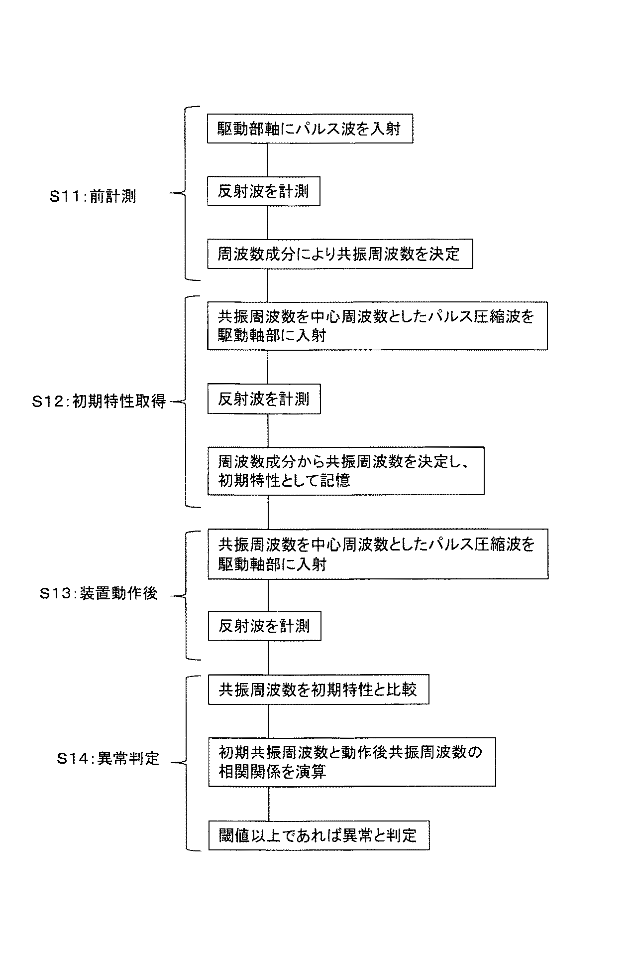
図4は、検査方法のフローチャートを示す説明図である。
以下、判定方法の詳細を説明する。
(S11;前計測)
まず、ガス絶縁開閉装置の組立て後(初期状態)に、処理部51は、駆動部3に発振器2からパルス波等の入射信号を入力する。なお、ここで組立て後(初期状態)については、例えば、ガス絶縁開閉装置を閉極状態として稼働した後であって、組立て直後の予め定めた時間後、安定状態・定常状態となった後等、適宜のタイミングを初期状態として定めることができる。発振器2は、例えば、遮断器や断路器の駆動部3において、外部からアクセス可能な駆動軸等に接触し、振動を駆動部3に伝達させる。入射波形は、例えば、インパルス波、もしくは圧縮パルス波など、適宜のものを用いることができる。処理部51は、駆動部3からの反射波(反射信号)を受信部4のセンサにより計測し、波形データ記憶部5に記憶する。なお、各記憶部・格納部へのデータの記録の際は、時刻、周波数、波形情報、各種識別情報等を適宜含めることができる。処理部51は、波形データ記憶部5から波形データを読み出し、この反射信号において時間領域信号をフーリエ変換部6で周波数成分データとし、駆動部の予め定めた複数の共振周波数を取得する。上述を前計測とする。
FIG. 4 is an explanatory diagram showing a flowchart of the inspection method.
Details of the determination method will be described below.
(S11; pre-measurement)
First, after the gas insulated switchgear is assembled (initial state), the
図2は、駆動部の受信波の周波数成分データを示す説明図である。ここで、共振周波数F1、F2、・・・としては、例えば、強度の比較的強い周波数から予め定めた数を選択することができる。なお、低周波数は比較的ノイズが含まれる場合が想定され、また、高周波数は減衰して計測しにくい場合等が想定されるが、予め定めた周波数以下及び/又は以上の周波数を除くようにしてもよい。 FIG. 2 is an explanatory diagram showing frequency component data of the received wave of the drive unit. Here, as the resonance frequencies F 1 , F 2 ,..., For example, a predetermined number can be selected from relatively strong frequencies. The low frequency is assumed to contain relatively noise, and the high frequency is assumed to be attenuated and difficult to measure. However, the frequency below and / or above the predetermined frequency should be excluded. May be.
(S12;初期特性取得)
さらに、処理部51は、発振器2により、前計測でのパルス波による反射波で得た複数の共振周波数F1、F2、・・・を中心周波数とした各パルス圧縮波等の入射信号を駆動部3に入射して上述のように、受信部4、波形データ記憶部5、フーリエ変換部6等を用いてより細密な周波数特性を得る。処理部51は、この際得られた共振周波数f1、f2、f3、・・・を初期周波数特性とし、初期周波数特性格納部7に記録する。ここで、周波数f1、f2は、それぞれ周波数F1、F2を入射して、得られた反射信号により計測された細密な共振周波数である。
(S12; initial characteristic acquisition)
Further, the
(S13;装置動作後)
ガス絶縁開閉装置の運用開始後、処理部51は、初期周波数特性格納部7を参照し、共振周波数f1、f2、f3、・・・を得て、上述と同様に各共振周波数f1、f2、f3、・・・を中心としたパルス圧縮波の入射に対する反射波により共振周波数f1’、f2’、f3’、・・・を求め、運用周波数特性を運用周波数特性格納部8に記録する。
(S13; after device operation)
After starting the operation of the gas insulated switchgear, the
(S14;異常判定)
図3は、初期周波数特性における共振周波数と装置運用開始後の共振周波数との相関関係を示す説明図である。
処理部51は、初期周波数特性における共振周波数f1、f2、f3、・・・と装置運用開始後の共振周波数f1’、f2’、f3’、・・・との相関関係を相関関係演算部9で計算する。処理部51は、例えば、相関関係として横軸に初期特性、縦軸に経過時間後の特性とし、相関の閾値を設定し、この閾値を超えた場合に異常と判定する。より具体的には初期の共振周波数f1に対してはf1’、f2に対してはf2’と言うように対応する共振周波数の組を設定する。駆動部3のリンク、もしくはギア部に固渋などの異常が発生すると駆動部3の固有振動数が変化するため、共有振動数にずれが生じる。例えば、このずれが閾値を超過した場合に異常と判定することができる。閾値の設定は、例えば、別途要素試験において正常時の共振振動数に対して模式的に固渋状態とした場合の共振周波数のずれを基に設定することができる。うち、ずれ量は、例えば、対応した共振周波数の組における相関関係上のユークリッド距離等の各種計算方法にて計算することができる。処理部51は、前述の判定を各中心周波数ごとに実施し、中心周波数ごとの判定結果を各共振周波数の相関関係格納部10に記録する。処理部51は、相関関係評価部11にて、例えば、各相関関係格納部10の結果を用いて異常と判定された周波数の数、及び異常の度合いを判定して、異常の状態を評価する。なお、異常の度合いは、例えば、ずれの量を予め定めた閾値と比較すること等により行うことができる。また、異常の状態の評価は、例えば、異常と判定された数、異常の度合いを予め定めた重み等で加算又は積算することで指標を求め、この指標を予め定めた閾値と比較すること等により行うことができる。処理部51は、上述の評価結果を評価結果表示部/記憶部12にて表示及び/又は記憶する。(図4)なお、表示方法としては、例えば、異常の有無、時間、駆動部識別情報等や、図3に示す相関図等を適宜表示することができる。
(S14: abnormality determination)
FIG. 3 is an explanatory diagram showing the correlation between the resonance frequency in the initial frequency characteristics and the resonance frequency after the start of operation of the apparatus.
The
[入射波形]
本システムにおいて、上述のように、駆動部3に発振器2からパルス波を入力する。発振器2は遮断器や断路器等の駆動部3において、外部からアクセス可能な駆動軸に接触し、振動を駆動部に伝達させる。
[Incoming waveform]
In the present system, a pulse wave is input from the
図7は、インパルス波形例を示す説明図である。
図4に示した前計測(S11)においては、入力波形は、例えば、図7に示すようなインパルス波形とすることができる。図7(a)に信号強度の時間特性を示し、図7(b)にその周波数特性を示す。このような波形は、複数の共振周波数を得るための幅広い周波数特性を含む。
FIG. 7 is an explanatory diagram showing an example of an impulse waveform.
In the pre-measurement (S11) shown in FIG. 4, the input waveform can be an impulse waveform as shown in FIG. 7, for example. FIG. 7A shows the time characteristics of signal strength, and FIG. 7B shows the frequency characteristics. Such a waveform includes a wide range of frequency characteristics for obtaining a plurality of resonance frequencies.
図5は、パルス圧縮波を示す説明図である。
各共振周波数での入射波形は、例えば、図5に示すようにパルス圧縮波とすることができる。図5(a)は、信号強度の時間特性を示し、図5(b)はその中心周波数を有する周波数特性を示す。本システムでは、この圧縮波の中心周波数を初期状態の共振振動数f1、f2、f3、・・・として少なくとも2種類以上入射し、それぞれの反射波における周波数特性を運用周波数特性格納部8に記録する。ガス絶縁開閉装置の運用開始後の計測においても、上述と同様の種類の中心周波数のパルス圧縮波を入射し、反射特性を計測する。これにより取得した時間経過後の周波数特性として共振周波数の近傍周波数でより精細に取得することが可能となる。
FIG. 5 is an explanatory diagram showing a pulse compression wave.
The incident waveform at each resonance frequency can be, for example, a pulse compression wave as shown in FIG. FIG. 5A shows a time characteristic of signal strength, and FIG. 5B shows a frequency characteristic having the center frequency. In this system, at least two types of the center frequency of the compression wave are incident as the resonance frequencies f1, f2, f3,... In the initial state, and the frequency characteristics of each reflected wave are recorded in the operating frequency characteristic storage unit 8. To do. Also in the measurement after the start of operation of the gas insulated switchgear, a pulse compression wave having the same type of center frequency as that described above is incident and the reflection characteristics are measured. As a result, it is possible to acquire the frequency characteristics after the time has elapsed more precisely at a frequency near the resonance frequency.
[相関関係の演算]
初期周波数特性格納部7に記録した初期周波数特性f1、f2、f3、・・・と、運用周波数特性格納部8に格納した経過時間後の周波数特性f1’、f2’、f3’、・・・との相関関係を相関関係演算部9で計算する方法として、例えば、初期周波数特性と経過時間後の周波数特性とのマハラノビス距離を用いて判定することができる。この際、データがn次元の連続ベクトルであるとして、得られたデータ列をxm=x1, x2, x3,... xmとして、i番目のデータを、
The initial frequency characteristics f1, f2, f3,... Recorded in the initial frequency characteristic storage unit 7, and the frequency characteristics f1 ′, f2 ′, f3 ′,. As a method for calculating the correlation between the initial frequency characteristic and the frequency characteristic after the elapsed time, for example, the correlation calculation unit 9 can determine the correlation using the Mahalanobis distance. At this time, assuming that the data is an n-dimensional continuous vector, the obtained data string is represented by x m = x 1 , x 2 , x 3 ,. . . as x m, the i-th data,
この他にも、相関を計算する方法として、例えば、母集団相関係数、標本相関係数、ピアソンの積分相関係数等、適宜の方法を用いることができる。
In addition, as a method for calculating the correlation, for example, an appropriate method such as a population correlation coefficient, a sample correlation coefficient, a Pearson integral correlation coefficient, or the like can be used.
C.第2の実施形態
図6は、ガス絶縁開閉装置を遠隔監視するための駆動部検査システムの構成図である。
本システムは、ガス絶縁開閉装置100−2、検査装置200−2を備える。本システムにおいては、発振器2と受信器4をあらかじめ駆動部3の軸に組み込んだ状態(表面等に取り付けた状態)でガス絶縁開閉装置100−2を構成する。信号発生器1と受信器4は、データ処理部13−1に接続される。データ処理部13−1はメモリ52内の適宜ひとつ又は複数の構成(波形データ記憶部5等)や処理部51の適宜のひとつ又は複数の構成(相関関係演算部9等)を有し、データ処理部13−2は、それ以外のメモリ52及び処理部51のひとつ又は複数の構成を有する。データ処理部13−1は、有線又は無線の適宜の通信回線やネットワークと通信装置14を介してオンライン又はオフラインで集中管理室15のデータ処理部13−2に接続されており、集中管理室15では、任意の時間にデータを取得、表示及び/又は、記憶することが可能となる。
C. Second embodiment
FIG. 6 is a configuration diagram of a drive unit inspection system for remotely monitoring the gas insulated switchgear.
This system includes a gas insulated switchgear 100-2 and an inspection device 200-2. In this system, the gas insulated switchgear 100-2 is configured in a state in which the
D.第3の実施形態(モード計測)
上述の本実施形態において、発振器2と受信器4を2個以上設置するようにしてもよい。一例として、ひとつの発振器2と2個の受信器4を備え、ひとつの発振器2を駆動部3の主軸に設置し、受信器4の一つを主軸に設置し、他の受信器4を駆動部3の副軸に設置することができる。処理部51は、発振器2から入力した信号に対する反射波をそれぞれの受信器4で受信し、上述のように周波数特性を取得する。なお、発振器2も複数設けるようにしてもよい。処理部51は、発振器2と受信器4の設置場所、及びセンサの組合せをパラメータとして追加するようにしてもよい。これにより駆動部3の振動のモード計測(例えば、主軸によるモード、副軸によるモード等)が可能となり、駆動部3の異常の内容についての判定が可能となる。
D. Third embodiment (mode measurement)
In the above-described embodiment, two or
E.実施形態の効果
本実施形態により、ガス絶縁開閉装置の駆動部が動作していない状態(通常の通電時等)においても、駆動部の異常判定が可能となるため、ガス絶縁開閉装置を停止して駆動部を解体して検査する必要がなく、さらに電力系統の切り替え、停止なしにガス絶縁開閉装置の検査が可能となるため、検査期間の大幅な短縮が図れる。加えて、機器の停止なしに検査ができるため、任意の時間間隔で検査データが取得でき、時系列データが取得可能となり、機器の信頼性が向上する。
E. Effects of the embodiment
According to the present embodiment, even when the drive unit of the gas insulated switchgear is not operating (during normal energization, etc.), it is possible to determine the abnormality of the drive unit. There is no need to disassemble and inspect, and furthermore, the gas insulated switchgear can be inspected without switching or stopping the power system, so the inspection period can be greatly shortened. In addition, since inspection can be performed without stopping the apparatus, inspection data can be acquired at arbitrary time intervals, and time-series data can be acquired, improving the reliability of the apparatus.
F.付記
なお、本発明は上記した実施例に限定されるものではなく、様々な変形例が含まれている。例えば、上記した実施例は本発明を分かりやすく説明するために詳細に説明したものであり、必ずしも説明した全ての構成を備えるものに限定されるものではない。また、ある実施例の構成の一部を他の実施例の構成に置き換えることが可能であり、また、ある実施例の構成に他の実施例の構成を加えることも可能である。また、各実施例の構成の一部について、他の構成の追加・削除・置換をすることが可能である。
また、上記の各構成、機能、処理部、処理手段等は、それらの一部又は全部を、例えば集積回路で設計する等によりハードウェアで実現してもよい。また、上記の各構成、機能等は、プロセッサがそれぞれの機能を実現するプログラムを解釈し、実行することによりソフトウェアで実現してもよい。各機能を実現するプログラム、テーブル、ファイル等の情報は、メモリや、ハードディスク、SSD(Solid State Drive)等の記録装置、又は、ICカード、SDカード、DVD等の記録媒体に置くことができる。
また、制御線や情報線は説明上必要と考えられるものを示しており、製品上必ずしも全ての制御線や情報線を示しているとは限らない。実際には殆ど全ての構成が相互に接続されていると考えてもよい。
F. Appendix
In addition, this invention is not limited to an above-described Example, Various modifications are included. For example, the above-described embodiments have been described in detail for easy understanding of the present invention, and are not necessarily limited to those having all the configurations described. Further, a part of the configuration of one embodiment can be replaced with the configuration of another embodiment, and the configuration of another embodiment can be added to the configuration of one embodiment. Further, it is possible to add, delete, and replace other configurations for a part of the configuration of each embodiment.
Each of the above-described configurations, functions, processing units, processing means, and the like may be realized by hardware by designing a part or all of them with, for example, an integrated circuit. Each of the above-described configurations, functions, and the like may be realized by software by interpreting and executing a program that realizes each function by the processor. Information such as programs, tables, and files for realizing each function can be stored in a recording device such as a memory, a hard disk, or an SSD (Solid State Drive), or a recording medium such as an IC card, an SD card, or a DVD.
Further, the control lines and information lines indicate what is considered necessary for the explanation, and not all the control lines and information lines on the product are necessarily shown. Actually, it may be considered that almost all the components are connected to each other.
1;信号発生器、2;発振器、3;駆動部、4;受信器、5;波形データ記憶部、6;フーリエ変換部、7;初期周波数特性格納部;運用周波数特性格納部、9;相関関係演算部、10;相関関係格納部、11;相関関係評価部、12;評価結果表示部/記憶部、13;データ処理装置、14;通信装置、15;集中管理室、16;通信線
DESCRIPTION OF SYMBOLS 1; Signal generator, 2; Oscillator, 3; Drive part, 4; Receiver, 5; Waveform data storage part, 6: Fourier-transform part, 7: Initial frequency characteristic storage part; Operation frequency characteristic storage part, 9; Correlation calculation unit, 10; correlation storage unit, 11; correlation evaluation unit, 12; evaluation result display unit / storage unit, 13; data processing device, 14; communication device, 15; centralized management room, 16;
Claims (15)
発振器と、
受信器と、
処理部と、
を備え、
前記処理部は、
開閉装置の初期状態において、駆動部に前記発振器から第1の入射信号を入力し、駆動部から受信部により受信した周波数成分から複数の第1の共振周波数を取得し、
各第1の共振周波数を中心周波数とした各第2の入射信号を前記発振器により駆動部に入射して、駆動部から受信部により受信した各第2の反射信号の周波数成分から各第2の共振周波数を得て、
開閉装置の運用開始後において、各第2の共振周波数を中心周波数とした各第2の入射信号を前記発振器により駆動部に入射して、駆動部から受信部により受信した各第3の反射信号の周波数成分から各第3の共振周波数を得て、
各第2の共振周波数と各第3の共振周波数との相関関係から異常を判定する、
開閉装置の検査装置。
An inspection device for a switchgear,
An oscillator,
A receiver,
A processing unit;
With
The processor is
In an initial state of the switchgear, a first incident signal is input from the oscillator to the drive unit, and a plurality of first resonance frequencies are obtained from frequency components received by the reception unit from the drive unit,
Each second incident signal having each first resonance frequency as a center frequency is incident on the driving unit by the oscillator, and each second reflected signal is received from the frequency component of each second reflected signal received from the driving unit by the receiving unit. Get the resonance frequency,
After the start of operation of the switchgear, each third reflected signal received by the receiving unit from the driving unit after each second incident signal having the second resonance frequency as the center frequency is incident on the driving unit by the oscillator. Obtaining each third resonance frequency from the frequency components of
An abnormality is determined from the correlation between each second resonance frequency and each third resonance frequency.
Inspection device for switchgear.
前記処理部は、
フーリエ変換部と、
相関関係演算部と、
初期周波数特性格納部と
運用周波数特性格納部と、
相関関係格納部と、
を備え、
前記フーリエ変換部は、開閉装置の初期状態において、第1の反射信号の周波数成分から複数の第1の共振周波数を取得し、各第2の反射信号の周波数成分から各第2の共振周波数を得て、前記初期周波数特性格納部に記憶し、
前記フーリエ変換部は、開閉装置の運用開始後において、各第3の反射信号の周波数成分から各第3の共振周波数を得て、前記運用周波数特性格納部に記憶し、
前記相関関係演算部は、前記初期周波数特性格納部及び前記運用周波数特性格納部とを参照し、各第2の共振周波数と各第3の共振周波数との相関関係のずれから異常を第2の共振周波数ごとに実行し、前記相関関係格納部に判定結果を記憶する、
ことを特徴とする開閉装置の検査装置。
The inspection apparatus for a switchgear according to claim 1,
The processor is
A Fourier transform unit;
A correlation calculation unit;
An initial frequency characteristic storage, an operating frequency characteristic storage,
A correlation store;
With
The Fourier transform unit obtains a plurality of first resonance frequencies from the frequency components of the first reflected signal in an initial state of the switchgear, and calculates each second resonance frequency from the frequency components of the second reflected signals. And store it in the initial frequency characteristic storage unit,
The Fourier transform unit obtains each third resonance frequency from the frequency component of each third reflected signal after starting the operation of the switchgear, and stores the third resonance frequency in the operation frequency characteristic storage unit,
The correlation calculation unit refers to the initial frequency characteristic storage unit and the operating frequency characteristic storage unit, and determines a second abnormality from a deviation in correlation between each second resonance frequency and each third resonance frequency. Execute for each resonance frequency, and store the determination result in the correlation storage unit,
An inspection device for a switchgear characterized by the above.
前記処理部は、前記相関関係格納部を参照し、異常と判定された第2及び第3の共振周波数の数及び/又は異常の度合いから異常の状態を評価する相関関係評価部を、さらに備えたことを特徴とする開閉装置の検査装置。
The inspection apparatus for a switchgear according to claim 2,
The processing unit further includes a correlation evaluation unit that refers to the correlation storage unit and evaluates an abnormal state from the number and / or degree of abnormality of the second and third resonance frequencies determined to be abnormal. An inspection device for a switchgear characterized by the above.
前記相関関係評価部は、評価結果を評価結果表示部に表示する及び/又は評価結果記憶部に記憶する及び/又は他の装置に出力することを特徴とする開閉装置の検査装置。
In the inspection apparatus of the switchgear according to claim 3,
The correlation evaluation unit displays the evaluation result on the evaluation result display unit and / or stores it in the evaluation result storage unit and / or outputs it to another device.
前記発振器は、遮断器及び/又は断路器及び/又は開閉装置の他の駆動部において、外部からアクセス可能な駆動軸に接触して振動を駆動部に伝達させるように取り付けられたことを特徴とする開閉装置の検査装置。
The inspection apparatus for a switchgear according to claim 1,
The oscillator is attached so as to contact an externally accessible drive shaft and transmit vibration to the drive unit in another circuit breaker and / or disconnector and / or other drive unit of the switchgear. Inspection device for opening and closing device.
前記発振器は、入射信号として、初期状態ではインパルス波、運転開始後はパルス圧縮波を用いることを特徴とする開閉装置の検査装置。
The inspection apparatus for a switchgear according to claim 1,
An inspection device for a switchgear, wherein the oscillator uses an impulse wave as an incident signal in an initial state and a pulse compression wave after the start of operation.
前記処理部は、第2の共振周波数と第3の共振周波数とのずれ量を、対応した共振周波数の組におけるユークリッド距離、マハラノビス距離、ピアソンの積分相関係数、又は、その他の相関係数のいずれかを用いて判定することを特徴とする開閉装置の検査装置。
The inspection apparatus for a switchgear according to claim 1,
The processing unit calculates a deviation amount between the second resonance frequency and the third resonance frequency by using a Euclidean distance, a Mahalanobis distance, a Pearson integral correlation coefficient, or another correlation coefficient in a corresponding resonance frequency set. An inspection device for a switchgear, characterized in that determination is made using either one.
前記発振器及び前記受信器が、開閉装置の駆動部に予め取り付けられた又は予め組み込まれていることを特徴とする開閉装置の検査装置。
The inspection apparatus for a switchgear according to claim 1,
An inspection apparatus for a switchgear, wherein the oscillator and the receiver are attached in advance or incorporated in a drive unit of the switchgear.
前記発振器及び/又は前記受信器を複数設け、
前記処理部は、前記発振器と前記受信器の組み合わせにより駆動部の複数の振動モードによる第1乃至第3の反射信号を取得し、異常の判定を行うことを特徴とする開閉装置の検査装置。
The inspection apparatus for a switchgear according to claim 1,
A plurality of the oscillator and / or the receiver are provided,
An inspection apparatus for a switchgear, wherein the processing unit acquires first to third reflected signals in a plurality of vibration modes of a driving unit by a combination of the oscillator and the receiver, and performs abnormality determination.
ひとつの前記発振器を駆動部の主軸又は第1の軸に設置し,前記受信器のひとつを主軸又は第1の軸に設置し,他の前記受信器を駆動部の副軸又は第2の軸に設置し、
前記発振器から入力した信号に対する第1乃至第3の反射信号を各前記受信器で受信し,第1乃至第3の共振周波数を取得する、
ことを特徴とする開閉装置の検査装置。
The inspection apparatus for a switchgear according to claim 9,
One oscillator is installed on the main axis or the first axis of the drive unit, one of the receivers is installed on the main axis or the first axis, and the other receiver is installed on the auxiliary axis or the second axis of the drive unit. Installed in
The first to third reflected signals with respect to the signal input from the oscillator are received by the receivers, and first to third resonance frequencies are obtained.
An inspection device for a switchgear characterized by the above.
前記処理部は、第1乃至第3の共振周波数、相関関係のうちひとつ又は複数をそれぞれ記憶部に書き込み及び記憶部から読み取ることを特徴とする開閉装置の検査装置。
The inspection apparatus for a switchgear according to claim 1,
An inspection apparatus for a switchgear, wherein the processing unit writes one or more of the first to third resonance frequencies and correlations to and from the storage unit.
前記開閉装置は、ガス絶縁開閉装置であることを特徴とする開閉装置の検査装置。
The inspection apparatus for a switchgear according to claim 1,
The switchgear inspection device, wherein the switchgear is a gas insulated switchgear.
開閉装置の駆動部に予め取り付けられ又は予め組み込まれて第1の入射信号を入射する前記発振器と、開閉装置の駆動部に予め取り付けられ又は予め組み込まれて駆動部からの第1の反射信号を受信する前記受信器と、を有する開閉装置と、
検査装置と、
を備え、
前記検査装置は、
開閉装置の初期状態において、駆動部に前記発振器から第1の入射信号を入力し、駆動部から受信部により受信した周波数成分から複数の第1の共振周波数を取得する、第1の処理機能部と、
各第1の共振周波数を中心周波数とした各第2の入射信号を前記発振器により駆動部に入射して、駆動部から受信部により受信した各第2の反射信号の周波数成分から各第2の共振周波数を得る、第2の処理機能部、
開閉装置の運用開始後において、各第2の共振周波数を中心周波数とした各第2の入射信号を前記発振器により駆動部に入射して、駆動部から受信部により受信した各第3の反射信号の周波数成分から各第3の共振周波数を得る、第3の処理機能部と、
各第2の共振周波数と各第3の共振周波数との相関関係から異常を判定する、第4の処理機能部と、
を備えた開閉装置の検査システム。
A switchgear inspection system,
The oscillator that is pre-attached or incorporated in the drive unit of the switchgear and receives the first incident signal; and the first reflected signal from the drive unit that is pre-attached or preinstalled in the switcher of the switchgear An opening and closing device comprising:
An inspection device;
With
The inspection device includes:
A first processing function unit that inputs a first incident signal from the oscillator to the driving unit and acquires a plurality of first resonance frequencies from frequency components received by the receiving unit from the driving unit in an initial state of the switchgear When,
Each second incident signal having each first resonance frequency as a center frequency is incident on the driving unit by the oscillator, and each second reflected signal is received from the frequency component of each second reflected signal received from the driving unit by the receiving unit. A second processing function unit for obtaining a resonant frequency;
After the start of operation of the switchgear, each third reflected signal received by the receiving unit from the driving unit after each second incident signal having the second resonance frequency as the center frequency is incident on the driving unit by the oscillator. A third processing function unit for obtaining each third resonance frequency from the frequency components of
A fourth processing function unit for determining abnormality from the correlation between each second resonance frequency and each third resonance frequency;
Inspection system for switchgear equipped with
前記受信器、又は、前記検査装置の第1乃至第n(nは、2〜4の整数)処理機能部を有する第1のデータ処理部と、
前記第1のデータ処理部とネットワーク又はラインを介して接続され、前記検査装置の第n乃至第4の処理機能部を有する第2のデータ処理部を備え、任意の時間に、前記第1のデータ処理部から、第1乃至第nの処理機能部のいずれかひとつ又は複数の出力データを取得する集中管理室と、
をさらに備えたことを特徴とする開閉装置の検査システム。
The inspection system for a switchgear according to claim 13,
A first data processing unit having first to nth (n is an integer of 2 to 4) processing function units of the receiver or the inspection device;
The second data processing unit is connected to the first data processing unit via a network or a line and includes the nth to fourth processing function units of the inspection apparatus. A centralized management room for acquiring any one or a plurality of output data of the first to n-th processing function units from the data processing unit;
An inspection system for a switchgear characterized by further comprising:
開閉装置の初期状態において、駆動部に前記発振器から第1の入射信号を入力し、駆動部から受信部により受信した周波数成分から複数の第1の共振周波数を取得し、
各第1の共振周波数を中心周波数とした各第2の入射信号を前記発振器により駆動部に入射して、駆動部から受信部により受信した各第2の反射信号の周波数成分から各第2の共振周波数を得て、
開閉装置の運用開始後において、各第2の共振周波数を中心周波数とした各第2の入射信号を前記発振器により駆動部に入射して、駆動部から受信部により受信した各第3の反射信号の周波数成分から各第3の共振周波数を得て、
各第2の共振周波数と各第3の共振周波数との相関関係から異常を判定する、
開閉装置の検査方法。
An inspection method for a switchgear,
In an initial state of the switchgear, a first incident signal is input from the oscillator to the drive unit, and a plurality of first resonance frequencies are obtained from frequency components received by the reception unit from the drive unit,
Each second incident signal having each first resonance frequency as a center frequency is incident on the driving unit by the oscillator, and each second reflected signal is received from the frequency component of each second reflected signal received from the driving unit by the receiving unit. Get the resonance frequency,
After the start of operation of the switchgear, each third reflected signal received by the receiving unit from the driving unit after each second incident signal having the second resonance frequency as the center frequency is incident on the driving unit by the oscillator. Obtaining each third resonance frequency from the frequency components of
An abnormality is determined from the correlation between each second resonance frequency and each third resonance frequency.
Inspection method for switchgear.
Priority Applications (1)
| Application Number | Priority Date | Filing Date | Title |
|---|---|---|---|
| JP2016218603A JP2018077110A (en) | 2016-11-09 | 2016-11-09 | Switchgear inspection device and system and method |
Applications Claiming Priority (1)
| Application Number | Priority Date | Filing Date | Title |
|---|---|---|---|
| JP2016218603A JP2018077110A (en) | 2016-11-09 | 2016-11-09 | Switchgear inspection device and system and method |
Publications (1)
| Publication Number | Publication Date |
|---|---|
| JP2018077110A true JP2018077110A (en) | 2018-05-17 |
Family
ID=62148970
Family Applications (1)
| Application Number | Title | Priority Date | Filing Date |
|---|---|---|---|
| JP2016218603A Pending JP2018077110A (en) | 2016-11-09 | 2016-11-09 | Switchgear inspection device and system and method |
Country Status (1)
| Country | Link |
|---|---|
| JP (1) | JP2018077110A (en) |
Cited By (2)
| Publication number | Priority date | Publication date | Assignee | Title |
|---|---|---|---|---|
| CN116256627A (en) * | 2023-04-14 | 2023-06-13 | 北京新能源汽车股份有限公司 | Relay adhesion detection circuit and charging equipment |
| JP2024538713A (en) * | 2021-10-07 | 2024-10-23 | シェブロン ユー.エス.エー. インコーポレイテッド | Structural Inspection Using Multitone Steady-State Excitation |
-
2016
- 2016-11-09 JP JP2016218603A patent/JP2018077110A/en active Pending
Cited By (3)
| Publication number | Priority date | Publication date | Assignee | Title |
|---|---|---|---|---|
| JP2024538713A (en) * | 2021-10-07 | 2024-10-23 | シェブロン ユー.エス.エー. インコーポレイテッド | Structural Inspection Using Multitone Steady-State Excitation |
| JP7838083B2 (en) | 2021-10-07 | 2026-03-31 | シェブロン ユー.エス.エー. インコーポレイテッド | Structural inspection using multitone steady-state excitation |
| CN116256627A (en) * | 2023-04-14 | 2023-06-13 | 北京新能源汽车股份有限公司 | Relay adhesion detection circuit and charging equipment |
Similar Documents
| Publication | Publication Date | Title |
|---|---|---|
| KR102264773B1 (en) | Fault Diagnosis System for Diagnosis and Control of Temperature, Partial Discharge and Noise of Transformers Using Sensors | |
| KR101571877B1 (en) | Closed type switchboard including diagnostic apparatus | |
| JP7003703B2 (en) | Partial discharge detection device using multi-sensor | |
| JP5079878B2 (en) | Remote monitoring device | |
| US20200217895A1 (en) | Abnormality diagnosis device, abnormality diagnosis method, and abnormality diagnosis system | |
| KR101550689B1 (en) | A arc or corona detection system for a distributing board with the acoustic emission sensor and noise removal function | |
| KR101574528B1 (en) | Diagnostic monitoring system for power equipment | |
| CN112020822A (en) | System, method and computer program product for detecting a physical parameter of at least one component of a tap transformer and for monitoring components of a tap transformer | |
| JP2015078882A (en) | Insulation diagnostic device | |
| KR20080076328A (en) | Remote partial discharge diagnosis system and method for power equipment using frequency / phase spectrum | |
| JP7443269B2 (en) | Insulation diagnosis system and insulation diagnosis method | |
| JP2020030125A (en) | Abnormality diagnosis device and abnormality diagnosis method | |
| CN103135041A (en) | Transformer/ electric reactor partial discharge on-line monitoring method and transformer/ electric reactor partial discharge on-line monitoring system | |
| US9188632B1 (en) | Self learning radio frequency monitoring system for identifying and locating faults in electrical distribution systems | |
| CN111551352A (en) | A method and system for detecting the state of a circuit breaker of a GIS equipment | |
| JP6789872B2 (en) | Analytical methods, analyzers, and programs | |
| CN111108400B (en) | Method and device for detecting partial discharges in an electrical operating mechanism | |
| US20250298406A1 (en) | Adaptive condition-based machine health monitoring | |
| KR102743237B1 (en) | Switchboard(High pressure board, Low pressure board, Distribution board) Monitoring Overheating and Insulation Abnormalities | |
| US20250239427A1 (en) | Circuit Breaker Monitoring System | |
| CN110858068A (en) | Branch circuit thermal monitoring system | |
| KR101268474B1 (en) | Predictive diagnostic method and system on mechanical integrity of generator stator | |
| KR100728762B1 (en) | Partial discharge and interlayer short circuit online monitoring system of high voltage rotating equipment | |
| CN111044272A (en) | High-voltage circuit breaker mechanical characteristic test method and device based on big data technology | |
| CN221571661U (en) | Monitoring device for circuit breaker |
Legal Events
| Date | Code | Title | Description |
|---|---|---|---|
| RD02 | Notification of acceptance of power of attorney |
Free format text: JAPANESE INTERMEDIATE CODE: A7422 Effective date: 20170313 |
|
| RD04 | Notification of resignation of power of attorney |
Free format text: JAPANESE INTERMEDIATE CODE: A7424 Effective date: 20170317 |