JP2018090102A - Pneumatic tire - Google Patents
Pneumatic tire Download PDFInfo
- Publication number
- JP2018090102A JP2018090102A JP2016235341A JP2016235341A JP2018090102A JP 2018090102 A JP2018090102 A JP 2018090102A JP 2016235341 A JP2016235341 A JP 2016235341A JP 2016235341 A JP2016235341 A JP 2016235341A JP 2018090102 A JP2018090102 A JP 2018090102A
- Authority
- JP
- Japan
- Prior art keywords
- rim
- bead base
- base surface
- bead
- groove
- Prior art date
- Legal status (The legal status is an assumption and is not a legal conclusion. Google has not performed a legal analysis and makes no representation as to the accuracy of the status listed.)
- Granted
Links
Images



Landscapes
- Tires In General (AREA)
Abstract
【課題】ビードベース面での空気漏れとリムずれを効果的に防止する。【解決手段】ビードベース面5の内側領域以外に、タイヤ幅方向に延びタイヤ周方向に並設される複数の凹部9又は凸部からなるリムずれ防止部が形成されている。【選択図】図1PROBLEM TO BE SOLVED: To effectively prevent air leakage and rim displacement on a bead base surface. SOLUTION: In addition to the inner region of a bead base surface 5, a rim slip prevention portion composed of a plurality of concave portions 9 or convex portions extending in the tire width direction and juxtaposed in the tire circumferential direction is formed. [Selection diagram] Fig. 1
Description
本発明は、空気入りタイヤに関するものである。 The present invention relates to a pneumatic tire.
従来、空気入りタイヤとして、ビードベース面に、タイヤ周方向に対して傾斜して延びるリムずれ防止用の突条を形成したものが公知である(例えば、特許文献1参照)。
また他の空気入りタイヤとして、ビードベース面に、タイヤ軸方向に沿って延びる凸条をタイヤ周方向に複数形成したものが公知である(例えば、特許文献2参照)。
さらに他の空気入りタイヤとして、ビードベース面に、タイヤ周方向に不連続で、かつビードトウとビードヒールを連結させない凹部を形成したものが公知である(例えば、特許文献3参照)。
2. Description of the Related Art Conventionally, a pneumatic tire is known in which a bead base surface is provided with a rim slip prevention protrusion extending in an inclined manner with respect to the tire circumferential direction (see, for example, Patent Document 1).
Another pneumatic tire is known in which a plurality of ridges extending in the tire axial direction are formed on the bead base surface in the tire circumferential direction (see, for example, Patent Document 2).
Further, another pneumatic tire is known in which a bead base surface is formed with a recess that is discontinuous in the tire circumferential direction and does not connect the bead toe and the bead heel (see, for example, Patent Document 3).
しかしながら、前記いずれの空気入りタイヤであっても、ビードベース面に於けるタイヤ幅方向への空気の漏れとリム外れについて考慮したものはない。 However, in any of the pneumatic tires described above, there is no consideration for air leakage and rim removal on the bead base surface in the tire width direction.
本発明は、ビードベース面での空気漏れとリムずれを効果的に防止する空気入りタイヤを提供することを課題とする。 An object of the present invention is to provide a pneumatic tire that effectively prevents air leakage and rim displacement on the bead base surface.
本発明は、前記課題を解決するための手段として、
ビードベース面の内側領域以外に、タイヤ幅方向に延びタイヤ周方向に並設される複数の凹部又は凸部からなるリムずれ防止部が形成されていることを特徴とする空気入りタイヤを提供する。
As a means for solving the above problems, the present invention provides:
Provided is a pneumatic tire characterized in that, in addition to the inner region of the bead base surface, a rim displacement prevention portion is formed which includes a plurality of recesses or protrusions extending in the tire width direction and arranged in parallel in the tire circumferential direction. .
この構成により、ビードベース面の内側領域はリムに対して面接触させることができ、空気漏れを防止可能となる。また、ビードベース面の内側領域以外に形成した凹部又は凸部によってリムずれを防止できる。 With this configuration, the inner region of the bead base surface can be brought into surface contact with the rim, and air leakage can be prevented. Further, rim displacement can be prevented by a concave portion or a convex portion formed outside the inner region of the bead base surface.
前記内側領域は、前記ビードベース面のビードトウから、ビードベース幅の5%以上15%以下の長さの範囲であるのが好ましい。 The inner region preferably ranges from a bead toe on the bead base surface to a length of 5% to 15% of the bead base width.
この構成により、リムに面接触する内側領域での空気漏れに対して十分な面積を確保することができる。 With this configuration, it is possible to ensure a sufficient area against air leakage in the inner region that is in surface contact with the rim.
前記リムずれ防止部は、溝部であるのが好ましい。 It is preferable that the rim deviation preventing portion is a groove portion.
この構成により、タイヤ周方向には溝部によって形成されるエッジがリムに作用してリムずれを防止する。また、ビードベース面には溝部を設けただけであるので、タイヤ幅方向には、殆ど隙間が形成されず、空気漏れも発生しない。 With this configuration, an edge formed by the groove portion acts on the rim in the tire circumferential direction to prevent rim displacement. Further, since only a groove is provided on the bead base surface, almost no gap is formed in the tire width direction, and no air leakage occurs.
前記溝部は、屈曲部を有するのが好ましい。 The groove part preferably has a bent part.
この構成により、溝部によって形成されるエッジ長さを長くすることができ、より一層、リムずれ及び空気漏れしにくくすることが可能となる。 With this configuration, it is possible to increase the length of the edge formed by the groove, and it is possible to further prevent rim displacement and air leakage.
前記溝部は、ビードベース面内で多角形を構成するように配置されているのが好ましい。 The groove is preferably arranged so as to form a polygon within the bead base surface.
この構成により、コーナリング等で多方向に力が作用する場合であっても、有効にリムずれを防止することができる。 With this configuration, even when force is applied in multiple directions by cornering or the like, rim displacement can be effectively prevented.
本発明によれば、ビードベース面の内側領域にはリムずれ防止部が形成されておらず、リムに対して内側領域を全面接触させることができるので、空気漏れを効果的に防止可能となる。また、ビードベース面の内側領域以外にはリムずれ防止部が形成されているので、走行時、特に制動時のリムずれを防止できる。 According to the present invention, no rim displacement prevention portion is formed in the inner region of the bead base surface, and the entire inner region can be brought into contact with the rim, so that air leakage can be effectively prevented. . In addition, since the rim deviation preventing portion is formed outside the inner region of the bead base surface, it is possible to prevent rim deviation during traveling, particularly during braking.
以下、本発明に係る実施形態を添付図面に従って説明する。なお、以下の説明では、必要に応じて特定の方向や位置を示す用語(例えば、「上」、「下」、「側」、「端」を含む用語)を用いるが、それらの用語の使用は図面を参照した発明の理解を容易にするためであって、それらの用語の意味によって本発明の技術的範囲が限定されるものではない。また、以下の説明は、本質的に例示に過ぎず、本発明、その適用物、あるいは、その用途を制限することを意図するものではない。さらに、図面は模式的なものであり、各寸法の比率等は現実のものとは相違している。 Embodiments according to the present invention will be described below with reference to the accompanying drawings. In the following description, terms indicating specific directions and positions (for example, terms including “up”, “down”, “side”, “end”) are used as necessary. Is for facilitating understanding of the invention with reference to the drawings, and the technical scope of the present invention is not limited by the meaning of these terms. Further, the following description is merely illustrative in nature and is not intended to limit the present invention, its application, or its use. Furthermore, the drawings are schematic, and the ratio of each dimension is different from the actual one.
図1は、本実施形態に係る空気入りタイヤ(以下、単に「タイヤ1」と記載する。)のビードコア2側を示すタイヤ子午線方向の概略断面図である。ここでは、タイヤ1の内部構成についてビードコア2以外は図示を省略している。タイヤ1のリム3の当接受面4に当接される面がビードベース面5である。
FIG. 1 is a schematic cross-sectional view in the tire meridian direction showing a
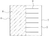
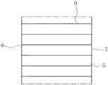
図2は、図1に示すタイヤ1のビードベース面5を矢視A(ビードコア2からビードベース面5に延びる垂線に沿う方向)から見た平面図である。ビードベース面5は、タイヤ周方向につながった内周面で構成された、ビードトウ6からビードヒール7までの領域である。ビードベース面5は、何も形成されていない内側領域8(図2中、2点鎖線で示す。)と、それ以外の複数の凹部すなわち溝部9が形成された外側領域10とで構成されている。
FIG. 2 is a plan view of the
内側領域8は、平坦面であり、リム3の当接受面4に面接触できるように構成されている。ここで、ビードトウ6からビードヒール7までの長さをビードベース幅BWと定義すると、内側領域8の形成範囲は、ビードトウ6からビードベース幅BWの5%以上15%以下の長さの範囲とするのが好ましい。これによれば、リム3の当接受面4に対してタイヤ幅方向に十分な長さを有する内側領域8を面接触させることができる。したがって、この接触領域によってタイヤ1の内部からの空気漏れを確実に防止することが可能となる。また、後述する溝部9の形成範囲が狭くなってリムずれ防止効果が損なわれるといったこともない。
The
この場合、内側領域8は、ビードベース面5を矢視Aから透視(平面投影視)してビードコア2と重ならない位置とするのが好ましい。これによれば、ビードコア下部は、リムに対して圧力が高くなる位置のため、重ならないほうがリムずれ防止効果が損なわれない。
In this case, it is preferable that the
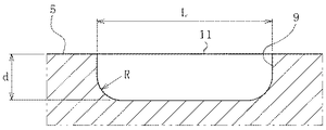
ビードベース面5には、複数の溝部9が形成されている。溝部9はタイヤ幅方向に延びる直線状で、図3に示すように、両端では溝底側が半径Rの円弧状に形成されている。各溝部9は、ビードベース面5の表面からの溝深さD、溝幅W、タイヤ周方向の溝間隔Pを自由に設定できる。但し、溝幅Wは溝長さLに比べて十分に小さく、ビードベース面5に圧接されることにより、溝幅が0となるように形成されているのが好ましい。そして、溝部9を形成することによって得られたエッジ部11は、リム3の当接受面4に圧接してずれを防止する機能を発揮するようにすればよい。また溝部9は、図2、図4、図5及び図6に示す種々のパターンで形成できる。
A plurality of
図2では、内側領域8をビードトウ6からビードベース幅BWの5%以上15%以下である10%の長さの範囲としている。
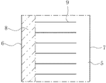
図4では、内側領域8をビードトウ6からビードベース幅BWの50%の長さの範囲としている。
図5では、内側領域8をビードトウ6からビードベース幅BWの20%の長さの範囲としている。また、外側領域10にもビードヒール7から内側に、ビードベース幅BWの20%の長さの範囲を溝部9が形成されていない領域としている。
図6では、溝部9をビードトウ6からビードヒール7までビードベース面5を横切るように形成している。つまり、内側領域8は形成されていない。
In FIG. 2, the
In FIG. 4, the
In FIG. 5, the
In FIG. 6, the
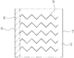
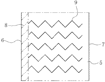
溝部9は、直線状に限らず、図7に示すような鋸歯状としたり、図示しないが、波形としたりする等、エッジ部11の長さを長くすることができる種々の形状とすることもできる。これによれば、溝部9によって形成されるエッジ部11の長さを長くして、タイヤ周方向へのリムずれ防止効果を高めることができる。また、タイヤ周方向以外へのリム3に対するタイヤ1の位置ずれを抑制してリム外れを防止する効果もある。
The
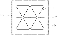
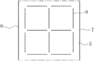
溝部9は、タイヤ幅方向に沿って平行に形成するようにしたが、多角形を構成するように形成してもよい。例えば、図8に示す三角形、図9に示す四角形、図10に示す六角形等で形成することができる。この場合、各辺を構成する溝部9は互いに連通しないように形成するのが好ましい。これによれば、リム3に対するタイヤ1のずれ防止を、タイヤ周方向だけでなく、種々の方向に対して発揮することができる。
The
このように、溝部9を多角形に配置することで、路面からタイヤ1に作用する種々の方向からの力に対して、溝部9を構成するエッジ部11が有効に作用し、リム3の当接受面4に対する位置ずれを効果的に防止することができる。
Thus, by arranging the
比較例及び実施例に係るタイヤ1について、リムずれ防止性能及びエア漏れ防止性能をそれぞれ比較例の場合を100として指数により評価した。
リムずれ防止性能については、速度50km/hで制動試験を10回繰り返し、リム3に対するタイヤ1のずれ量を測定した結果を評価した。
エア漏れ防止性能については、リム組み後、一定温度の室温で90日、静的放置し、内圧の低下状態を評価した。
About the
Regarding the rim displacement prevention performance, the braking test was repeated 10 times at a speed of 50 km / h, and the result of measuring the displacement amount of the
Regarding air leakage prevention performance, after assembling the rim, it was left statically at room temperature for 90 days to evaluate the reduced internal pressure.
溝部9のレイアウトは、実施例1〜4については図2、実施例5については図4、実施例6については図5とした。溝深さは実施例2を0.4mmとし、他は1.0mmとした。溝幅は実施例3を2.0mmとし、他は1.0mmとした。溝間隔は、実施例4を5.0mmとし、他は3.0mmとした。
The layout of the
このように、溝深さを1.0mmとすることで、リム3の当接受面4に対するエッジ部11の変形度合いを最も適切なものとして位置ずれを効果的に防止することができた。溝深さは、0.4mm〜1.0mmの範囲とすることで、リムずれの防止効果が期待できる。また、溝幅及び溝間隔を大きくすればする程、リムずれ防止性能が悪化する。溝幅2.0mm以下、溝間隔5.0mm以下とすることでも、リムずれ防止効果が期待できる。 As described above, by setting the groove depth to 1.0 mm, the degree of deformation of the edge portion 11 with respect to the abutment receiving surface 4 of the rim 3 can be made the most appropriate and displacement can be effectively prevented. By setting the groove depth in the range of 0.4 mm to 1.0 mm, an effect of preventing rim displacement can be expected. In addition, the rim displacement prevention performance deteriorates as the groove width and the groove interval are increased. Even when the groove width is 2.0 mm or less and the groove interval is 5.0 mm or less, the effect of preventing rim displacement can be expected.
なお、本発明は、前記実施形態に記載された構成に限定されるものではなく、種々の変更が可能である。 In addition, this invention is not limited to the structure described in the said embodiment, A various change is possible.
前記実施形態では、リムずれ防止部の凹部の例として溝部9の異なる形態について説明したが、このリムずれ防止部は凹部に限らず、凸部で構成することもできる。例えば、前記各実施形態について凹部に代えて凸部を採用することで、凸部のエッジ部分がリム3の当接受面4に作用してリム3に対するタイヤ1の位置ずれを効果的に防止することができる。
In the above-described embodiment, the different forms of the
1…タイヤ
2…ビードコア
3…リム
4…当接受面
5…ビードベース面
6…ビードトウ
7…ビードヒール
8…内側領域
9…溝部
10…外側領域
11…エッジ部
DESCRIPTION OF
Claims (5)
Priority Applications (1)
| Application Number | Priority Date | Filing Date | Title |
|---|---|---|---|
| JP2016235341A JP6826422B2 (en) | 2016-12-02 | 2016-12-02 | Pneumatic tires |
Applications Claiming Priority (1)
| Application Number | Priority Date | Filing Date | Title |
|---|---|---|---|
| JP2016235341A JP6826422B2 (en) | 2016-12-02 | 2016-12-02 | Pneumatic tires |
Publications (2)
| Publication Number | Publication Date |
|---|---|
| JP2018090102A true JP2018090102A (en) | 2018-06-14 |
| JP6826422B2 JP6826422B2 (en) | 2021-02-03 |
Family
ID=62564132
Family Applications (1)
| Application Number | Title | Priority Date | Filing Date |
|---|---|---|---|
| JP2016235341A Active JP6826422B2 (en) | 2016-12-02 | 2016-12-02 | Pneumatic tires |
Country Status (1)
| Country | Link |
|---|---|
| JP (1) | JP6826422B2 (en) |
Citations (4)
| Publication number | Priority date | Publication date | Assignee | Title |
|---|---|---|---|---|
| JPS5441002U (en) * | 1977-08-05 | 1979-03-19 | ||
| JPH03169727A (en) * | 1989-11-30 | 1991-07-23 | Sumitomo Rubber Ind Ltd | Tubeless tire |
| JPH06127221A (en) * | 1992-10-16 | 1994-05-10 | Yokohama Rubber Co Ltd:The | Pneumatic tire |
| CN106114074A (en) * | 2016-08-27 | 2016-11-16 | 厦门正新橡胶工业有限公司 | Tire bead structure |
-
2016
- 2016-12-02 JP JP2016235341A patent/JP6826422B2/en active Active
Patent Citations (4)
| Publication number | Priority date | Publication date | Assignee | Title |
|---|---|---|---|---|
| JPS5441002U (en) * | 1977-08-05 | 1979-03-19 | ||
| JPH03169727A (en) * | 1989-11-30 | 1991-07-23 | Sumitomo Rubber Ind Ltd | Tubeless tire |
| JPH06127221A (en) * | 1992-10-16 | 1994-05-10 | Yokohama Rubber Co Ltd:The | Pneumatic tire |
| CN106114074A (en) * | 2016-08-27 | 2016-11-16 | 厦门正新橡胶工业有限公司 | Tire bead structure |
Also Published As
| Publication number | Publication date |
|---|---|
| JP6826422B2 (en) | 2021-02-03 |
Similar Documents
| Publication | Publication Date | Title |
|---|---|---|
| JP5599814B2 (en) | Tire tread with incision with protrusion | |
| US10464377B2 (en) | Winter tire | |
| JP2015214327A (en) | Pneumatic tire for vehicle | |
| JP6434279B2 (en) | Pneumatic tire | |
| JP6517598B2 (en) | Pneumatic tire | |
| JP5526266B1 (en) | Pneumatic tire | |
| CN105922823B (en) | Pneumatic tire | |
| CN109421438B (en) | Pneumatic tires | |
| JP6228001B2 (en) | Pneumatic tire and manufacturing method thereof | |
| JP6198577B2 (en) | Pneumatic tire | |
| JP2018090102A (en) | Pneumatic tire | |
| JP5851275B2 (en) | Pneumatic tire | |
| JP5801133B2 (en) | Pneumatic tire | |
| CN106240243B (en) | Pneumatic tire | |
| JP6294628B2 (en) | Pneumatic tire | |
| JP2013220716A (en) | Pneumatic tire | |
| JP2019099077A (en) | Pneumatic tire | |
| JP6932497B2 (en) | Pneumatic tires | |
| JP6174982B2 (en) | Pneumatic tire | |
| JPH04176712A (en) | Pneumatic tire | |
| JP2019064591A (en) | Pneumatic tire | |
| US11685196B2 (en) | Pneumatic tire | |
| JP2005297845A (en) | Pneumatic tire | |
| JP6207911B2 (en) | Pneumatic tire rim | |
| JP6986420B2 (en) | Pneumatic tires |
Legal Events
| Date | Code | Title | Description |
|---|---|---|---|
| A621 | Written request for application examination |
Free format text: JAPANESE INTERMEDIATE CODE: A621 Effective date: 20191028 |
|
| A977 | Report on retrieval |
Free format text: JAPANESE INTERMEDIATE CODE: A971007 Effective date: 20200907 |
|
| A131 | Notification of reasons for refusal |
Free format text: JAPANESE INTERMEDIATE CODE: A131 Effective date: 20200915 |
|
| A521 | Request for written amendment filed |
Free format text: JAPANESE INTERMEDIATE CODE: A523 Effective date: 20201030 |
|
| TRDD | Decision of grant or rejection written | ||
| A01 | Written decision to grant a patent or to grant a registration (utility model) |
Free format text: JAPANESE INTERMEDIATE CODE: A01 Effective date: 20210112 |
|
| A61 | First payment of annual fees (during grant procedure) |
Free format text: JAPANESE INTERMEDIATE CODE: A61 Effective date: 20210115 |
|
| R150 | Certificate of patent or registration of utility model |
Ref document number: 6826422 Country of ref document: JP Free format text: JAPANESE INTERMEDIATE CODE: R150 |
|
| R250 | Receipt of annual fees |
Free format text: JAPANESE INTERMEDIATE CODE: R250 |
|
| R250 | Receipt of annual fees |
Free format text: JAPANESE INTERMEDIATE CODE: R250 |
|
| R250 | Receipt of annual fees |
Free format text: JAPANESE INTERMEDIATE CODE: R250 |