JP2018105228A - ベーン型圧縮機の給油構造 - Google Patents
ベーン型圧縮機の給油構造 Download PDFInfo
- Publication number
- JP2018105228A JP2018105228A JP2016252323A JP2016252323A JP2018105228A JP 2018105228 A JP2018105228 A JP 2018105228A JP 2016252323 A JP2016252323 A JP 2016252323A JP 2016252323 A JP2016252323 A JP 2016252323A JP 2018105228 A JP2018105228 A JP 2018105228A
- Authority
- JP
- Japan
- Prior art keywords
- oil supply
- back pressure
- rotor
- oil
- vane
- Prior art date
- Legal status (The legal status is an assumption and is not a legal conclusion. Google has not performed a legal analysis and makes no representation as to the accuracy of the status listed.)
- Granted
Links
- 238000003860 storage Methods 0.000 claims abstract description 30
- 238000004891 communication Methods 0.000 claims description 44
- 238000007906 compression Methods 0.000 claims description 23
- 230000006835 compression Effects 0.000 claims description 22
- 230000002093 peripheral effect Effects 0.000 claims description 17
- 239000012530 fluid Substances 0.000 claims description 10
- 238000010276 construction Methods 0.000 claims 1
- 239000003921 oil Substances 0.000 description 147
- 238000000926 separation method Methods 0.000 description 13
- 244000145845 chattering Species 0.000 description 4
- 238000010586 diagram Methods 0.000 description 4
- 239000010687 lubricating oil Substances 0.000 description 4
- 238000005057 refrigeration Methods 0.000 description 4
- 230000004323 axial length Effects 0.000 description 3
- 238000005461 lubrication Methods 0.000 description 3
- 238000012545 processing Methods 0.000 description 3
- 239000003507 refrigerant Substances 0.000 description 3
- 230000007423 decrease Effects 0.000 description 2
- 230000000694 effects Effects 0.000 description 2
- 238000000034 method Methods 0.000 description 2
- 238000012986 modification Methods 0.000 description 2
- 230000004048 modification Effects 0.000 description 2
- 238000007789 sealing Methods 0.000 description 2
- 230000002238 attenuated effect Effects 0.000 description 1
- 230000006837 decompression Effects 0.000 description 1
- 238000007599 discharging Methods 0.000 description 1
- 238000005553 drilling Methods 0.000 description 1
- 238000003780 insertion Methods 0.000 description 1
- 230000037431 insertion Effects 0.000 description 1
- 238000004519 manufacturing process Methods 0.000 description 1
- 230000000149 penetrating effect Effects 0.000 description 1
- 238000003825 pressing Methods 0.000 description 1
- 230000001603 reducing effect Effects 0.000 description 1
- 230000001629 suppression Effects 0.000 description 1
Images





Classifications
-
- F—MECHANICAL ENGINEERING; LIGHTING; HEATING; WEAPONS; BLASTING
- F04—POSITIVE - DISPLACEMENT MACHINES FOR LIQUIDS; PUMPS FOR LIQUIDS OR ELASTIC FLUIDS
- F04C—ROTARY-PISTON, OR OSCILLATING-PISTON, POSITIVE-DISPLACEMENT MACHINES FOR LIQUIDS; ROTARY-PISTON, OR OSCILLATING-PISTON, POSITIVE-DISPLACEMENT PUMPS
- F04C18/00—Rotary-piston pumps specially adapted for elastic fluids
- F04C18/30—Rotary-piston pumps specially adapted for elastic fluids having the characteristics covered by two or more of groups F04C18/02, F04C18/08, F04C18/22, F04C18/24, F04C18/48, or having the characteristics covered by one of these groups together with some other type of movement between co-operating members
- F04C18/34—Rotary-piston pumps specially adapted for elastic fluids having the characteristics covered by two or more of groups F04C18/02, F04C18/08, F04C18/22, F04C18/24, F04C18/48, or having the characteristics covered by one of these groups together with some other type of movement between co-operating members having the movement defined in group F04C18/08 or F04C18/22 and relative reciprocation between the co-operating members
- F04C18/344—Rotary-piston pumps specially adapted for elastic fluids having the characteristics covered by two or more of groups F04C18/02, F04C18/08, F04C18/22, F04C18/24, F04C18/48, or having the characteristics covered by one of these groups together with some other type of movement between co-operating members having the movement defined in group F04C18/08 or F04C18/22 and relative reciprocation between the co-operating members with vanes reciprocating with respect to the inner member
-
- F—MECHANICAL ENGINEERING; LIGHTING; HEATING; WEAPONS; BLASTING
- F04—POSITIVE - DISPLACEMENT MACHINES FOR LIQUIDS; PUMPS FOR LIQUIDS OR ELASTIC FLUIDS
- F04C—ROTARY-PISTON, OR OSCILLATING-PISTON, POSITIVE-DISPLACEMENT MACHINES FOR LIQUIDS; ROTARY-PISTON, OR OSCILLATING-PISTON, POSITIVE-DISPLACEMENT PUMPS
- F04C29/00—Component parts, details or accessories of pumps or pumping installations, not provided for in groups F04C18/00 - F04C28/00
- F04C29/02—Lubrication; Lubricant separation
Landscapes
- Engineering & Computer Science (AREA)
- Mechanical Engineering (AREA)
- General Engineering & Computer Science (AREA)
- Rotary Pumps (AREA)
Abstract
Description
このようにオイル供給通路にオリフィスを設けることで、背圧室に供給される圧力が適切に低減され、ベーンが過大な力でカム面に押し付けられることを回避でき、ベーンやカム面の破損を防ぐことが可能となる。
また、オイルに混入する異物がオリフィスに詰まり、背圧室に導かれるオイル量が減少して所定の背圧が得られなくなり、ベーンが適切にカム面に押し付けられずにチャタリングを引き起こす恐れもある。
また、スラストクリアランスは、各部品の製造誤差によりばらついてしまうため、適切な圧力に減衰するように管理することは困難である。
このような構成においては、間欠間隔を調整することで背圧導入凹部へのオイル供給を調節できるので、適切な背圧室の圧力を維持するよう設定することが可能となる。
このような構成によれば、連通凹部の巾を調整することで、ロータの端面に形成された接続溝と連通凹部との連通時間が調節可能となるので、背圧導入凹部へのオイル供給量(背圧室の圧力)を容易に調節することが可能となる。
このような構成においては、上述した作用に加え、接続溝をオイルで満たした後に径方向溝部を連通凹部と連通させて接続溝内のオイルを背圧導入凹部に供給することが可能となるので、背圧導入凹部へオイル供給を確実に行うことが可能となる。
このような構成においては、周方向溝部の長さを調節することで、周方向溝部がオイル供給通路の開口部と連通する時間を調節できるので、背圧導入凹部へのオイル供給量(背圧室の圧力)および背圧導入凹部の圧力を容易に調節することが可能となる。
したがって、前記圧縮空間11は、ベーン6によって複数の圧縮室13に仕切られ、それぞれの圧縮室13の容積は、ベーン6がロータ4の回転に伴い孔10の長径部から短径部へ進行すると徐々に減少し、この圧縮室13内の作動流体を圧縮するようになっている。
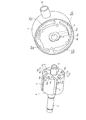
シリンダ2の軸方向長さは、ロータ4およびベーン6の軸方向長さより僅かに大きくなるよう形成されており、これにより、シリンダ2がフロント側サイドブロック8およびリア側サイドブロック7に当接しても、シリンダ2の楕円形の孔10内に収容されたロータ4およびベーン6は、両サイドブロック間において所定のスラストクリアランスを有して保持され、両サイドブロックに挟持されることなく回転できるようになっている。
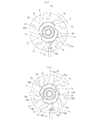
この例においては、リア側サイドブロック7のロータ4の端面と対峙する面には、背圧導入凹部71から径方向外側へ延設された所定巾の連通凹部71aを設け、この連通凹部71aに前記接続溝73の径方向溝部73bが、ロータ4の回転に伴い間欠的に連通するようになっている。
したがって、オイル供給通路72にオリフィスを設ける必要がなく、また、背圧導入凹部71に至るまでの経路が絞られ過ぎてオイル供給が不十分になる不都合もなくなり、背圧室5aの圧力がチャタリング抑制に必要な値より低くなる不都合を回避することが可能となる。
このような構成においては、背圧導入凹部71へのオイル供給量および背圧導入凹部の圧力を周方向溝部73aの長さのみを調節することで調節可能となる。
2 シリンダ
3 駆動軸
4 ロータ
5 ベーン溝
5a 背圧室
6 ベーン
7 リア側サイドブロック
8 フロント側サイドブロック
35 貯油室
71 背圧導入凹部
71a 連通凹部
72 オイル供給通路
73 接続溝
73a 周方向溝部
73b 径方向溝部
Claims (5)
- 内周面にカム面が形成されたシリンダと、
前記シリンダの軸方向の両端を閉塞する一対のサイドブロックと、
前記一対のサイドブロックに回転自在に支持された駆動軸と、
前記駆動軸に固装されて前記シリンダ内に回転可能に収容されるロータと、
前記ロータに形成された複数のベーン溝と、
前記ベーン溝に摺動自在に挿入され、先端部が前記ベーン溝から出没して前記カム面を摺動する複数のベーンと、
前記ベーン溝の底部に前記ベーンによって区画された背圧室と、
前記シリンダと前記一対のサイドブロックとにより閉塞された空間に、前記ロータと前記ベーンとによって画成される圧縮室と、
前記圧縮室から吐出された流体を収容する吐出圧力領域と、
前記吐出圧力領域の一部を構成し、前記吐出された流体から分離されたオイルを貯留する貯油室と、を備え、
前記一対のサイドブロックの前記ロータの端面と対峙する面に、前記背圧室と連通可能な背圧導入凹部を形成し、
前記背圧導入凹部の少なくとも一方に前記貯油室に貯留されているオイルをオイル供給通路を介して供給するベーン型圧縮機の給油構造において、
前記オイル供給通路を前記ロータの端面と対峙する前記サイドブロックの端面に開口し、このオイル供給通路の前記サイドブロックの端面に形成された開口部を前記ロータの端面に形成された接続溝を介して前記背圧導入凹部と連通可能にしたことを特徴とするベーン型圧縮機の給油構造。 - 前記オイル供給通路の開口部と前記背圧導入凹部とは、前記ロータの回転に伴い前記接続溝を介して間欠的に連通されることを特徴とする請求項1記載のベーン型圧縮機の給油構造。
- 前記サイドブロックの前記ロータの端面と対峙する面には、前記背圧導入凹部から径方向外側へ延設された所定巾の連通凹部が形成され、前記接続溝は、前記オイル供給通路の開口部と前記連通凹部とを間欠的に連通させるものであることを特徴とする請求項2記載のベーン型圧縮機の給油構造。
- 前記接続溝は、前記オイル供給通路の開口部を過ぎるように周方向に延設された周方向溝部と、この周方向溝部の回転方向後端部から径方向に延設し、前記連通凹部と間欠的に連通する径方向溝部とを有して構成されていることを特徴とする請求項3記載のベーン型圧縮機の給油構造。
- 前記接続溝は、前記オイル供給通路の開口部を過ぎるように周方向に延設された周方向溝部と、この周方向溝部の回転方向後端部から径方向に延設し、前記背圧導入凹部に連通する径方向溝部とを有して構成されていることを特徴とする請求項2記載のベーン型圧縮機の給油構造。
Priority Applications (2)
| Application Number | Priority Date | Filing Date | Title |
|---|---|---|---|
| JP2016252323A JP6760836B2 (ja) | 2016-12-27 | 2016-12-27 | ベーン型圧縮機の給油構造 |
| PCT/JP2017/046117 WO2018123860A1 (ja) | 2016-12-27 | 2017-12-22 | ベーン型圧縮機の給油構造 |
Applications Claiming Priority (1)
| Application Number | Priority Date | Filing Date | Title |
|---|---|---|---|
| JP2016252323A JP6760836B2 (ja) | 2016-12-27 | 2016-12-27 | ベーン型圧縮機の給油構造 |
Publications (2)
| Publication Number | Publication Date |
|---|---|
| JP2018105228A true JP2018105228A (ja) | 2018-07-05 |
| JP6760836B2 JP6760836B2 (ja) | 2020-09-23 |
Family
ID=62708185
Family Applications (1)
| Application Number | Title | Priority Date | Filing Date |
|---|---|---|---|
| JP2016252323A Active JP6760836B2 (ja) | 2016-12-27 | 2016-12-27 | ベーン型圧縮機の給油構造 |
Country Status (2)
| Country | Link |
|---|---|
| JP (1) | JP6760836B2 (ja) |
| WO (1) | WO2018123860A1 (ja) |
Cited By (2)
| Publication number | Priority date | Publication date | Assignee | Title |
|---|---|---|---|---|
| WO2020179652A1 (ja) * | 2019-03-06 | 2020-09-10 | 株式会社豊田自動織機 | 圧縮機 |
| US12152584B2 (en) | 2020-06-29 | 2024-11-26 | Gree Electric Appliances, Inc. Of Zhuhai | Flange and pump body assembly with same |
Families Citing this family (1)
| Publication number | Priority date | Publication date | Assignee | Title |
|---|---|---|---|---|
| KR102538954B1 (ko) * | 2021-11-30 | 2023-06-02 | 엘지전자 주식회사 | 로터리 압축기 |
Family Cites Families (2)
| Publication number | Priority date | Publication date | Assignee | Title |
|---|---|---|---|---|
| JP2964193B2 (ja) * | 1992-02-07 | 1999-10-18 | 株式会社ゼクセル | ベーン型圧縮機 |
| CN107002677A (zh) * | 2014-11-28 | 2017-08-01 | 株式会社丰田自动织机 | 叶片型压缩机 |
-
2016
- 2016-12-27 JP JP2016252323A patent/JP6760836B2/ja active Active
-
2017
- 2017-12-22 WO PCT/JP2017/046117 patent/WO2018123860A1/ja not_active Ceased
Cited By (2)
| Publication number | Priority date | Publication date | Assignee | Title |
|---|---|---|---|---|
| WO2020179652A1 (ja) * | 2019-03-06 | 2020-09-10 | 株式会社豊田自動織機 | 圧縮機 |
| US12152584B2 (en) | 2020-06-29 | 2024-11-26 | Gree Electric Appliances, Inc. Of Zhuhai | Flange and pump body assembly with same |
Also Published As
| Publication number | Publication date |
|---|---|
| WO2018123860A1 (ja) | 2018-07-05 |
| JP6760836B2 (ja) | 2020-09-23 |
Similar Documents
| Publication | Publication Date | Title |
|---|---|---|
| EP2520803B1 (en) | Compressor | |
| JP5765379B2 (ja) | スクロール圧縮機 | |
| EP3754199B1 (en) | Scroll compressor | |
| KR101099923B1 (ko) | 스크롤형 압축기 | |
| US9388807B2 (en) | Vane compressor having a second discharge port that includes an opening portion to a compression space | |
| KR101519698B1 (ko) | 베인 로터리 압축기 | |
| JP2014177887A (ja) | スクリュー圧縮機 | |
| JP5366884B2 (ja) | ベーンロータリー型圧縮機 | |
| WO2018123860A1 (ja) | ベーン型圧縮機の給油構造 | |
| KR100937919B1 (ko) | 오일순환 및 배압조절 기능이 개선된 스크롤 압축기 | |
| JP6238726B2 (ja) | 圧縮機 | |
| WO2016190380A1 (ja) | 圧縮機 | |
| WO2016189801A1 (ja) | シリンダ回転型圧縮機 | |
| JP6130271B2 (ja) | スクロール圧縮機 | |
| JP6156158B2 (ja) | ベーン型圧縮機 | |
| KR102138856B1 (ko) | 스크롤 압축기 | |
| JP4043233B2 (ja) | 気体圧縮機 | |
| JP4421359B2 (ja) | 気体圧縮機 | |
| WO2017217523A1 (ja) | 圧縮機 | |
| JP4185723B2 (ja) | 気体圧縮機 | |
| JP2006241993A (ja) | スクロール型圧縮機 | |
| KR102031851B1 (ko) | 전동식 압축기 | |
| KR20170040409A (ko) | 베인 로터리 압축기 | |
| WO2017163829A1 (ja) | スクロール圧縮機 | |
| JP5878971B1 (ja) | 気体圧縮機 |
Legal Events
| Date | Code | Title | Description |
|---|---|---|---|
| A621 | Written request for application examination |
Free format text: JAPANESE INTERMEDIATE CODE: A621 Effective date: 20191205 |
|
| A131 | Notification of reasons for refusal |
Free format text: JAPANESE INTERMEDIATE CODE: A131 Effective date: 20200604 |
|
| A521 | Request for written amendment filed |
Free format text: JAPANESE INTERMEDIATE CODE: A523 Effective date: 20200728 |
|
| TRDD | Decision of grant or rejection written | ||
| A01 | Written decision to grant a patent or to grant a registration (utility model) |
Free format text: JAPANESE INTERMEDIATE CODE: A01 Effective date: 20200812 |
|
| A61 | First payment of annual fees (during grant procedure) |
Free format text: JAPANESE INTERMEDIATE CODE: A61 Effective date: 20200903 |
|
| R150 | Certificate of patent or registration of utility model |
Ref document number: 6760836 Country of ref document: JP Free format text: JAPANESE INTERMEDIATE CODE: R150 |
|
| R250 | Receipt of annual fees |
Free format text: JAPANESE INTERMEDIATE CODE: R250 |