JP2018188773A - 筬 - Google Patents
筬 Download PDFInfo
- Publication number
- JP2018188773A JP2018188773A JP2017093268A JP2017093268A JP2018188773A JP 2018188773 A JP2018188773 A JP 2018188773A JP 2017093268 A JP2017093268 A JP 2017093268A JP 2017093268 A JP2017093268 A JP 2017093268A JP 2018188773 A JP2018188773 A JP 2018188773A
- Authority
- JP
- Japan
- Prior art keywords
- plating layer
- particles
- wing
- wings
- wear
- Prior art date
- Legal status (The legal status is an assumption and is not a legal conclusion. Google has not performed a legal analysis and makes no representation as to the accuracy of the status listed.)
- Granted
Links
Images
Landscapes
- Looms (AREA)
Abstract
Description
本発明は、織機に利用される筬に関する。 The present invention relates to a kite used in a loom.
従来、織機には、タテ糸の配置間隔などを揃えて整列させるための筬が用いられている。例えば、特許文献1には、ステンレス製の複数の筬羽を備える筬が開示されている。
2. Description of the Related Art Conventionally, a loom has been used for looms for aligning warp yarns at regular intervals. For example,
しかしながら、上記従来のステンレス製の筬では、ステンレス線を用いた金属メッシュを製造する場合に、筬羽が摩耗するという問題がある。摩耗により筬羽に凹凸が形成されることで、製織中にタテ糸の断線が発生する。 However, the conventional stainless steel kite has a problem that the kite wing is worn when a metal mesh using a stainless steel wire is manufactured. By forming irregularities on the wings due to wear, the warp yarn breaks during weaving.
そこで、本発明は、耐摩耗性に優れた筬を提供することを目的とする。 Then, an object of this invention is to provide the wrinkles excellent in abrasion resistance.
上記目的を達成するため、本発明の一態様に係る筬は、織機に利用される筬であって、間隔を空けて並んで配置された複数の筬羽と、前記複数の筬羽を支持する支持体とを備え、前記複数の筬羽の各々は、金属製の基材と、前記基材の表面に設けられためっき層と、前記めっき層内に分散された複数の粒子とを備える。 In order to achieve the above object, a kite according to one embodiment of the present invention is a kite used in a loom, and supports a plurality of kite feathers arranged side by side at intervals, and the plurality of kite feathers Each of the plurality of wings includes a metal base, a plating layer provided on the surface of the base, and a plurality of particles dispersed in the plating layer.
本発明によれば、耐摩耗性に優れた筬を提供することができる。 According to the present invention, it is possible to provide a ridge excellent in wear resistance.
以下では、本発明の実施の形態に係る筬について、図面を用いて詳細に説明する。なお、以下に説明する実施の形態は、いずれも本発明の一具体例を示すものである。したがって、以下の実施の形態で示される数値、形状、材料、構成要素、構成要素の配置及び接続形態、ステップ、ステップの順序などは、一例であり、本発明を限定する趣旨ではない。よって、以下の実施の形態における構成要素のうち、本発明の最上位概念を示す独立請求項に記載されていない構成要素については、任意の構成要素として説明される。 Hereinafter, the bag according to the embodiment of the present invention will be described in detail with reference to the drawings. Each of the embodiments described below shows a specific example of the present invention. Therefore, numerical values, shapes, materials, components, arrangement and connection forms of components, steps, order of steps, and the like shown in the following embodiments are merely examples, and are not intended to limit the present invention. Therefore, among the constituent elements in the following embodiments, constituent elements that are not described in the independent claims showing the highest concept of the present invention are described as optional constituent elements.
また、各図は、模式図であり、必ずしも厳密に図示されたものではない。したがって、例えば、各図において縮尺などは必ずしも一致しない。また、各図において、実質的に同一の構成については同一の符号を付しており、重複する説明は省略又は簡略化する。 Each figure is a mimetic diagram and is not necessarily illustrated strictly. Therefore, for example, the scales and the like do not necessarily match in each drawing. Moreover, in each figure, the same code | symbol is attached | subjected about the substantially same structure, The overlapping description is abbreviate | omitted or simplified.
また、本明細書において、平行などの要素間の関係性を示す用語、及び、要素の形状を示す用語、並びに、数値範囲は、厳格な意味のみを表す表現ではなく、実質的に同等な範囲、例えば数%程度の差異をも含むことを意味する表現である。 Further, in this specification, terms indicating the relationship between elements such as parallel, terms indicating the shape of elements, and numerical ranges are not equivalent expressions only, but are substantially equivalent ranges. For example, it is an expression meaning that a difference of about several percent is included.
(実施の形態)
[構成]
まず、本実施の形態に係る筬の構成について、図1〜図3を用いて説明する。
(Embodiment)
[Constitution]
First, the configuration of the bag according to the present embodiment will be described with reference to FIGS.
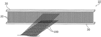
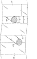
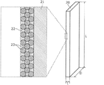
図1は、本実施の形態に係る筬10の斜視図である。図2は、本実施の形態に係る筬10の筬羽20と、隣り合う筬羽20の間に通された金属線100とを拡大して示す拡大斜視図である。図3は、本実施の形態に係る筬10の筬羽20の外観と筬羽20の表面の断面構造とを示す図である。なお、図3では、筬羽20の表面の断面構造を拡大して示している。
FIG. 1 is a perspective view of a
本実施の形態では、筬10は、織機に利用される。具体的には、筬10は、複数の金属線100の製織を行う織機に利用される。織機は、例えば、複数の金属線100の製織を行うことで、スクリーン印刷用のスクリーンメッシュなどの金属メッシュを製造する。
In the present embodiment, the
なお、金属線100は、例えば、ステンレス(SUS)、又は、タングステン(W)若しくはタングステン合金からなる細線である。金属線100がタングステン若しくはタングステン合金からなる場合、金属線100の線径φは、例えば60μm以下であり、一例として、13μmである。
The
図1に示すように、筬10は、複数の筬羽20と、支持体30とを備える。
As shown in FIG. 1, the
複数の筬羽20は、間隔を空けて並んで配置されている。複数の筬羽20の各々は、図3に示すように、細長い矩形板状の部材である。複数の筬羽20の各々は、互いに同じ構成を有する。筬羽20の長さLは、例えば50mmであり、奥行きDは、例えば10mmであり、厚みtは、例えば40μmである。なお、筬羽20の寸法は一例に過ぎず、これらに限定されない。
The plurality of
複数の筬羽20は、筬羽20の厚み方向に並んで、間隔を空けて平行に配置されている。例えば、図2に示すように、複数の筬羽20は、所定の間隔P毎に等間隔で並んで配置されている。隣り合う筬羽20の間に、1本の金属線100が通されている。間隔Pは、例えば15μmであるが、これに限らない。間隔Pは、金属線100の線形φ及び製織後の織物(メッシュ)の目開きなどに応じて適宜定められる。
The plurality of
ここで、複数の金属線100は、製織が行われる際に、筬羽20の間で上下方向への移動を繰り返す。なお、上下方向とは、筬羽20の長手方向であり、図3の長さLに沿った方向である。図2に示すように、金属線100と筬羽20との間の隙間は、例えば1μmであり、非常に狭い。このため、金属線100の上下方向の移動によって、金属線100と筬羽20とが擦れ合い、筬羽20の摩耗の原因となる。また、金属メッシュの横糸(図示せず)を打ち込む際、あるいは、縦糸の金属線100の送り出しの際にも筬羽20と金属線100とが擦れ合い、筬羽20の磨耗の原因となる。
Here, the plurality of
本実施の形態では、図3に示すように、筬羽20は、基材21と、めっき層22と、複数の粒子23とを備える。
In the present embodiment, as shown in FIG. 3, the
基材21は、金属製である。具体的には、基材21は、炭素工具鋼鋼材から構成されている。例えば、基材21は、JIS規格で定められるSK120(旧JIS規格のSK2)又はSK105(同、SK3)などから構成されている。あるいは、基材21は、ステンレス、タングステン又はモリブデン(Mo)及びそれらの合金などから構成されていてもよい。
The
基材21は、例えば、所定の板厚(厚みt)、かつ、所定の幅(奥行きD)の細長いリール状の金属帯を、所定の長さ(長さL)毎に切断することで形成される。なお、この切断は、リール状の金属帯の表面にめっき層22を形成した後に行われてもよい。したがって、例えば、切断面である基材21の長手方向の端面には、めっき層22が形成されていなくてもよい。
The
めっき層22は、基材21の表面に設けられている。めっき層22は、基材21の全表面に設けられているが、これに限らない。例えば、めっき層22は、基材21の主面(具体的には、厚み方向に交差する面)のみに設けられていてもよい。めっき層22の厚みは、面内において均一であり、例えば1μm以上5μm以下である。
The
めっき層22は、例えば、ニッケル(Ni)を主成分として含有する。具体的には、めっき層22は、ニッケルから構成される金属めっき層であるが、これに限らない。例えば、めっき層22は、ニッケル−リン(Ni−P)又はニッケル−タングステン−リン(Ni−W−P)の合金めっき層でもよい。あるいは、めっき層22は、クロム(Cr)から構成される金属めっき層でもよい。
The
めっき層22は、基材21(又は、基材21の元になるリール状の金属帯)とニッケル板とをめっき液に浸した状態で、基材21(又は金属帯)とニッケル板との間に通電することで形成される。なお、めっき液は、例えば、硫酸ニッケル、塩化ニッケル及びホウ酸を含む液体である。めっき液には、複数の粒子23が分散されている。これにより、基材21の表面に、複数の粒子23が分散されためっき層22が形成される。なお、めっき層22の形成後に、熱処理を加えてもよい。これにより、筬羽20の耐摩耗性を高めることができる。詳細については、図8を用いて後で説明する。上記は、電解めっきによる方法の説明であるが、通電しない無電解めっきでも同様にめっきが形成できる。
The
複数の粒子23は、めっき層22内に分散されている。複数の粒子23の平均粒径は、ナノオーダーであり、1μmより小さい。粒子23は、例えば、ナノダイヤモンド粒子である。ナノダイヤモンドは、硬度が高く、かつ、摩擦係数が低い。したがって、筬羽20の硬度を高め、かつ、筬羽20の表面の滑りを良くすることができる。なお、粒子23は、セラミックス粒子でもよく、立方晶窒化ホウ素(CBN)粒子でもよい。セラミックス粒子としては、例えば、炭化ケイ素(SiC)又はアルミナ(Al2O3)などの粒子を利用することができる。
The plurality of
あるいは、粒子23は、ポリテトラフルオロエチレン(PTFE)粒子でもよい。これにより、筬羽20の表面の滑りを良くすることができる。めっき層22内のPTFE粒子の濃度は、例えば25%以上である。
Alternatively, the
支持体30は、複数の筬羽20を支持する。本実施の形態では、筬10は、2つの支持体30を備え、複数の筬羽20の各々の長手方向の両端を支持している。支持体30は、例えば、金属製の枠体であるが、木材又は樹脂材料を用いて形成されていてもよい。
The
例えば、支持体30には、複数の溝(図示せず)が間隔Pで並んで設けられている。支持体30は、複数の溝の各々に筬羽20の上端又は下端が嵌め入れられることにより、複数の筬羽20を間隔Pで並べて支持している。なお、支持体30による筬羽20の支持方法は、特に限定されず、例えば接着剤などを用いて筬羽20が支持体30に固定されていてもよい。
For example, the
支持体30は、例えば、複数の筬羽20の間隔Pを調整可能に、筬羽20を支持してもよい。また、例えば、複数の筬羽20の各々は、個々に取り外し可能であり、交換が可能であってもよい。支持体30は、複数の筬羽20の各々の長手方向の一方端のみを支持してもよい。つまり、複数の筬羽20は、支持体30によって櫛歯状に支持されていてもよい。
For example, the
[摩耗試験]
続いて、本実施の形態に係る筬10の筬羽20の耐摩耗性を評価するための摩耗試験及び試験結果について、図4〜図8を用いて説明する。
[Abrasion test]
Subsequently, a wear test and a test result for evaluating the wear resistance of the
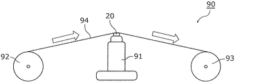
図4は、本実施の形態に係る筬羽20を摩耗させる摩耗試験装置90の構成を示す図である。図4に示すように、摩耗試験装置90は、支持台91と、巻出しローラー92と、巻取りローラー93と、タングステン線94とを備える。支持台91上には、評価対象となる筬羽20が載置されて固定される。筬羽20には、タングステン線94が所定の圧力で押し当てられている。
FIG. 4 is a diagram showing a configuration of a
タングステン線94は、巻出しローラー92と巻取りローラー93との間に架け渡されており、巻取りローラー93を回転させることで、巻出しローラー92から巻取りローラー93に向けて走行(スライド移動)する。図4には、タングステン線94の走行方向を白抜きの矢印で示している。
The
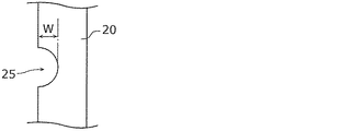
このとき、タングステン線94は、支持台91上に載置された筬羽20に接触しており、筬羽20を支持台91に押し当てるようにして走行する。タングステン線94が筬羽20に擦れ合うことで、図5に示すように、筬羽20の表面には溝25が形成される。ここで、図5は、本実施の形態に係る摩耗後の筬羽20の側面図である。ここでは、溝25の深さWを摩耗量として評価した。
At this time, the
評価対象となる筬羽20は、基材21がSK120から構成され、めっき層22がニッケルめっき層である筬羽であって、複数の粒子23がナノダイヤモンド(ND)粒子である筬羽A、及び、複数の粒子23がPTFE粒子である筬羽Bの2種類を準備した。以下では、まず、ナノダイヤモンド粒子が分散されためっき層22を有する筬羽Aの評価結果について説明する。
The
[ナノダイヤモンド粒子に関する評価結果]
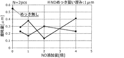
図6は、本実施の形態に係る筬羽20のナノダイヤモンド粒子の添加量と摩耗量との関係を示す図である。図6において、横軸はナノダイヤモンド粒子の添加量であり、縦軸は摩耗量、すなわち、図5で示す溝25の深さWである。なお、ナノダイヤモンド粒子の添加量は、所定の基準量(1倍)に対する倍率で表している。
[Evaluation results for nanodiamond particles]
FIG. 6 is a diagram showing the relationship between the amount of nanodiamond particles added to the
ここでは、粒子23の添加量が異なるめっき層22を表面に形成した基材21(又は、基材21の元になるリール状の金属帯)を2枚ずつ準備し、各々の摩耗量を測定した結果をプロットしている。めっき層22の厚みはいずれも1μmである。また、比較として、めっき層22を形成していない基材21に対しても摩耗試験を行い、その摩耗量も図示している。
Here, two base materials 21 (or reel-shaped metal bands from which the
図6に示すように、めっき層22を形成していない場合に比べて、摩耗量が約半分に減っていることが確認された。また、ナノダイヤモンド粒子の添加量と摩耗量とに、強い関係性は確認されなかった。
As shown in FIG. 6, it was confirmed that the amount of wear was reduced by about half compared to the case where the
以上のことから、めっき層22に粒子23としてナノダイヤモンド粒子を分散させることで、筬羽20の耐摩耗性を高めることができることが分かる。
From the above, it can be seen that the wear resistance of the
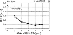
図7は、本実施の形態に係る筬羽20のめっき層22の厚みと摩耗量との関係を示す図である。図7において、横軸はめっき層22の厚みであり、縦軸は摩耗量である。めっき層22に分散させたナノダイヤモンド粒子の添加量は、所定の基準量である。
FIG. 7 is a diagram illustrating a relationship between the thickness of the
ここでは、図6の場合と同様に、粒子23の添加量が異なるめっき層22を表面に形成した基材21(又は、基材21の元になるリール状の金属帯)を2枚ずつ準備し、各々の摩耗量を測定した結果をプロットしている。また、比較として、めっき層22を形成していない基材21に対しても摩耗試験を行い、その摩耗量も図示している。
Here, as in the case of FIG. 6, two base materials 21 (or reel-shaped metal bands from which the
図7に示すように、めっき層22の厚みが大きくなる程、摩耗量が減少していることが分かる。例えば、めっき層22の厚みが1μmの場合よりも、3μm〜5μmの場合の方が、摩耗量が約3分の1に減少している。
As shown in FIG. 7, it can be seen that the amount of wear decreases as the thickness of the
なお、めっき層22の厚みが3μm以上の場合は、摩耗量は略一定である。このため、めっき層22を5μmよりも大きくしたとしても、摩耗量は略一定になると思われる。一方で、めっき層22が分厚くなった場合、めっき層22自体の剥離の発生が考えられる。したがって、めっき層22の厚みは、例えば5μm以下とすることで、めっき層22の固着性を高めつつ、筬羽20の耐摩耗性を高めることができる。
When the thickness of the
また、このとき、筬羽20の摩耗に用いたタングステン線94の表面を顕微鏡にて観察し、かつ、表面粗さRaの測定を行った。摩耗に用いる前のタングステン線94の表面粗さRaが0.14μmであったのに対して、筬羽20を摩耗させた後のタングステン線94の表面粗さRaも0.14μmであった。つまり、筬羽20の耐摩耗性が高められているにも関わらず、タングステン線94への影響がないことが分かる。
At this time, the surface of the
したがって、本実施の形態に係る筬羽20を備える筬10を用いて、タングステンからなる金属線100の製織を行ったとしても、金属線100の表面性に影響を与えない。このため、製織時の金属線100の断線などの発生を抑制することができる。
Therefore, even if weaving of the
[PTFE粒子に関する評価結果]
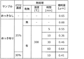
次に、PTFE粒子が分散されためっき層22を有する筬羽Bの評価結果について説明する。図8は、本実施の形態に係る筬羽20のめっき層22にPTFE粒子を分散させた場合の摩耗量の評価結果を示す図である。
[Evaluation results regarding PTFE particles]
Next, the evaluation result of the wing W having the
図8では、めっき層22内におけるPTFE粒子の濃度(具体的には、質量濃度)が25%の場合と30%の場合とを示している。また、めっき層22の形成後に熱処理を行った場合の時間と摩耗量との関係を示している。
FIG. 8 shows a case where the concentration (specifically, mass concentration) of PTFE particles in the
図8に示すように、25%の添加量でPTFE粒子が分散されためっき層22を形成した後、熱処理を行わなかった場合、めっき層22を形成していない場合よりも、摩耗量が大きくなっていることが分かる。一方で、熱処理を加えることで、摩耗量が減少している。特に、PTFE粒子の濃度によらず、熱処理時間が10分の場合には、摩耗量が低くなっている。熱処理時間が長すぎる場合(例えば60分)は、めっき層22を形成していない場合と摩耗量が略同じになっている。このため、熱処理時間は、60分より短い方がよいことが分かる。
As shown in FIG. 8, after forming the
以上のように、PTFE粒子を分散させためっき層22を形成した後、短時間の熱処理を行うことで、筬羽20の耐摩耗性を高めることができることが分かる。なお、ナノダイヤモンド粒子とPTFE粒子を混在させても構わない。
As described above, it can be seen that the wear resistance of the
[効果など]
以上のように、本実施の形態に係る筬10は、織機に利用される筬であって、間隔を空けて並んで配置された複数の筬羽20と、複数の筬羽20を支持する支持体30とを備え、複数の筬羽20の各々は、金属製の基材21と、基材21の表面に設けられためっき層22と、めっき層22内に分散された複数の粒子23とを備える。
[Effects, etc.]
As described above, the
このように、複数の粒子23が分散されためっき層22が表面に形成されているので、筬羽20の表面には、粒子23の影響によって固体潤滑性が付与される。筬羽20の表面の滑りが良くなるので、筬羽20の耐摩耗性が高められる。これにより、本実施の形態によれば、耐摩耗性に優れた筬10を提供することができる。
Thus, since the
また、例えば、複数の粒子23の各々は、ポリテトラフルオロエチレンからなる。
For example, each of the plurality of
これにより、PTFEは摩擦係数が低く、非粘着性を有する材料であるので、筬羽20の表面の滑りを良くすることができる。したがって、金属線100と筬羽20とが擦れ合ったとしても、金属線100の滑りが良くなり、摩耗量が減少する。よって、筬羽20の耐摩耗性を高めることができる。
Thereby, PTFE has a low coefficient of friction and is a non-adhesive material, so that the surface of the
また、例えば、めっき層22内の複数の粒子23の濃度は、25%以上である。
Further, for example, the concentration of the plurality of
これにより、図8で示したように、筬羽20の耐摩耗性を高めることができる。
Thereby, as shown in FIG. 8, the abrasion resistance of the
また、例えば、複数の粒子23の各々は、ナノダイヤモンド粒子、セラミックス粒子、又は、立方晶窒化ホウ素粒子であってもよい。
Further, for example, each of the plurality of
これにより、ナノダイヤモンド粒子、セラミックス粒子又はCBN粒子は、硬度が高く、かつ、摩擦係数が低いので、筬羽20の表面の滑りを良くすることができる。このため、筬羽20の耐摩耗性を高めることができる。
Thereby, since the nanodiamond particle | grains, ceramic particle | grains, or CBN particle | grains are high in hardness and a friction coefficient is low, the surface slip of the
また、例えば、めっき層22は、ニッケルを主成分として含有している。
For example, the
これにより、例えば、基材21が炭素工具鋼鋼材から形成されている場合に、基材21とめっき層22との密着性が良い。したがって、めっき層22の剥離が抑制されるので、筬羽20の信頼性を高めることができる。
Thereby, for example, when the
また、例えば、めっき層22の厚みは、1μm以上5μm以下である。
For example, the thickness of the
これにより、図7で示したように、筬羽20の耐摩耗性を高めることができる。
Thereby, as shown in FIG. 7, the abrasion resistance of the
また、例えば、基材21は、炭素工具鋼鋼材から構成されている。
For example, the
これにより、炭素工具鋼鋼材は硬度が高いので、基材21自体の変形などを抑制することができる。したがって、筬羽20が変形しにくくなるので、製織時の金属線100の断線の発生を抑制することができる。
Thereby, since carbon tool steel has high hardness, it is possible to suppress deformation of the
また、例えば、筬10は、複数の金属線100の製織を行う織機に利用される。
In addition, for example, the
これにより、高硬度の金属線100の製織では摩耗が激しくなるので、耐摩耗性に優れた筬10を利用することで、筬10を長期間使用することができる。このため、筬10のメンテナンス頻度を少なくすることができる。
As a result, the weaving of the high-
(その他)
以上、本発明に係る筬について、上記の実施の形態に基づいて説明したが、本発明は、上記の実施の形態に限定されるものではない。
(Other)
As described above, the bag according to the present invention has been described based on the above embodiment, but the present invention is not limited to the above embodiment.
例えば、上記の実施の形態では、筬10は、金属線100の製織を行う織機に利用する例を示したが、これに限らない。筬10は、化学繊維又は自然繊維を原糸として製織を行う織機に利用されてもよい。
For example, in the above-described embodiment, an example in which the
また、例えば、粒子23の例として、PTFE粒子、ナノダイヤモンド粒子、セラミックス粒子又はCBN粒子を挙げたが、これに限らない。これらと同等の摩擦係数及び硬さを有する粒子を利用してもよい。
For example, as an example of the
その他、各実施の形態に対して当業者が思いつく各種変形を施して得られる形態や、本発明の趣旨を逸脱しない範囲で各実施の形態における構成要素及び機能を任意に組み合わせることで実現される形態も本発明に含まれる。 In addition, the embodiment can be realized by arbitrarily combining the components and functions in each embodiment without departing from the scope of the present invention, or a form obtained by subjecting each embodiment to various modifications conceived by those skilled in the art. Forms are also included in the present invention.
10 筬
20 筬羽
21 基材
22 めっき層
23 粒子
30 支持体
100 金属線
10 筬 20 筬 21 21
Claims (8)
間隔を空けて並んで配置された複数の筬羽と、
前記複数の筬羽を支持する支持体とを備え、
前記複数の筬羽の各々は、
金属製の基材と、
前記基材の表面に設けられためっき層と、
前記めっき層内に分散された複数の粒子とを備える
筬。 Used for looms,
A plurality of wings arranged side by side at intervals,
A support for supporting the plurality of wings,
Each of the plurality of wings is
A metal substrate;
A plating layer provided on the surface of the substrate;
And a plurality of particles dispersed in the plating layer.
請求項1に記載の筬。 The bag according to claim 1, wherein each of the plurality of particles is made of polytetrafluoroethylene.
請求項2に記載の筬。 The wrinkle according to claim 2, wherein the concentration of the plurality of particles in the plating layer is 25% or more.
請求項1に記載の筬。 The basket according to claim 1, wherein each of the plurality of particles is nanodiamond particles, ceramic particles, or cubic boron nitride particles.
請求項1〜4のいずれか1項に記載の筬。 The bag according to any one of claims 1 to 4, wherein the plating layer contains nickel as a main component.
請求項5に記載の筬。 The wrinkle according to claim 5, wherein the plating layer has a thickness of 1 μm to 5 μm.
請求項1〜6のいずれか1項に記載の筬。 The bag according to any one of claims 1 to 6, wherein the base material is made of carbon tool steel.
請求項1〜7のいずれか1項に記載の筬。 The scissors according to claim 1, wherein the scissors are used in the loom for weaving a plurality of metal wires.
Priority Applications (1)
| Application Number | Priority Date | Filing Date | Title |
|---|---|---|---|
| JP2017093268A JP6210471B1 (en) | 2017-05-09 | 2017-05-09 | 筬 |
Applications Claiming Priority (1)
| Application Number | Priority Date | Filing Date | Title |
|---|---|---|---|
| JP2017093268A JP6210471B1 (en) | 2017-05-09 | 2017-05-09 | 筬 |
Publications (2)
| Publication Number | Publication Date |
|---|---|
| JP6210471B1 JP6210471B1 (en) | 2017-10-11 |
| JP2018188773A true JP2018188773A (en) | 2018-11-29 |
Family
ID=60040412
Family Applications (1)
| Application Number | Title | Priority Date | Filing Date |
|---|---|---|---|
| JP2017093268A Active JP6210471B1 (en) | 2017-05-09 | 2017-05-09 | 筬 |
Country Status (1)
| Country | Link |
|---|---|
| JP (1) | JP6210471B1 (en) |
Citations (9)
| Publication number | Priority date | Publication date | Assignee | Title |
|---|---|---|---|---|
| JPH0647384U (en) * | 1992-12-01 | 1994-06-28 | シチズン時計株式会社 | Reed wings for high speed loom |
| JPH07186156A (en) * | 1993-12-27 | 1995-07-25 | Mitsui Eng & Shipbuild Co Ltd | Mold for synthetic resin material and others |
| JPH0913248A (en) * | 1995-06-26 | 1997-01-14 | Nippon Oil & Fats Co Ltd | Dent for loom and its production |
| JPH1037043A (en) * | 1996-07-17 | 1998-02-10 | Citizen Watch Co Ltd | Reed dents in reed for loom and formation of coating layer on reed dents |
| JP2004225193A (en) * | 2003-01-23 | 2004-08-12 | Kanai Hiroaki | Lead material for loom and method for producing the same |
| JP2006265769A (en) * | 2005-03-24 | 2006-10-05 | Toray Ind Inc | Conductive fabric and method for producing the same |
| JP2008525658A (en) * | 2004-12-31 | 2008-07-17 | リンダウェル、ドルニエ、ゲゼルシャフト、ミット、ベシュレンクテル、ハフツング | Tangle fabric, weaving method of tangle fabric and mechanical loom |
| JP2011162807A (en) * | 2010-02-04 | 2011-08-25 | Honda Motor Co Ltd | Ni COMPOSITE PLATING |
| JP2014148719A (en) * | 2013-02-01 | 2014-08-21 | Isamu Kotani | Composite plating liquid, plating method and particle dispersion method |
-
2017
- 2017-05-09 JP JP2017093268A patent/JP6210471B1/en active Active
Patent Citations (9)
| Publication number | Priority date | Publication date | Assignee | Title |
|---|---|---|---|---|
| JPH0647384U (en) * | 1992-12-01 | 1994-06-28 | シチズン時計株式会社 | Reed wings for high speed loom |
| JPH07186156A (en) * | 1993-12-27 | 1995-07-25 | Mitsui Eng & Shipbuild Co Ltd | Mold for synthetic resin material and others |
| JPH0913248A (en) * | 1995-06-26 | 1997-01-14 | Nippon Oil & Fats Co Ltd | Dent for loom and its production |
| JPH1037043A (en) * | 1996-07-17 | 1998-02-10 | Citizen Watch Co Ltd | Reed dents in reed for loom and formation of coating layer on reed dents |
| JP2004225193A (en) * | 2003-01-23 | 2004-08-12 | Kanai Hiroaki | Lead material for loom and method for producing the same |
| JP2008525658A (en) * | 2004-12-31 | 2008-07-17 | リンダウェル、ドルニエ、ゲゼルシャフト、ミット、ベシュレンクテル、ハフツング | Tangle fabric, weaving method of tangle fabric and mechanical loom |
| JP2006265769A (en) * | 2005-03-24 | 2006-10-05 | Toray Ind Inc | Conductive fabric and method for producing the same |
| JP2011162807A (en) * | 2010-02-04 | 2011-08-25 | Honda Motor Co Ltd | Ni COMPOSITE PLATING |
| JP2014148719A (en) * | 2013-02-01 | 2014-08-21 | Isamu Kotani | Composite plating liquid, plating method and particle dispersion method |
Also Published As
| Publication number | Publication date |
|---|---|
| JP6210471B1 (en) | 2017-10-11 |
Similar Documents
| Publication | Publication Date | Title |
|---|---|---|
| JP4538049B2 (en) | Abrasive electrodeposition wire | |
| US3150470A (en) | Diamond coated wire saw | |
| CN108858839B (en) | Saw wire and cutting device | |
| CN108687981B (en) | Saw wire and cutting device | |
| JP2019131841A (en) | Metal wire and saw wire | |
| JP2016160534A (en) | Method for producing reinforcing fiber strand split yarn | |
| JP2018187739A (en) | Saw wire and cutting device | |
| WO2002007901A1 (en) | Flexible file and method for making it | |
| JPH09155631A (en) | Diamond wire saw and manufacturing method thereof | |
| JP6210471B1 (en) | 筬 | |
| US5516591A (en) | Composite plated articles having light-emitting properties | |
| JP2953673B2 (en) | Osa for high-speed loom | |
| CN108884602B (en) | Metal sulfide-coated traveler or spinning ring and method of making the same | |
| JPWO1992006234A1 (en) | High-speed loom reeds | |
| US3177113A (en) | Chromium coated papermaking wire | |
| JP6274312B2 (en) | Polishing apparatus, polishing method, and method for producing roll in molten metal plating bath | |
| Gyftou et al. | Nickel matrix composite coatings: Application in textile machinery and evaluation of cotton products quality | |
| TWI612184B (en) | Yarn guiding elements for textile machine with coating composite metal carbide ceramic electroplating layer and production method the same | |
| JP2014188655A (en) | Wire tool for polycrystalline silicon cutting and polycrystalline silicon cutting method | |
| WO2006112522A2 (en) | Surface-treated doctor blade | |
| US1355368A (en) | Metal hair | |
| JPH09105051A (en) | Dent in reed for weaving machine | |
| GB453851A (en) | Improvements in abrasive belts | |
| JPH01317963A (en) | Thread contact member | |
| JPH01149968A (en) | Manufacture of fiber sliding member |
Legal Events
| Date | Code | Title | Description |
|---|---|---|---|
| A521 | Request for written amendment filed |
Free format text: JAPANESE INTERMEDIATE CODE: A523 Effective date: 20170814 |
|
| TRDD | Decision of grant or rejection written | ||
| A01 | Written decision to grant a patent or to grant a registration (utility model) |
Free format text: JAPANESE INTERMEDIATE CODE: A01 Effective date: 20170829 |
|
| A61 | First payment of annual fees (during grant procedure) |
Free format text: JAPANESE INTERMEDIATE CODE: A61 Effective date: 20170904 |
|
| R151 | Written notification of patent or utility model registration |
Ref document number: 6210471 Country of ref document: JP Free format text: JAPANESE INTERMEDIATE CODE: R151 |