JP2018192571A - Operation auxiliary device - Google Patents
Operation auxiliary device Download PDFInfo
- Publication number
- JP2018192571A JP2018192571A JP2017098909A JP2017098909A JP2018192571A JP 2018192571 A JP2018192571 A JP 2018192571A JP 2017098909 A JP2017098909 A JP 2017098909A JP 2017098909 A JP2017098909 A JP 2017098909A JP 2018192571 A JP2018192571 A JP 2018192571A
- Authority
- JP
- Japan
- Prior art keywords
- thigh
- fastener
- arm member
- mounting member
- base material
- Prior art date
- Legal status (The legal status is an assumption and is not a legal conclusion. Google has not performed a legal analysis and makes no representation as to the accuracy of the status listed.)
- Pending
Links
- 210000000689 upper leg Anatomy 0.000 claims abstract description 106
- 239000000463 material Substances 0.000 claims abstract description 40
- 210000004394 hip joint Anatomy 0.000 claims abstract description 12
- 238000004804 winding Methods 0.000 claims abstract description 11
- 230000033001 locomotion Effects 0.000 claims description 51
- 210000001624 hip Anatomy 0.000 description 21
- 238000000034 method Methods 0.000 description 11
- 210000000629 knee joint Anatomy 0.000 description 9
- 238000006073 displacement reaction Methods 0.000 description 7
- 239000013013 elastic material Substances 0.000 description 6
- 239000004744 fabric Substances 0.000 description 5
- 230000001681 protective effect Effects 0.000 description 5
- 210000001699 lower leg Anatomy 0.000 description 4
- 230000003183 myoelectrical effect Effects 0.000 description 4
- 238000010008 shearing Methods 0.000 description 4
- 210000002414 leg Anatomy 0.000 description 3
- 229920001084 poly(chloroprene) Polymers 0.000 description 3
- 238000012545 processing Methods 0.000 description 3
- 239000002759 woven fabric Substances 0.000 description 3
- 210000003205 muscle Anatomy 0.000 description 2
- 101000911772 Homo sapiens Hsc70-interacting protein Proteins 0.000 description 1
- 229910052782 aluminium Inorganic materials 0.000 description 1
- XAGFODPZIPBFFR-UHFFFAOYSA-N aluminium Chemical compound [Al] XAGFODPZIPBFFR-UHFFFAOYSA-N 0.000 description 1
- 238000005452 bending Methods 0.000 description 1
- 230000005540 biological transmission Effects 0.000 description 1
- 239000003638 chemical reducing agent Substances 0.000 description 1
- 230000009194 climbing Effects 0.000 description 1
- 238000004891 communication Methods 0.000 description 1
- 230000008602 contraction Effects 0.000 description 1
- 238000011161 development Methods 0.000 description 1
- 230000000694 effects Effects 0.000 description 1
- 210000003414 extremity Anatomy 0.000 description 1
- 230000005484 gravity Effects 0.000 description 1
- 210000003127 knee Anatomy 0.000 description 1
- 210000003141 lower extremity Anatomy 0.000 description 1
- 229910052751 metal Inorganic materials 0.000 description 1
- 239000002184 metal Substances 0.000 description 1
- 238000012986 modification Methods 0.000 description 1
- 230000004048 modification Effects 0.000 description 1
- 239000011347 resin Substances 0.000 description 1
- 229920005989 resin Polymers 0.000 description 1
- 239000000758 substrate Substances 0.000 description 1
- 238000012546 transfer Methods 0.000 description 1
Images


Landscapes
- Manipulator (AREA)
- Rehabilitation Tools (AREA)
Abstract
Description
本発明は、人体に装着して使用され、ユーザの動作の補助力を生成する動作補助装置に関する。 The present invention relates to an operation assisting device that is used by being worn on a human body and generates an assisting force for a user's operation.
近年、人による歩行動作や階段昇降動作等の動作を補助する動作補助装置が知られている。動作補助装置は、人体装着型ロボットとも呼ばれる。動作補助装置は、人体に装着して用いられ、ユーザの動作に応じた補助力を生成することによってユーザの動作を補助する。例えば動作補助装置は、人体の関節の回転軸上に配置される関節部(能動関節部)を中心に回動可能なアーム部材を備え、アクチュエータによってアーム部材を回転駆動することによって、アーム部材が固定された人体の部分の動作を補助する。かかる動作補助装置は、例えば障害者又は高齢者だけでなく、健常者の動作を補助する装置等としても、様々な場面で使用される。 2. Description of the Related Art In recent years, an operation assisting device that assists operations such as a walking operation by a person and a stair climbing operation is known. The motion assisting device is also called a human body-mounted robot. The motion assisting device is used by being attached to a human body, and assists the user's motion by generating an assisting force corresponding to the user's motion. For example, the motion assisting device includes an arm member that can rotate around a joint portion (active joint portion) arranged on a rotation axis of a joint of a human body, and the arm member is rotated by driving the arm member by an actuator. Assist the movement of the fixed human body part. Such a motion assist device is used in various situations, for example, as a device that assists not only a disabled person or an elderly person but also a healthy person.
回動するアーム部材は、固定対象の人体の部位の外形に対応する形状のアタッチメント(装着部材)を用いて人体に固定される。例えばユーザの下肢の前後運動を補助する動作補助装置として、腰部フレームが人体の腰部に固定されるとともに、能動関節部を介して腰部フレームに対して回転自在に連結されたアーム部材が装着部材を用いて人体の大腿部又は下腿部に固定されたものがある。アーム部材を人体に固定するための装着部材の主たる目的は、アクチュエータによってアーム部材に付与された回転トルクを効率よく大腿部に伝達すること、及び、動作補助装置の重量の一部を支持することにある。ただし、ユーザの動作に伴い、能動関節部の位置と装着部材の固定位置との距離が変化するため、装着部材の固定位置がずれないようにすることは容易ではない。 The rotating arm member is fixed to the human body using an attachment (a mounting member) having a shape corresponding to the outer shape of the part of the human body to be fixed. For example, as an operation assisting device that assists the user's lower / back limb movement, the lumbar frame is fixed to the lumbar part of the human body, and the arm member that is rotatably connected to the lumbar frame via the active joint part is used as the mounting member. Some are used and fixed to the thigh or lower leg of the human body. The main purpose of the mounting member for fixing the arm member to the human body is to efficiently transmit the rotational torque applied to the arm member by the actuator to the thigh and to support a part of the weight of the motion assisting device. There is. However, since the distance between the position of the active joint portion and the fixing position of the mounting member changes with the operation of the user, it is not easy to prevent the fixing position of the mounting member from shifting.
ここで、アーム部材と装着部材との接続方式は、大別して、部材同士を強固に固定する方式と、伸縮機構等によりその接続位置に自由度を有する方式とがある。前者は、装着部材と大腿部との間にせん断力が生じ、装着部材が大腿部からずれるおそれがある。これに対して、後者は、自由度を有する方式によりせん断力が生じず、このせん断力に起因する装着部材の大腿部からのずれも生じないが、装着部材の自重に起因するずれが生じるおそれがある。 Here, the connection method between the arm member and the mounting member is roughly classified into a method in which the members are firmly fixed to each other, and a method in which the connection position is flexible by an extension mechanism or the like. In the former, a shearing force is generated between the mounting member and the thigh, and the mounting member may be displaced from the thigh. On the other hand, in the latter case, no shear force is generated by a method having a degree of freedom, and the displacement of the mounting member from the thigh due to the shear force does not occur, but the displacement due to the weight of the mounting member occurs. There is a fear.
後者の伸縮機構等による自由度を有する接続方式において、装着部材の自重を補償する例として、特許文献1には、ユーザの身体にしっかりと装着することができ、ある程度の自由度を確保することのできる歩行補助装置が開示されている。特許文献1に記載の歩行補助装置は、テレスコピック式に相対摺動可能に結合したアウタチューブとインナロッドとから構成された連結バーにより、股関節アクチュエータと膝関節アクチュエータとの間の寸法を伸縮可能にしている。また、かかる歩行補助装置において、アウタチューブ内には、例えばインナロッドに連結された引張コイルばねが組み込まれており、膝関節アクチュエータの重量が加わるインナロッドに対し、その重量を支持する向きの張力を常時作用させている。
As an example of compensating for the weight of the mounting member in the connection method having the degree of freedom by the latter expansion / contraction mechanism or the like,
上述のとおり、アーム部材と装着部材とを強固に固定する接続方式の場合、装置の自重により装着部材が大腿部からずれるおそれがある。一方、特許文献1に記載のように、接続位置に自由度を有する接続方式の場合においても、引張コイルばねのばね定数が一定の場合、股関節を回転させることでその張力の向きが重力方向と一定でなくなるために、ばねの平衡点が変化する。これにより、接続位置に自由度を有する接続方式の場合においても、依然として装着部材の自重に起因するずれが生じるおそれがある。
As described above, in the case of the connection method in which the arm member and the mounting member are firmly fixed, the mounting member may be displaced from the thigh due to the weight of the device. On the other hand, as described in
本発明は、上記問題に鑑みてなされたものであり、本発明の目的とするところは、アーム部材を大腿部に取り付けるための装着部材のずれを抑制可能な、新規かつ改良された動作補助装置を提供することにある。 The present invention has been made in view of the above problems, and an object of the present invention is to provide a new and improved motion assist capable of suppressing the displacement of the mounting member for attaching the arm member to the thigh. To provide an apparatus.
上記課題を解決するために、本発明のある観点によれば、ユーザの側方の股関節に対応する位置に配置される能動関節部と、能動関節部を中心に回動自在に支持されたアーム部材と、アーム部材の回転トルクを生成するアクチュエータと、アーム部材をユーザの大腿部に取り付けるための装着部材と、を備えた動作補助装置において、装着部材は、アーム部材が連結され大腿部に巻き付けられる基材と、基材における大腿部への巻付け方向の途中に設けられ、基材の巻付け方向の一の側の第1の部分と他の側の第2の部分とを連結する少なくとも1つのファスナーを含む締結部と、を備える、動作補助装置が提供される。 In order to solve the above-described problem, according to an aspect of the present invention, an active joint unit disposed at a position corresponding to a hip joint on a side of a user, and an arm that is rotatably supported around the active joint unit In a motion assisting device comprising a member, an actuator for generating rotational torque of the arm member, and a mounting member for attaching the arm member to the user's thigh, the mounting member is connected to the arm member and the thigh A first portion on one side and a second portion on the other side provided in the middle of the winding direction around the thigh of the substrate. And a fastening portion including at least one fastener to be connected.
以上説明したように本発明によれば、アーム部材を大腿部に取り付けるための装着部材のずれを抑制することができる。 As described above, according to the present invention, the displacement of the mounting member for attaching the arm member to the thigh can be suppressed.
以下に添付図面を参照しながら、本発明の好適な実施の形態について詳細に説明する。なお、本明細書及び図面において、実質的に同一の機能構成を有する構成要素については、同一の符号を付することにより重複説明を省略する。 Exemplary embodiments of the present invention will be described below in detail with reference to the accompanying drawings. In addition, in this specification and drawing, about the component which has the substantially same function structure, duplication description is abbreviate | omitted by attaching | subjecting the same code | symbol.
<1.動作補助装置の全体構成例>
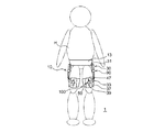
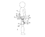
まず、図1〜図2を参照して、本実施形態に係る動作補助装置1の全体構成例について説明する。図1は、動作補助装置1の構成例を示す正面図であり、図2は、動作補助装置1の構成例を示す側面図である。
<1. Example of overall configuration of motion assist device>
First, with reference to FIGS. 1-2, the example of whole structure of the
本実施形態に係る動作補助装置1は、アーム部材33と大腿部装着部材100とがスライド機構50を介して接続され、接続位置に自由度を有する接続方式により構成された例である。動作補助装置1は、人体の股関節の左右の側方に配置された第1の関節部(能動関節部)30を有し、左右の下肢の前後運動の補助力を付与することで歩行動作又は階段昇降動作等を補助する装置として構成されている。動作補助装置1は、いわゆる外骨格ロボットとも呼ばれる。動作補助装置1は、装着具10と、アクチュエータ20と、制御装置22とを備える。本実施形態に係る動作補助装置1において、装着具10は、腰部フレーム31と、腰部固定ベルト13と、アーム部材33と、大腿部装着部材100と、スライド機構50とを備える。本実施形態において、大腿部装着部材100は、本発明における装着部材に相当する部材である。
The
装着具10のうち、腰部フレーム31及びアーム部材33は、例えばアルミニウム等の軽金属又は樹脂材料により形成され、所定程度の剛性を有する。したがって、腰部フレーム31及びアーム部材33は、変形しにくい構成要素である。一方、腰部固定ベルト13は、大腿部への締め付け力を生じさせることができるように、伸縮性の織物、編物又は弾性材料等により形成されている。弾性材料としては、例えば機械的強度及び耐候性に優れ、さらに耐熱性、耐寒性及び耐油性を併せ持つクロロプレンゴムが好適に用いられる。
Of the
腰部フレーム31は、ユーザHの人体の腰部に配置され、腰部固定ベルト13により固定される。腰部固定ベルト13は、例えばバックル又は面ファスナー等の図示しない連結具を有し、連結具を連結することにより腰部固定ベルト13が巻き付けられて腰部フレーム31が腰部に固定される。腰部フレーム31の下方側は、腰部の側方に位置する部位へと延びている。
The
腰部フレーム31のうち、人体の側部に位置する部分には第1の関節部30及び第2の関節部90を介してアーム部材33が接続されている。このうち第1の関節部30は、アクチュエータ20により回転駆動される能動関節である。第1の関節部30は、ユーザHの人体の股関節の側方に位置し、股関節の回転軸上に配置される。第1の関節部30は、人体の股関節の曲げ伸ばし動作に対応して腰部フレーム31と、第2の関節部90を含むアーム部材33とを相対回転可能に連結する。つまり、第1の関節部30は、腰部フレーム31及びアーム部材33を人体の前後方向に沿って相対的に回動可能にする。
An
第2の関節部90は、ユーザHの動作に合わせて回転する受動関節部である。第2の関節部90は、人体の股関節の内転動作及び外転動作に対応して腰部フレーム31及びアーム部材33を相対回転可能に連結する。つまり、第2の関節部90は、腰部フレーム31及びアーム部材33を人体の側方へと相対的に回動可能にする。なお、第2の関節部90は省略されていてもよいが、動作補助装置1が第1の関節部30と併せて第2の関節部90を有することにより、人体の股関節の動きに対応して動作する動作補助装置1の自由度が高められる。
The second
アーム部材33は、第1の関節部30からユーザHの大腿部に沿って下方に延びる。アーム部材33の下方側には、スライド機構50を介して大腿部装着部材100が接続されている。スライド機構50は、アーム部材33と大腿部装着部材100とを人体の大腿部の長さ方向へ相対的にスライド自在に連結する。スライド機構50の構成は特に限定されるものではなく、例えばガイドレール39と、複数の図示しない転送ボールを介してガイドレール39上に組み付けられた可動ブロック47とを含む装置であってもよい。かかるスライド機構50の例では、ガイドレール39がユーザの大腿部の長さ方向に沿って配置され、可動ブロック47がアーム部材33の下方側に取り付けられる。
The
これにより、ユーザHの動作に伴って第1の関節部30と、大腿部装着部材100の大腿部への固定位置との間の距離が変化した場合に、アーム部材33と大腿部装着部材100とが相対移動して、せん断力を低減することができる。特に、本実施形態に係る動作補助装置1は、腰部フレーム31とアーム部材33とが第1の関節部30だけでなく第2の関節部90を介して連結されており、第1の関節部30と、大腿部装着部材100の固定位置との間の距離が変化しやすくなっているものの、スライド機構50を備えているためにせん断力を低減することができる。
As a result, when the distance between the first
大腿部装着部材100は、基材37を有する。基材37は、基材37は、スライド機構50を介してアーム部材33に連結され、ユーザHの大腿部に巻き付けられる。基材37には、スライド機構50のガイドレール39が取り付けられている。大腿部装着部材100は、図示しない連結具を備え、基材37を大腿部に巻き付けた状態で連結具を連結することにより基材37が大腿部に固定される。基材37は、少なくとも一部が伸縮性の織物、編物又は弾性材料等により形成されている。弾性材料としては、例えば機械的強度及び耐候性に優れ、さらに耐熱性、耐寒性及び耐油性を併せ持つクロロプレンゴムが好適に用いられる。なお、本実施形態に係る動作補助装置1の大腿部装着部材100の具体的な構成は、後で詳しく説明する。
The
動作補助装置1は、筋電位信号等のユーザの生体信号を検出する図示しない生体信号センサを備える。生体信号センサは、人体の大腿部の皮膚に直接装着される接触式のセンサであってもよく、あるいは、衣服等を介して大腿部の表面に設置される非接触式のセンサであってもよい。生体信号センサは、動作補助装置1が補助する筋力に対応する運動単位(筋肉)の位置に合わせて設置される。本実施形態に係る動作補助装置1は、ユーザHの左右の下肢の前後運動を補助する装置であり、生体信号センサの表面電極(検出電極)は、例えばユーザHの左右の大腿四頭筋の筋電位を検出可能な位置に配置される。
The
腰部フレーム31の背中側にはケース5が備えられる。ケース5内には制御装置22及びバッテリユニット25が収容されている。制御装置22は、生体信号センサにより検出される筋電位信号等の生体信号の情報を取得して演算処理を行い、アクチュエータ20に供給する電流を制御する。制御装置22は、例えばCPU(Central Processing Unit)又はMPU(Micro Processing Unit)等のプロセッサ及び記憶素子等の電子部品を備えて構成され、生体信号センサ及びアクチュエータ20に対して電気的に接続される。制御装置22と、生体信号センサ又はアクチュエータ20とは、無線の通信手段によって接続されてもよい。
A
本実施形態に係る動作補助装置1において、アクチュエータ20は、第1の関節部30に設けられている。アクチュエータ20としては、例えばステッピングモータ又はブラシレスモータからなるロータリモータが用いられる。アクチュエータ20は、アクチュエータ20が出力する回転を減速する減速機を有していてもよい。アクチュエータ20が出力する回転トルクにより、第1の関節部30を介して腰部フレーム31に連結されたアーム部材33が第1の関節部30を中心に回動する。これにより、アーム部材33が固定されたユーザHの大腿部の前後方向の動きが補助される。
In the
なお、アクチュエータ20は、第1の関節部30から離れた位置に設けられていてもよい。この場合、アクチュエータ20が出力する回転トルクは、例えばプーリ及び可撓性ケーブル等を含む動力伝達機構を介して第1の関節部30に伝達され、第1の関節部30の回動駆動が制御される。アクチュエータ20が第1の関節部30から離れた位置に設けられる場合、アクチュエータ20は、回転式のロータリモータに限られず、リニアモータと回転機構とを組み合わせたアクチュエータであってもよい。
The
かかる動作補助装置1では、ユーザHの動作意思に伴って生成される筋電位信号等の生体信号の情報が生体信号センサにより検出され、制御装置22が当該生体信号の情報に基づき第1の関節部30あるいはアクチュエータ20の要求トルクを算出する。また、制御装置22は、算出した要求トルクに基づいてアクチュエータ20の制御量(例えば供給電流)を決定し、アクチュエータ20の駆動を制御する。これにより、アクチュエータ20が回転駆動し、アーム部材33が回転することによって、ユーザHの下肢の前後動作に対する補助力が生成される。
In the
<2.大腿部装着部材の構成例>
次に、図3を参照して、本実施形態に係る動作補助装置1に設けられた大腿部装着部材100の構成例について説明する。図3は、大腿部装着部材100の構成例を示す説明図であって、大腿部装着部材100を展開した状態を示す展開図である。
<2. Configuration example of thigh attachment member>
Next, a configuration example of the
大腿部装着部材100は、基材37と、連結具121,123と、締結部110とを含む。基材37は、大腿部への巻付け方向の一の側の第1の部分37aと他の側の第2の部分37bとを有し、第1の部分37aと第2の部分37bとは締結部110を介して連結されている。締結部110は、基材37の第1の部分37aと第2の部分37bとを、大腿部への巻付け方向に連結している。上述のとおり、基材37の第1の部分37a又は第2の部分37bの少なくとも一方は、伸縮性の織物又は編物、あるいは弾性材料により構成されている。
The
第1の部分37aは、装着時において大腿部の前面側に位置する部分であり、第1の部分37aにはスライド機構50のガイドレール39が取り付けられている。ガイドレール39は、大腿部の長さ方向に沿って、つまり、大腿部への巻付け方向に対して交差する方向に沿って配置されている。このガイドレール39には図示しない可動ブロックがガイドレール39の長さ方向へと移動自在に取り付けられており、アーム部材33は可動ブロックを介してガイドレール39に接続されている。これにより、アーム部材33と大腿部装着部材100とが相対的にスライド可能になっている。なお、図3において、図の上側が股関節側であり下側が膝関節側であり、アーム部材33は上方に向かって伸びている。
The first portion 37a is a portion located on the front side of the thigh when worn, and the
本実施形態において、第2の部分37bは、例えば装着時において大腿部の背面側に位置する部分であり、締結部110とは反対の端部側に連結具121,123としての面ファスナーを有する。基材37を大腿部に巻き付けた状態で、第2の部分37bに設けられた連結具121,123としての面ファスナーを第1の部分37aに貼り付けることによって、大腿部装着部材100が大腿部に固定される。連結具121,123は面ファスナーでなくてもよく、例えばバックルを用いて連結されるものでもよい。
In the present embodiment, the second portion 37b is a portion that is positioned on the back side of the thigh at the time of wearing, for example, and hook fasteners as the connecting
締結部110は、基材37の大腿部への巻付け方向の途中に設けられ、第1の部分37aと第2の部分37bとを連結する少なくとも1つのファスナー111,113を含む。本実施形態では、締結部110は、第1のファスナー111と第2のファスナー113とを含む。第1のファスナー111のスライダ111a及び第2のファスナー113のスライダ113aは、いずれも基材37の大腿部への巻付け方向に交差する方向に移動する。したがって、第1のファスナー111又は第2のファスナー113の少なくとも一方の締結又は開放によって、基材37の全体長さが伸縮する。
The
第1のファスナー111のスライダ111aの移動方向と、第2のファスナー113のスライダ113aの移動方向とは、逆となっている。第1のファスナー111は、スライダ111aを下方に移動させることにより締結され、スライダ111aを上方に移動させることにより開放される。第1のファスナー111は、開放時において下方に向かって扇状に開かれているため、第1のファスナー111を締結することにより、主として大腿部の膝関節側の基材37の締め付け力を増大させることができる。一方、第2のファスナー113は、スライダ113aを上方に移動させることにより締結され、スライダ113aを下方に移動させることにより開放される。第2のファスナー113は、開放時において上方に向かって扇状に開かれているため、第2のファスナー113を締結することにより、主として大腿部の根元側の基材37の締め付け力を増大させることができる。
The moving direction of the
このように第1のファスナー111又は第2のファスナー113のうちの少なくとも一方を締結し、大腿部への基材37の締め付け力を増大させることにより、大腿部装着部材100の位置ずれを抑制することができる。このとき、締結部110は、少なくとも一つのファスナーを有していればよい。その際に、スライダを上下いずれの方向に移動させてファスナーを締結するようにするかは、大腿部の膝関節側又は根元側のいずれに対する締め付け力を増大させたいかに基づいて選択することができる。ただし、本実施形態に係る大腿部装着部材100のように、締結時のスライダ111a,113aの移動方向が逆である第1のファスナー111及び第2のファスナー113を備えることにより、ユーザあるいは補助者が任意のファスナーを選択して基材37を締め付けることができる。あるいは、第1のファスナー111及び第2のファスナー113をともに締め付けることによって、基材37を均一に締め付けることができる。
In this way, by fastening at least one of the
なお、本実施形態において、大腿部装着部材100の基材37は、第1のファスナー111及び第2のファスナー113の位置においても、第3の部分37c及び第4の部分37dにより繋がっており、完全に分離していない。このため、第1のファスナー111及び第2のファスナー113を開放した状態においても取扱いが容易になっている。ただし、第1のファスナー111及び第2のファスナー113によって連結される基材37の第1の部分37aと第2の部分37bとは、大腿部への巻付け方向へと完全に分離していてもよい。
In the present embodiment, the
また、大腿部装着部材100は、締結部110から基材37の第2の部分37b側に延びる二つの保護ベルト131,135を備えている。保護ベルト131,135はそれぞれ先端側に面ファスナー133,137を有する。保護ベルト131,135は締結部110を覆うように第1の部分37a側に折り返されて、面ファスナー133,137が第1の部分37aに貼り付けられる。これにより、第1のファスナー111又は第2のファスナー113の少なくとも一方により基材37を締め付けた状態を補強し、締結された第1のファスナー111又は第2のファスナー113が自然に開放されることが抑制される。保護ベルト131,135の数は二つに限られない。
Further, the
なお、締結部110は、三つ以上のファスナーを有していてもよい。また、本実施形態の例では、一つの締結部110に第1のファスナー111及び第2のファスナー113が設けられているが、二つ以上のファスナーを用いる場合、締結部が二つ以上に分離されていてもよい。例えば、大腿部の内側に、スライダ111aを下方に移動させて締め付ける構成の第1のファスナー111を有する締結部が設けられ、大腿部の外側に、スライダ113aを上方に移動させて締め付ける構成の第2のファスナー113を有する締結部が設けられてもよい。
The
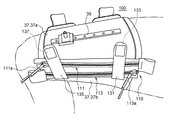
次に、図3〜図5を参照して、本実施形態に係る動作補助装置1の大腿部装着部材100を人体の大腿部に装着する様子を説明する。図3〜図5は、人体の右脚の大腿部に大腿部装着部材100を取り付ける様子を示している。なお、図3及び図4は、直立状態の人体の右脚の大腿部を正面から見た様子を示し、図5は、右膝を上げた状態の人体の右脚の大腿部を内側から見た様子を示している。図5中、アーム部材33の図示は省略されている。
Next, with reference to FIGS. 3 to 5, how the
まず、図3に示すように、第1のファスナー111及び第2のファスナー113がいずれも開放された状態で、スライド機構50のガイドレール39が大腿部の前面に位置するように大腿部装着部材100が配置される。
First, as shown in FIG. 3, with both the
次いで、図4に示すように、基材37が大腿部に巻き付けられ、基材37の第2の部分37bの端部に設けられている連結具121,123としての面ファスナーが基材37の第1の部分37aに貼り付けられる。例えば、基材37の伸縮性あるいは弾性を活かして、大腿部粗着部材100が大腿部を軽く締め付ける程度に基材37が大腿部に巻き付けられる。その後、第1のファスナー111のスライダ111aが移動され、第1のファスナー111が締結される。これにより、大腿部の膝関節側の基材37の締め付け力が増大される。
Next, as shown in FIG. 4, the
次いで、図5に示すように、第2のファスナー113のスライダ113aが移動され、第2のファスナー113が締結される。これにより、大腿部の根元側の基材37の締め付け力が増大される。さらに、基材37の第2の部分37b側に延びる二つの保護ベルト131,135が締結部110を覆うように折り返されて、保護ベルト131,135の先端側に設けられた面ファスナー133,137が第1の部分37aに貼り付けられる。
Next, as shown in FIG. 5, the
なお、第1のファスナー111及び第2のファスナー113がいずれも締結されることは必須ではなく、ユーザ又は補助者等は、締め付け力を増大させたい位置に応じて、第1のファスナー111又は第2のファスナー113の少なくとも一方を締結すればよい。さらに、第1のファスナー111又は第2のファスナー113を締結する際には完全に締結されなくてもよく、途中まで締結されてもよい。これにより、締め付け力を増大させる程度あるいは範囲を調節することができる。
Note that it is not essential that both the
<4.本実施形態による効果>
以上説明したように、本実施形態に係る動作補助装置1によれば、能動関節部である第1の関節部30に対して回動自在に連結されたアーム部材33を大腿部に固定するための大腿部装着部材100が、基材37における大腿部への巻付け方向の途中に設けられ、基材37の第1の部分37aと第2の部分37bとを連結する少なくとも1つのファスナーを含む締結部110を備えている。したがって、基材37を大腿部に巻き付けた後にファスナーを締結することにより、大腿部への基材37の締め付け力を増大させることができる。これにより、ユーザの動作時における大腿部装着部材100の位置ずれを抑制することができる。
<4. Effects according to this embodiment>
As described above, according to the
また、本実施形態に係る動作補助装置1において、基材37の少なくとも一部が伸縮性を有する織物又は編物、あるいは弾性材料により構成される場合には、締結部110のファスナーを締結する前において、基材37の締め付け力を発生させた上で、さらにファスナーを締結させて締め付け力を増大させることができる。したがって、ファスナーの締め付け前に仮決めした大腿部装着部材100の位置がずれにくくなって、ファスナーの締め付け前後における大腿部装着部材100の位置ずれを抑制することができる。特に、基材37の少なくとも一部がクロロプレンゴムから形成されていることにより、基材37に耐熱性、耐寒性及び耐油性を持たせつつ、機械的強度及び耐候性を向上させることができる。
Further, in the
また、本実施形態に係る動作補助装置1において、締結部110が、ファスナーを締結する際のスライダの移動方向が逆である第1のファスナー111及び第2のファスナー113を備えている場合には、ユーザあるいは補助者等により、膝関節側又は大腿部の根元側のいずれにおいて基材の締め付け力を増大させるかを選択することができる。あるいは、膝関節側及び大腿部の根元側の両方において、基材の締め付け力を増大させることができる。したがって、大腿部装着部材100の装着時における自由度を高めることができる。
Moreover, in the
また、本実施形態に係る動作補助装置1において、アーム部材33と大腿部装着部材100とがスライド機構50を介して連結されている場合には、ユーザの動作に伴って、第1の関節部30と、大腿部装着部材100の固定位置との間の距離が変わったとしても大腿部装着部材100に作用するせん断力が低減され、大腿部装着部材100の位置ずれをより抑制することができる。
Moreover, in the
以上、添付図面を参照しながら本発明の好適な実施形態について詳細に説明したが、本発明はかかる例に限定されない。本発明の属する技術の分野における通常の知識を有する者であれば、特許請求の範囲に記載された技術的思想の範疇内において、各種の変更例または修正例に想到し得ることは明らかであり、これらについても、当然に本発明の技術的範囲に属するものと了解される。 The preferred embodiments of the present invention have been described in detail above with reference to the accompanying drawings, but the present invention is not limited to such examples. It is obvious that a person having ordinary knowledge in the technical field to which the present invention pertains can come up with various changes or modifications within the scope of the technical idea described in the claims. Of course, it is understood that these also belong to the technical scope of the present invention.
例えば、上記実施形態では、動作補助装置が、アーム部材と大腿部装着部材とを接続するスライド機構を備え、接続位置に自由度を有する接続方式により構成されていたが、本発明はかかる例に限定されない。動作補助装置は、当該リニアガイド装置を備えずにアーム部材と装着部材とを強固に固定する接続方式により構成されていてもよい。かかる動作補助装置に本発明を適用した場合であっても、大腿部装着部材の締め付け力が増大され、大腿部装着部材の位置ずれを抑制することができる。 For example, in the above-described embodiment, the motion assisting device includes the slide mechanism that connects the arm member and the thigh mounting member, and is configured by a connection method having a degree of freedom in the connection position. It is not limited to. The motion assisting device may be configured by a connection method that firmly fixes the arm member and the mounting member without including the linear guide device. Even when the present invention is applied to such a motion assisting device, the tightening force of the thigh mounting member is increased, and the displacement of the thigh mounting member can be suppressed.
また、上記実施形態では、動作補助装置が、ユーザの両脚の前後運動を補助する装置として構成されていたが、本発明はかかる例に限定されない。例えば動作補助装置は、ユーザの片脚の前後運動を補助する装置であってもよい。この場合、第1の腰部関節部、第2の腰部関節部、膝部関節部、腰部フレーム、大腿部アーム部材、下腿部アーム部材、基材及び下腿部装着部は、左右のいずれか一方にのみ設けられる。 Moreover, in the said embodiment, although the operation assistance apparatus was comprised as an apparatus which assists the user's both legs back-and-forth movement, this invention is not limited to this example. For example, the motion assisting device may be a device that assists the user's one leg back and forth movement. In this case, the first lumbar joint, the second lumbar joint, the knee joint, the lumbar frame, the thigh arm member, the crus arm member, the base material, and the crus attachment part may be left or right. It is provided only on one side.
1・・・動作補助装置、20・・・アクチュエータ、22・・・制御装置、30・・・第1の関節部(能動関節部)、31・・・腰部フレーム、33・・・アーム部材、37・・・基材、37a・・・第1の部分、37b・・・第2の部分、50・・・スライド機構、100・・・大腿部装着部材、110・・・締結部、111・・・第1のファスナー、111a・・・スライダ、113・・・第2のファスナー、113a・・・スライダ
DESCRIPTION OF
Claims (4)
前記装着部材は、
前記アーム部材が連結され前記大腿部に巻き付けられる基材と、
前記基材における前記大腿部への巻付け方向の途中に設けられ、前記基材の前記巻付け方向の一の側の第1の部分と他の側の第2の部分とを連結する少なくとも1つのファスナーを含む締結部と、
を備える、動作補助装置。 An active joint portion disposed at a position corresponding to a hip joint on a side of the user, an arm member supported rotatably about the active joint portion, an actuator for generating a rotational torque of the arm member, A mounting member for attaching an arm member to the thigh of the user,
The mounting member is
A base material to which the arm member is connected and wound around the thigh;
Provided in the middle of the winding direction around the thigh in the base material, and connecting at least a first portion on one side of the base material with a second portion on the other side of the base material. A fastening portion including one fastener;
A motion assisting device.
第1のファスナーを締結する際のスライダの移動方向と、第2のファスナーを締結する際のスライダの移動方向と、が逆である、請求項1又は2に記載の動作補助装置。 The fastening portion includes at least two fasteners,
The motion assisting device according to claim 1 or 2, wherein a moving direction of the slider when fastening the first fastener is opposite to a moving direction of the slider when fastening the second fastener.
The motion assist device according to claim 1, further comprising a slide mechanism that slidably connects the arm member and the mounting member along a length direction of the thigh.
Priority Applications (1)
| Application Number | Priority Date | Filing Date | Title |
|---|---|---|---|
| JP2017098909A JP2018192571A (en) | 2017-05-18 | 2017-05-18 | Operation auxiliary device |
Applications Claiming Priority (1)
| Application Number | Priority Date | Filing Date | Title |
|---|---|---|---|
| JP2017098909A JP2018192571A (en) | 2017-05-18 | 2017-05-18 | Operation auxiliary device |
Publications (1)
| Publication Number | Publication Date |
|---|---|
| JP2018192571A true JP2018192571A (en) | 2018-12-06 |
Family
ID=64571011
Family Applications (1)
| Application Number | Title | Priority Date | Filing Date |
|---|---|---|---|
| JP2017098909A Pending JP2018192571A (en) | 2017-05-18 | 2017-05-18 | Operation auxiliary device |
Country Status (1)
| Country | Link |
|---|---|
| JP (1) | JP2018192571A (en) |
Cited By (1)
| Publication number | Priority date | Publication date | Assignee | Title |
|---|---|---|---|---|
| JP2023011926A (en) * | 2017-08-23 | 2023-01-24 | サムスン エレクトロニクス カンパニー リミテッド | exercise aid |
-
2017
- 2017-05-18 JP JP2017098909A patent/JP2018192571A/en active Pending
Cited By (4)
| Publication number | Priority date | Publication date | Assignee | Title |
|---|---|---|---|---|
| JP2023011926A (en) * | 2017-08-23 | 2023-01-24 | サムスン エレクトロニクス カンパニー リミテッド | exercise aid |
| JP7549845B2 (en) | 2017-08-23 | 2024-09-12 | サムスン エレクトロニクス カンパニー リミテッド | Exercise Support Devices |
| JP2024180385A (en) * | 2017-08-23 | 2024-12-26 | サムスン エレクトロニクス カンパニー リミテッド | Exercise Support Devices |
| JP7765574B2 (en) | 2017-08-23 | 2025-11-06 | サムスン エレクトロニクス カンパニー リミテッド | exercise aid device |
Similar Documents
| Publication | Publication Date | Title |
|---|---|---|
| EP3954351B1 (en) | Ankle-assisted exoskeleton device | |
| CN104940004B (en) | Joint assembly and walking auxiliary robot | |
| CN110314065B (en) | Exoskeleton rehabilitation assist device | |
| US10799381B2 (en) | Tendon device for suit type robot for assisting human with physical strength | |
| KR101142240B1 (en) | Wearable robot to assist muscular strength | |
| US10702400B2 (en) | Mechanical exoskeleton wearable apparatus, operation control method and operation control device for the same | |
| US20180338880A1 (en) | Assist device | |
| JP2020518295A5 (en) | ||
| US20220401285A1 (en) | Device for assisting motion of a joint | |
| KR102443794B1 (en) | exercise aids | |
| CN112025681B (en) | Electric waist assisting exoskeleton | |
| WO2017026943A1 (en) | Exosuit | |
| JP2009213538A (en) | Assisting brace and its control method | |
| JP2007282991A (en) | Lumbar region support device | |
| JP2018094635A (en) | Motion assisting device | |
| KR102207991B1 (en) | Flexible Sheet Type Muscular Strength Assisting Suit | |
| KR101822946B1 (en) | Wearable robot with flexible strap | |
| JP2018192571A (en) | Operation auxiliary device | |
| KR102530849B1 (en) | Module-based upper-limb rehabilitation robot that is able to be disassembled or combined | |
| JP7819704B2 (en) | Assist device and assist belt | |
| KR101653100B1 (en) | A leg action assist apparatus with Reverse drive is easy | |
| JP2005000339A (en) | Strength assist device | |
| KR101947267B1 (en) | Knee supporting device for walking assist | |
| JP2019205634A (en) | Motion support device and fixtures of motion support device | |
| JP7648059B2 (en) | Support unit having a bistable spring and exercise support device including the same |