JP2019012006A - Optical measuring device - Google Patents
Optical measuring device Download PDFInfo
- Publication number
- JP2019012006A JP2019012006A JP2017128275A JP2017128275A JP2019012006A JP 2019012006 A JP2019012006 A JP 2019012006A JP 2017128275 A JP2017128275 A JP 2017128275A JP 2017128275 A JP2017128275 A JP 2017128275A JP 2019012006 A JP2019012006 A JP 2019012006A
- Authority
- JP
- Japan
- Prior art keywords
- light
- light receiving
- measurement
- image
- receiving surface
- Prior art date
- Legal status (The legal status is an assumption and is not a legal conclusion. Google has not performed a legal analysis and makes no representation as to the accuracy of the status listed.)
- Granted
Links
Images





Classifications
-
- G—PHYSICS
- G01—MEASURING; TESTING
- G01B—MEASURING LENGTH, THICKNESS OR SIMILAR LINEAR DIMENSIONS; MEASURING ANGLES; MEASURING AREAS; MEASURING IRREGULARITIES OF SURFACES OR CONTOURS
- G01B11/00—Measuring arrangements characterised by the use of optical techniques
-
- G—PHYSICS
- G01—MEASURING; TESTING
- G01B—MEASURING LENGTH, THICKNESS OR SIMILAR LINEAR DIMENSIONS; MEASURING ANGLES; MEASURING AREAS; MEASURING IRREGULARITIES OF SURFACES OR CONTOURS
- G01B11/00—Measuring arrangements characterised by the use of optical techniques
- G01B11/002—Measuring arrangements characterised by the use of optical techniques for measuring two or more coordinates
-
- G—PHYSICS
- G01—MEASURING; TESTING
- G01B—MEASURING LENGTH, THICKNESS OR SIMILAR LINEAR DIMENSIONS; MEASURING ANGLES; MEASURING AREAS; MEASURING IRREGULARITIES OF SURFACES OR CONTOURS
- G01B11/00—Measuring arrangements characterised by the use of optical techniques
- G01B11/02—Measuring arrangements characterised by the use of optical techniques for measuring length, width or thickness
-
- G—PHYSICS
- G01—MEASURING; TESTING
- G01B—MEASURING LENGTH, THICKNESS OR SIMILAR LINEAR DIMENSIONS; MEASURING ANGLES; MEASURING AREAS; MEASURING IRREGULARITIES OF SURFACES OR CONTOURS
- G01B11/00—Measuring arrangements characterised by the use of optical techniques
- G01B11/02—Measuring arrangements characterised by the use of optical techniques for measuring length, width or thickness
- G01B11/028—Measuring arrangements characterised by the use of optical techniques for measuring length, width or thickness by measuring lateral position of a boundary of the object
-
- G—PHYSICS
- G01—MEASURING; TESTING
- G01B—MEASURING LENGTH, THICKNESS OR SIMILAR LINEAR DIMENSIONS; MEASURING ANGLES; MEASURING AREAS; MEASURING IRREGULARITIES OF SURFACES OR CONTOURS
- G01B11/00—Measuring arrangements characterised by the use of optical techniques
- G01B11/26—Measuring arrangements characterised by the use of optical techniques for measuring angles or tapers; for testing the alignment of axes
Landscapes
- Physics & Mathematics (AREA)
- General Physics & Mathematics (AREA)
- Length Measuring Devices By Optical Means (AREA)
Abstract
【課題】光学測定装置において測定精度の向上を簡易に実現すること。【解決手段】投光部10は、測定対象物500が配置される測定空間101へ、X方向に平行に光を投射する。受光部30は、受光面31に投射される光の二次元分布を示す信号SIGを出力する。光学系20は、測定空間101を通過する光を受光部30の受光面31へ導く。制御部40は、受光部30から出力される信号SIGに基づいてX方向における測定対象物500の位置を検出する。受光面31は、投射される光の投射方向に対して、Z方向を軸として角度θだけ傾いている。制御部40は、信号SIGに基づいて光の二次元分布においてZ方向で光量が所定量変化している箇所を検出し、検出した箇所のY方向での位置を検出し、検出した位置に基づいて測定対象物500が配置された測定空間101内のX方向における位置を検出する。【選択図】図1An object of the present invention is to easily improve measurement accuracy in an optical measuring apparatus. A light projecting unit projects light in parallel to an X direction onto a measurement space in which a measurement object is placed. The light receiving unit 30 outputs a signal SIG indicating a two-dimensional distribution of light projected on the light receiving surface 31. The optical system 20 guides light passing through the measurement space 101 to the light receiving surface 31 of the light receiving unit 30. The control unit 40 detects the position of the measurement object 500 in the X direction based on the signal SIG output from the light receiving unit 30. The light receiving surface 31 is inclined by an angle θ with respect to the projection direction of the projected light with the Z direction as an axis. Based on the signal SIG, the control unit 40 detects a location where the light amount changes in the Z direction by a predetermined amount in the two-dimensional light distribution, detects the position of the detected location in the Y direction, and based on the detected location. The position in the X direction in the measurement space 101 where the measurement object 500 is arranged is detected. [Selection] Figure 1
Description
本発明は、光学測定装置に関する。 The present invention relates to an optical measuring device.
測定対象物に光を投射して、イメージセンサでその透過光又は反射光を受けて受光量分布を測定することで、測定対象物の寸法、位置、形状等を測定する光学測定装置が知られている。 An optical measurement device that measures the size, position, shape, etc. of a measurement object by projecting light onto the measurement object and measuring the received light amount distribution by receiving the transmitted or reflected light with an image sensor is known. ing.
このような光学測定装置として、測定空間内に置かれた測定対象物の位置を検出することができる光学測定装置が提案されている(特許文献1)。この光学測定装置では、投光部から、測定対象物が置かれる測定空間へ光が投射される。測定空間を通過した光は、第1の光学系を通して第1のイメージセンサに導かれ、かつ、第2の光学系を通して第2のイメージセンサに導かれる。光軸に直交する方向における測定対象物のエッジの位置は、第1のイメージセンサの出力信号に基づいて算出される。この光学測定装置では、測定空間内における、光軸方向における第1の光学系の第1の焦点の位置と第2の光学系の第2の焦点の位置とが互いに異なるように構成される。これにより、第1のイメージセンサ及び第2のイメージセンサの出力信号に基づいて、測定対象物が、第1の焦点を基準として光軸方向のどの位置にあるかを判定することができる。 As such an optical measurement apparatus, an optical measurement apparatus capable of detecting the position of a measurement object placed in a measurement space has been proposed (Patent Document 1). In this optical measurement apparatus, light is projected from the light projecting unit to the measurement space where the measurement object is placed. The light that has passed through the measurement space is guided to the first image sensor through the first optical system, and is guided to the second image sensor through the second optical system. The position of the edge of the measurement object in the direction orthogonal to the optical axis is calculated based on the output signal of the first image sensor. This optical measurement apparatus is configured such that the position of the first focus of the first optical system and the position of the second focus of the second optical system in the optical axis direction in the measurement space are different from each other. Thereby, based on the output signals of the first image sensor and the second image sensor, it can be determined which position in the optical axis direction the measurement object is based on the first focus.
ところが、上述の光学測定装置には、以下に示す問題点が有る。上述の光学測定装置は、2つの光学系のそれぞれを介して、2つのイメージセンサによって光を受光して、それぞれの焦点位置を利用して測定対象物の位置を検出している。そのため、測定用の二次元イメージセンサとは別に、位置検出のための一次元イメージセンサが2つ必要となる。また、位置検出のためのイメージセンサに光を導くために、ビームスプリッタやハーフミーなど、光を分岐、配向させる光学部品も必要となる。その結果、光学部品の数が多くなり、光学測定装置が大型化してしまう。そのため、光学測定装置の高コスト化を招き、かつ、各光学部品の調整に多大な労力が必要となってしまう。 However, the above-described optical measuring device has the following problems. The optical measurement apparatus described above receives light by two image sensors through each of the two optical systems, and detects the position of the measurement object using the respective focal positions. For this reason, two one-dimensional image sensors for position detection are required separately from the two-dimensional image sensor for measurement. In addition, in order to guide the light to the image sensor for position detection, an optical component such as a beam splitter or a half-medium for branching and orienting the light is required. As a result, the number of optical components increases, and the optical measuring device increases in size. For this reason, the cost of the optical measuring device is increased, and much effort is required for adjusting each optical component.
本発明は、上記の事情に鑑みて成されたものであり、本発明の目的は、光学測定装置において測定精度の向上を簡易に実現することである。 The present invention has been made in view of the above circumstances, and an object of the present invention is to easily realize improvement in measurement accuracy in an optical measurement apparatus.
本発明の第1の態様である光学測定装置は、
測定対象物が配置される測定空間へ、第1の方向に平行に光を投射する投光部と、
受光面に投射される光の二次元分布を示す信号を出力する受光部と、
前記測定空間を通過する光を前記受光部の前記受光面へ導く光学系と、
前記受光部から出力される前記信号に基づいて前記第1の方向における前記測定対象物の位置を検出する制御部と、を有し、
前記受光部の前記受光面は、前記受光面に投射される光の投射方向に対して、前記第1の方向と直交する第2の方向を軸として所定角度だけ傾いており、
前記制御部は、前記受光部から出力される前記信号に基づいて、前記光の二次元分布において前記第2の方向で光量が所定量変化している箇所を検出し、検出した箇所の前記受光面において前記第2の方向と交差する第3の方向での位置を検出し、前記検出した位置に基づいて、前記測定対象物が配置された前記測定空間内の前記第1の方向における位置を検出する、ものである。
The optical measuring device according to the first aspect of the present invention is:
A light projecting unit that projects light in parallel to the first direction to a measurement space in which the measurement object is disposed;
A light receiving unit that outputs a signal indicating a two-dimensional distribution of light projected on the light receiving surface;
An optical system for guiding light passing through the measurement space to the light receiving surface of the light receiving unit;
A control unit that detects a position of the measurement object in the first direction based on the signal output from the light receiving unit;
The light receiving surface of the light receiving unit is inclined by a predetermined angle with respect to a projection direction of light projected on the light receiving surface, with a second direction orthogonal to the first direction as an axis,
The control unit detects, based on the signal output from the light receiving unit, a portion where the light amount is changed by a predetermined amount in the second direction in the two-dimensional distribution of the light, and the light reception of the detected portion. A position in a third direction that intersects the second direction on the surface is detected, and a position in the first direction in the measurement space in which the measurement object is arranged is determined based on the detected position. It is something to detect.
本発明の第2の態様である光学測定装置は、上記の光学測定装置であって、
前記制御部は、
前記受光部から出力される前記信号に基づいて、前記光の二次元分布において前記第2の方向における光量の微分値分布を、前記第3の方向の複数の箇所について検出し、
前記微分値分布の極値の絶対値が最大となる前記第3の方向での位置を検出し、
検出した前記第3の方向での位置に基づいて、前記測定対象物が配置された前記測定空間内の前記第1の方向における位置を検出する、ものである。
An optical measurement apparatus according to a second aspect of the present invention is the optical measurement apparatus described above,
The controller is
Based on the signal output from the light receiving unit, the differential value distribution of the light quantity in the second direction in the two-dimensional distribution of the light is detected for a plurality of locations in the third direction,
Detecting the position in the third direction where the absolute value of the extreme value of the differential value distribution is maximum;
Based on the detected position in the third direction, the position in the first direction in the measurement space where the measurement object is arranged is detected.
本発明の第3の態様である光学測定装置は、上記の光学測定装置であって、
前記第3の方向の複数の箇所で検出した前記第2の方向における光量の微分値分布の極値の絶対値が所定の範囲内に収まる場合には、前記測定対象物が前記第2の方向を軸として前記所定角度だけ回転していると判定する、ものである。
An optical measurement apparatus according to a third aspect of the present invention is the optical measurement apparatus described above,
When the absolute value of the extreme value of the differential value distribution of the light amount in the second direction detected at a plurality of locations in the third direction falls within a predetermined range, the measurement object is in the second direction. Is determined to be rotated by the predetermined angle about the axis.
本発明の第4の態様である光学測定装置は、上記の光学測定装置であって、
前記光学系は、両側テレセントリック光学系として構成される、ものである。
An optical measurement device according to a fourth aspect of the present invention is the optical measurement device described above,
The optical system is configured as a double-sided telecentric optical system.
本発明の第5の態様である光学測定装置は、上記の光学測定装置であって、
前記受光部は、前記第2の方向及び第3の方向に二次元的に配列された複数の受光素子を有する二次元イメージセンサである、ものである。
An optical measurement device according to a fifth aspect of the present invention is the optical measurement device described above,
The light receiving unit is a two-dimensional image sensor having a plurality of light receiving elements arranged two-dimensionally in the second direction and the third direction.
本発明の第6の態様である光学測定装置は、上記の光学測定装置であって、
前記制御部は、
前記受光面で前記第2の方向に離隔して並んだ像の2つのエッジを検出し、
前記2つのエッジに基づいて、前記2つのエッジの前記第3の方向に対する傾きを検出し、
前記2つのエッジ間の前記第2の方向の距離を、検出した前記傾きに基づいて補正することで、前記2つのエッジ間の距離を算出する、ものである。
An optical measuring device according to a sixth aspect of the present invention is the above optical measuring device,
The controller is
Detecting two edges of the image spaced apart in the second direction on the light receiving surface;
Detecting a slope of the two edges with respect to the third direction based on the two edges;
The distance between the two edges is calculated by correcting the distance in the second direction between the two edges based on the detected inclination.
本発明の第7の態様である光学測定装置は、上記の光学測定装置であって、
前記2つのエッジは1つの前記測定対象物の像のエッジに対応し、又は、
前記2つのエッジの一方は2つの前記測定対象物の一方の像のエッジに対応し、前記2つのエッジの他方は2つの前記測定対象物の他方の像のエッジに対応する、ものである。
An optical measurement device according to a seventh aspect of the present invention is the optical measurement device described above,
The two edges correspond to one edge of the image of the measurement object, or
One of the two edges corresponds to an edge of one image of the two measurement objects, and the other of the two edges corresponds to an edge of the other image of the two measurement objects.
本発明の第8の態様である光学測定装置は、上記の光学測定装置であって、
前記制御部は、前記2つのエッジ間の前記第2の方向の距離に、前記検出した傾きを示す角度の余弦を乗じることで、前記2つのエッジ間の距離を算出する、ものである。
An optical measurement device according to an eighth aspect of the present invention is the optical measurement device described above,
The control unit calculates a distance between the two edges by multiplying a distance in the second direction between the two edges by a cosine of an angle indicating the detected inclination.
本発明によれば、光学測定装置において測定精度の向上を簡易に実現することができる。 According to the present invention, it is possible to easily realize improvement in measurement accuracy in an optical measurement apparatus.
本発明の上述及び他の目的、特徴、及び長所は以下の詳細な説明及び付随する図面からより完全に理解されるだろう。付随する図面は図解のためだけに示されたものであり、本発明を制限するためのものではない。 The above and other objects, features and advantages of the present invention will be more fully understood from the following detailed description and the accompanying drawings. The accompanying drawings are presented for purposes of illustration only and are not intended to limit the present invention.
以下、図面を参照して本発明の実施の形態について説明する。各図面においては、同一要素には同一の符号が付されており、必要に応じて重複説明は省略される。 Embodiments of the present invention will be described below with reference to the drawings. In the drawings, the same elements are denoted by the same reference numerals, and redundant description is omitted as necessary.
実施の形態1
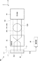
以下、実施の形態1にかかる光学測定装置100について説明する。図1に実施の形態1にかかる光学測定装置100の基本構成の上面図を示し、図2に実施の形態1にかかる光学測定装置100の基本構成の側面図を示し、図3に実施の形態1にかかる光学測定装置100の構成を模式的に示す。
Embodiment 1
The
実施の形態1にかかる光学測定装置100は、投光部10、光学系20、受光部30及び制御部40を有する。
The
投光部10は、筐体(不図示)内に配置された、光源11、拡散部12及び投光レンズ13を有する。
The
投光部10の光源11から出射された光は、拡散部12により等方的に(図3のY方向及びZ方向に)拡散され、その後、投光レンズ13により平行光となり、光学系20に向かって投射される。
The light emitted from the
以下では、平行光が通過する投光部10と光学系20との間の、測定対象物500が置かれる空間を測定空間101と称する。また、測定空間101において、平行光の進行方向と逆方向をX方向(第1の方向とも称する)、X方向に垂直な面内で互いに直交する方向をY方向(第3の方向とも称する)及びZ方向(第2の方向とも称する)とする。換言すれば、X方向は測定空間101を通過する平行光の光軸と平行な方向であり、Y方向は測定空間101を通過する平行光の厚み方向であり、Z方向は測定空間101を通過する平行光の幅方向である。
Hereinafter, a space where the
光学系20は、筐体(不図示)内に配置された第1のレンズ21、絞り22及び第2のレンズ23を有する。
The
光学系20に入射した平行光は、第1のレンズ21により集光され、絞り22の開口部を通過し、第2のレンズ23によって再び平行光となる。第2のレンズ23を透過した平行光は、受光部30に入射する。なお、測定対象物500がX方向で位置がばらついた場合に、受光部30の受光面31での像の寸法変動を避ける必要があるため、光学系20は両側テレセントリック光学系として構成されることが望ましい。
The parallel light incident on the
受光部30は、二次元イメージセンサとして構成される。二次元イメージセンサとしては、二次元CCD(Charge Coupled Device)イメージセンサ、二次元CMOS(Complementary Metal Oxide Semiconductor)イメージセンサなど、複数の画素が二次元的に配列された各種の二次元イメージセンサを用いることが可能である。受光部30の二次元イメージセンサでは、複数の画素が、その受光面31において、第2のレンズ23から入射する平行光の厚み方向(Y方向)及び幅方向(Z方向)に二次元的に配列されるように配置される。受光部30は、受光面31での受光量分布を示すアナログ信号である信号SIGを出力する。
The
また、この二次元イメージセンサは、受光面31が入射する平行光の光軸に垂直な面に対して角度θだけ傾くように、換言すれば、受光面31がZ方向を軸として角度θだけ回転するように配置される。従って、受光面31は、厳密にはZ方向と、Y方向に対してZ方向を軸として角度θだけ回転した方向とに平行な面であることが理解できる。しかしながら、角度θは比較的小さな値となるため、説明の簡略化のため、以下では受光面31においてZ方向に直交する方向を、便宜的にY方向として説明する。
Further, the two-dimensional image sensor is inclined by an angle θ with respect to a plane perpendicular to the optical axis of the parallel light incident on the
制御部40は、筐体(不図示)内に収容された、アナログ/デジタル(A/D:Analog to Digital)変換器41、中央演算処理装置(CPU:Central Processing Unit)42、メモリ43、入力装置44、出力装置45及び表示装置46を有する。
The
A/D変換器41は、受光部30から出力される信号SIGをデジタル信号に変換し、変換したデジタル信号をCPU42へ出力する。なお、この際、A/D変換器41から出力されるデジタル信号が示す受光面31の受光量分布を保持するため、図示しないメモリにデジタル信号を格納してもよい。
The A /
CPU42は、受け取ったデジタル信号に所定の信号処理を行い、測定対象物500の測定動作を行い、測定対象物500が測定空間101のいずれの位置にいるかを検出し、測定対象物のZ軸に対する傾きを検出し、又は、受光部30の受光量分布を表示可能な形式に変換したりすることが可能に構成される。CPU42での検出結果や演算結果は適宜メモリ43に書き込み可能であり、かつ、CPU42は必要に応じて所望のデータをメモリ43から読み出すことが可能である。
The
メモリ43には、制御部40の制御プログラムが記憶されていてもよい。CPU42は、メモリ43から制御プログラムを読み出すことで、自己の演算プロセスや光学測定装置100の測定動作を実行してもよい。また、図示しないが、CPU42は、制御プログラムに従って投光部10の投光動作を制御するとともに、光学測定装置100に組み込まれた各種回路での動作を制御してもよい。
The
なお、メモリ43は、制御部40によってデータの書き込み及び読み出しが行われるデータと上記の制御プログラムとが同じ記憶装置に記憶されてもよいし、同じ記憶装置内で領域を分けてデータと制御プログラムとを別個に記憶してもよいし、複数の記憶装置を設けてデータと制御プログラムとを物理的に分離して記憶してもよく、種々の記憶方法をとってもよい。メモリ43としては、ハードディスク、SSD(Solid State Drive)、フラッシュメモリなどの各種の記憶装置を用いることが可能である。
In the
入力装置44は、光学測定装置100に各種のデータやコマンドを与えるための装置であり、スイッチ、ジョイスティック、キーボード、マウス、USB(Universal Serial Bus)ポートなどの各種の入力装置を用いることができる。
The
出力装置45は、各種のデータや測定結果などを光学測定装置100の外部に出力するための装置であり、プリンタやUSBポートなどの各種の出力装置を用いることができる。
The
表示装置46は、光学測定装置100における各種の設定内容、データ、測定の進捗状況、測定結果やユーザの操作に供する情報を視認可能に表示するための装置であり、液晶ディスプレイなどの各種の表示装置を用いることができる。また、表示装置46は、CPU42から測定不可信号が与えられた場合には、測定対象物500が測定空間101から外れたことを示す情報を表示することもできる。
The
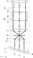
次いで、光学測定装置100の動作について、図を参照して説明する。図4〜図6は、測定空間101における焦点位置と各焦点位置における像の結像状態とを模式的に示す図である。図4〜図6では、焦点位置としてY−Z平面に平行な焦点面を考慮した。ここでは、測定空間101内のX方向で位置が異なる焦点位置として、焦点位置FP1〜FP3を想定した。焦点位置FP1は受光部30に最も近く、焦点位置FP3は受光部30から最も遠く、焦点位置FP2は焦点位置FP1と焦点位置FP3との中間とした。図4〜図6に示すように、焦点位置FP1〜FP3に対応する像が、受光部30の受光面31においてY方向に離隔している結像位置L1〜L3でそれぞれ結像するように、角度θが調整されている。なお、図2では、受光面31の結像位置L2に到達する光線を代表例として表示している。
Next, the operation of the
ここでは、上記の結像位置L1〜L3を用いて光学測定装置100の構成及び動作を説明するが、これは、受光部30における受光面31での受光量分布の位置依存性を説明するための便宜上のものに過ぎず、結像位置L1〜L3は固定的な位置ではなく、適宜選択することが可能である。また、結像位置L1〜L3の数もあくまで例示にすぎず、適宜任意の数の結像位置を設定してもよい。
Here, the configuration and operation of the
図4に示すように、測定対象物500のエッジが受光部30の受光面31に近い焦点位置FP1にある場合、測定対象物500のエッジを通過して受光面31に入射する光は、上面図において、受光面31のうちで第2のレンズ23から最も遠い結像位置L1で結像することとなる。結像位置L1以外のY方向の位置では、焦点位置FP1に対応する像が受光面31では結像しない。なお、以下では、説明の簡略化のため、測定対象物500として円柱形状の物体を想定し、円柱の軸方向をY方向と平行な方向として説明する。
As shown in FIG. 4, when the edge of the
図7に、受光部30の受光面31においてY方向及びZ方向に二次元的に配列された受光素子32と受光面31における結像位置とを示す。図7に示すように、焦点位置FP1に対応する結像位置L1は、Z方向に配列された受光素子32の列のうち、受光面31の中心からY軸のマイナス方向側に位置する列に沿った位置となることが理解できる。なお、図7に示す線OBJは、例えば円柱形状の測定対象物500をこの円柱の中心軸がY軸に平行になるように測定空間101内に配置して、X方向から観察したときにY方向に平行な円柱の輪郭、すなわち円柱の側面のエッジの像の位置を示すものであり、ここでは円柱の側面の上側(受光面31の中心からZ軸のプラス方向側)のエッジを示すものとする。
FIG. 7 shows the
焦点位置FP3に対応する結像位置L3は、Z方向に配列された受光素子32の列のうち、受光面31の中心からY軸のプラス方向側に位置する列に沿った位置となることが理解できる。
The imaging position L3 corresponding to the focal position FP3 may be a position along a column located on the positive side of the Y axis from the center of the
焦点位置FP2に対応する結像位置L2は、Z方向に配列された受光素子32の列のうち、結像位置L1と結像位置L3との中間付近の列に沿った位置となることが理解できる。
It is understood that the imaging position L2 corresponding to the focal position FP2 is a position along the middle column between the imaging position L1 and the imaging position L3 among the columns of the
結像位置L1では、焦点位置FP1に対応する像が結像しているため、結像位置L1の線OBJ付近では、円柱のエッジによって受光素子32での受光量はZ方向で暗から明へ急峻に変化する。結像位置L2では、像が結像せずに(ピンぼけ状態)光が照射されるため、結像位置L1と比べて強度が小さな光が照射される。結像位置L3では、像がよりぼけた状態(ピンぼけ状態)で光が照射されるため、結像位置L2と比べて更に強度が小さな光が照射される。
Since an image corresponding to the focal position FP1 is formed at the imaging position L1, the amount of light received by the
結像位置L1〜L3での受光素子32の受光量をZについて微分すると、それぞれの結像位置において微分値は極値をとる。ここでは、像が暗から明へ急峻に変化する場合について考慮するため、結像位置L1〜L3での受光素子32の受光量をZについて微分すると、それぞれの結像位置において微分値は極大値をとる。図8に、焦点位置FP1に対応する像が受光面31の結像位置L1で結像している場合の受光素子の受光量の微分値を示す。図8に示すように、結像位置L1では、像が結像しているため、受光量の変化が大きくなる。そのため、結像位置L1における受光量I(L1)の微分値(ΔI/ΔZ)は、極大値(ピーク値)が大きく、かつ狭い範囲で分布することとなる。これに対し、焦点位置FP1に対応する像は受光面31の結像位置L2及びL3では結像しないため(ピンボケ状態)、結像位置L2及びL3の線OBJ付近では受光素子32での受光量のZ方向の変化は無いか、または緩やかである。そのため、図8に示すように、結像位置L2における受光量I(L2)の微分値と結像位置L3における受光量I(L3)の微分値とは、結像位置L1と比べて極大値(ピーク値が小さく、かつ結像位置L1から離れるに従って緩やかな分布を示す。
When the amount of light received by the
以上より、結像位置L1での受光量I(L1)の微分値(ΔI/ΔZ)のピーク値(極大値)は、結像位置L2及びL3と比較して大きくなることが理解できる。よって、図8に示す例では、測定対象物500の焦点位置、すなわちエッジが焦点位置FP1にあるものと判断することができる。このように、受光量Iの微分値(ΔI/ΔZ)の極大値がいずれの結像位置で最大となるかを判定することで、測定対象物500の像が結像している結像位置を決定することができる。
From the above, it can be understood that the peak value (maximum value) of the differential value (ΔI / ΔZ) of the amount of received light I (L1) at the imaging position L1 is larger than the imaging positions L2 and L3. Therefore, in the example shown in FIG. 8, it can be determined that the focus position of the
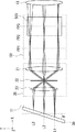
次いで、図5に示すように、測定対象物500のエッジが受光部30の受光面31に2番目に近い焦点位置FP2にある場合、焦点位置FP2に置かれた測定対象物500のエッジを通過して受光面31に入射する光は、上面図において、受光面31のうちで中央付近の位置L2で結像することとなる。結像位置L2以外のY方向の位置では、焦点位置FP2に対応する像が受光面31では結像しない(ピンボケ状態)。
Next, as shown in FIG. 5, when the edge of the measuring
結像位置L2では、焦点位置FP2に対応する像が結像しているため、結像位置L2の線OBJ付近では、円柱のエッジによって受光素子32での受光量はZ方向で暗から明へ急峻に変化する。結像位置L1及びL3では、像が結像せずに(ピンぼけ状態)光が照射されるため、結像位置L2と比べて強度が小さな光が照射される。
Since an image corresponding to the focal position FP2 is formed at the image formation position L2, the amount of light received by the
結像位置L1〜L3での受光素子32の受光量をZについて微分すると、それぞれの結像位置において微分値は極大値をとる。図9に、焦点位置FP2に対応する像が受光面31の結像位置L2で結像している場合の受光素子の受光量の微分値を示す。図9に示すように、結像位置L2では、像が結像しているため、受光量の変化が大きくなる。そのため、結像位置L2における受光量I(L2)の微分値(ΔI/ΔZ)は、極大値(ピーク値)が大きく、かつ狭い範囲で分布することとなる。これに対し、焦点位置FP2に対応する像は受光面31の結像位置L1及びL3では結像しないため(ピンボケ状態)、結像位置L1及びL3の線OBJ付近では、受光素子32での受光量のZ方向の変化は無いか、または緩やかである。そのため、図9に示すように、結像位置L1における受光量I(L1)の微分値と結像位置L3における受光量I(L3)の微分値とは、結像位置L2と比べて極大値(ピーク値)が小さく、かつ結像位置L1よりも緩やかな分布を示す。
When the amount of light received by the
以上より、結像位置L2での受光量I(L2)の微分値(ΔI/ΔZ)の極大値は、結像位置L1及びL3と比較して大きくなることが理解できる。よって、図9に示す例では、測定対象物500の焦点位置、すなわちエッジが焦点位置FP2にあるものと判断することができる。
From the above, it can be understood that the maximum value of the differential value (ΔI / ΔZ) of the received light amount I (L2) at the imaging position L2 is larger than those at the imaging positions L1 and L3. Therefore, in the example shown in FIG. 9, it can be determined that the focus position of the
次いで、図6に示すように、測定対象物500のエッジが受光部30の受光面31から最も遠い焦点位置FP3にある場合、焦点位置FP3に置かれた測定対象物500のエッジを通過して受光面31に入射する光は、上面図において、受光面31のうちで第2のレンズ23から最も近い位置L3で結像することとなる。結像位置L3以外のY方向の位置では、焦点位置FP3に対応する像が受光面31では結像しない(ピンボケ状態)。
Next, as shown in FIG. 6, when the edge of the
結像位置L3では、焦点位置FP3に対応する像が結像しているため、結像位置L3の線OBJ付近では、円柱のエッジによって受光素子32での受光量はZ方向で暗から明へ急峻に変化する。結像位置L1及びL2では、像が結像せずに(ピンぼけ状態)光が照射されるため、結像位置L3と比べて強度が小さな光が照射される。
Since an image corresponding to the focal position FP3 is formed at the imaging position L3, the amount of light received by the
結像位置L1〜L3での受光素子32の受光量をZについて微分すると、それぞれの結像位置において微分値は極大値をとる。図10に、焦点位置FP3に対応する像が受光面31の結像位置L3で結像している場合の受光素子の受光量の微分値を示す。図10に示すように、結像位置L3では、像が結像しているため、受光量の変化が大きくなる。そのため、結像位置L3における受光量I(L3)の微分値(ΔI/ΔZ)は、極大値(ピーク値)が大きく、かつ狭い範囲で分布することとなる。これに対し、焦点位置FP3に対応する像は受光面31の結像位置L1及びL2では結像しないため(ピンボケ状態)、結像位置L1及びL2の線OBJ付近では、受光素子32での受光量のZ方向の変化は無いか、または緩やかである。そのため、図10に示すように、結像位置L1における受光量I(L1)の微分値と結像位置L2における受光量I(L2)の微分値とは、結像位置L2と比べて極大値(ピーク値)が小さく、かつ結像位置L3から離れるに従って緩やかな分布を示す。
When the amount of light received by the
以上より、結像位置L3での受光量I(L3)の微分値(ΔI/ΔZ)の極大値は、結像位置L1及びL2と比較して大きくなることが理解できる。よって、図10に示す例では、測定対象物500の焦点位置、すなわちエッジが焦点位置FP3にあるものと判断することができる。
From the above, it can be understood that the maximum value of the differential value (ΔI / ΔZ) of the received light amount I (L3) at the imaging position L3 is larger than those at the imaging positions L1 and L2. Therefore, in the example shown in FIG. 10, it can be determined that the focus position of the
以上説明したように、受光面31において、Y方向のいずれの位置で受光量の微分値の極大値が最大となるかによって、焦点位置のX方向の位置、すなわち被測定物が測定空間101のどの位置に配置されているかを検出することができる。
As described above, the position in the X direction of the focal position, that is, the object to be measured is determined in the
また、測定対象物500の概略形状がわかっている場合には、測定対象物500によっては、結像位置L1〜L3の全てで像が結像する場合がある。この場合、結像した像に対応する測定対象物500のエッジが概ね直線である場合には、測定対象物500のZ方向を回転軸とする回転量を検出することも可能である。この場合、結像位置L1〜L3では、受光量のZ方向の微分値がそれぞれ極大値をとるが、これらの極大値が所定の範囲内に収まっている場合に結像位置L1〜L3の全てで像が結像していると判定することが可能である。
In addition, when the schematic shape of the
本構成では、二次元イメージセンサを1つ用いるだけでよいので、複数のイメージセンサを用いて同様の動作を行う光学測定装置と比べて装置構成を簡素化できるので、製造コストの削減、メンテナンス性及び信頼性の向上、光学部品の調整の簡易化を実現することができる。また、複数のイメージセンサに光を分配する必要がないので、ビームスプリッタやハーフミラーを配置せずともよいので、部品点数を削減でき、かつ、各イメージセンサに入射する光量の減少を防止できる。その結果、測定精度の向上、測定の高速化を図ることができる。また、ハーフミラーの使用を回避できるので、これによるゴースト発生の懸念を解消することもできる。 In this configuration, since only one two-dimensional image sensor is used, the device configuration can be simplified compared to an optical measurement device that performs the same operation using a plurality of image sensors, thereby reducing manufacturing costs and maintainability. Further, it is possible to improve the reliability and simplify the adjustment of the optical components. Further, since it is not necessary to distribute light to a plurality of image sensors, it is not necessary to arrange a beam splitter or a half mirror, so that the number of parts can be reduced and a decrease in the amount of light incident on each image sensor can be prevented. As a result, measurement accuracy can be improved and measurement speed can be increased. Further, since the use of the half mirror can be avoided, the concern about the occurrence of ghost due to this can be solved.
実施の形態2
以下、実施の形態2にかかる光学測定装置について説明する。上述の実施の形態1では、円柱形状の測定対象物500は、軸方向がY方向に平行であるものとしたが、測定対象物500を測定空間101に置くときの状態によっては、円柱の軸方向がY方向と平行ではなくなることが考え得る。図11に、実施の形態2にかかる光学測定装置での測定対象物の配置を示す。本実施の形態では、図11に示すように、測定対象物500のエッジが焦点位置FP1〜FP3に位置するように、測定対象物500はZ方向を軸として角度θだけ回転している。また、測定対象物500の軸は、Y方向に対して角度φだけ回転している。
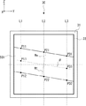
The optical measurement apparatus according to the second embodiment will be described below. In the first embodiment described above, the
この場合、測定対象物500の像が受光部30の受光面31上に結像する。図12に、実施の形態2にかかる光学測定装置において受光面に結像する測定対象物の像を示す図である。図12では、像の暗部を符号501で示している。図12に示すように、測定空間101において測定対象物500の軸方向がY方向に対して角度φだけ回転しているので、受光面31上の像もY方向に対して角度φだけ傾いている。この状態で測定対象物500のZ方向の寸法を測定してしまうと、傾きによって、実際の測定対象物500の寸法よりも長い寸法Waが測定されてしまう。
In this case, an image of the
そこで、本実施の形態では、像が結像したときの受光面31上での受光量分布を用いて傾きを補正し、測定対象物500の寸法を正確に求める方法について検討する。なお、図12では、受光素子32が配列されている領域を、受光領域33として表示している。
In view of this, in the present embodiment, a method of correcting the inclination using the received light amount distribution on the
まず、光学測定装置100は、像が結像したときの受光面31上での受光量分布を測定し、CPU42は測定した受光量分布をメモリ43に書き込む。
First, the
CPU42は、結像位置L1近傍の受光素子32のZ方向の列(例えば、2列程度)が検出した受光量データをメモリ43から読み込み、受光量が急峻に変化する端点P11と端点P12とを算出する。なお、言うまでもないが、端点P11と端点P12とは、Z方向に平行な線上に位置する点である。その後、CPU42は、端点P11と端点P12との間の中点P13を算出する。
The
CPU42は、結像位置L3近傍の受光素子32のZ方向の列(例えば、2列程度)が検出した受光量データをメモリ43から読み込み、受光量が急峻に変化する端点P31と端点P32とを算出する。なお、言うまでもないが、端点P31と端点P32とは、Z方向に平行な線上に位置する点である。その後、CPU42は、端点P31と端点P32との間の中点P33を算出する。
The
CPU42は、中点P13と中点P33とを結ぶ線とY方向との傾き、すなわち角度φを算出する。
The
CPU42は、結像位置L2近傍の受光素子32のZ方向の列(例えば、4列程度)が検出した受光量データをメモリ43から読み込み、受光量が急峻に変化する端点P21と端点P22とを算出する。なお、言うまでもないが、端点P21と端点P22とは、Z方向に平行な線上に位置する点である。
The
その後、CPU42は、端点P21と端点P22との間のZ方向の寸法Waを算出する。そして、寸法Waにcosφを乗じることで、測定対象物500の正確な寸法Wtを算出することができる。
Thereafter, the
以上、本構成によれば、イメージセンサの受光面における像に傾きが生じた場合でも、受光面での受光量分布を用いて像の傾きを検出し、傾き補正を行って測定対象物500の寸法を正確に検出することができる。 As described above, according to this configuration, even when an image on the light receiving surface of the image sensor is tilted, the tilt of the image is detected by using the received light amount distribution on the light receiving surface, and the tilt of the image is measured. The dimensions can be detected accurately.
また、本構成によれば、受光面での受光量分布データのうち一部だけを用いて傾き補正を行うため、正確な寸法測定を正確かつ高速に行うことが可能となる。 Further, according to this configuration, since the inclination correction is performed using only a part of the received light amount distribution data on the light receiving surface, it is possible to perform accurate dimension measurement accurately and at high speed.
なお、本実施の形態では、単一の測定対象物500の像が受光部30の受光面31上に結像し、像の暗部501の幅を測定する例について示したが、これは例示に過ぎない。例えば、2つの測定対象物の像の間に存在する明部の幅についても、同様の補正を行って測定できることはいうまでもない。
In the present embodiment, an example in which an image of a
その他の実施の形態
なお、本発明は上記実施の形態に限られたものではなく、趣旨を逸脱しない範囲で適宜変更することが可能である。例えば、結像位置L1〜L3での結像状態と様々な形状を有する測定対象物との関係を予め把握しておくことで、結像位置L1〜L3での結像を観察することで、結像位置L1〜L3の一部又は全部で像が結像しない場合でも、測定対象物の回転量を検出できる構成とすることも可能である。
Other Embodiments The present invention is not limited to the above-described embodiments, and can be appropriately changed without departing from the spirit of the present invention. For example, by grasping in advance the relationship between the imaging state at the imaging positions L1 to L3 and the measurement object having various shapes, by observing the imaging at the imaging positions L1 to L3, Even when an image is not formed at some or all of the imaging positions L1 to L3, it is possible to adopt a configuration that can detect the amount of rotation of the measurement object.
また、結像位置L1〜L3の一部又は全部における受光量の微分値のZ座標を特定することで、測定空間101における測定対象物500の位置が検出できることは、言うまでもない。
It goes without saying that the position of the
上述の光学測定装置には、例えば他の制御装置や表示装置などを接続することで、光学測定装置の外部から測定動作を制御する構成とすることも可能である。 For example, another control device or a display device may be connected to the optical measurement device described above to control the measurement operation from the outside of the optical measurement device.
上述の光学測定装置の光学系は例示に過ぎず、光源から投射され、測定空間を通過した平行光の光軸に対して二次元イメージセンサを傾けて配置できる限り、他の構成の光学系を用いてもよい。 The optical system of the above-described optical measurement device is merely an example, and other optical systems having other configurations may be used as long as the two-dimensional image sensor can be disposed with an inclination relative to the optical axis of the parallel light projected from the light source and passing through the measurement space. It may be used.
上記の制御部の構成は例示に過ぎず、上述の実施の形態と同様の動作を実現できる限り、他の構成としてもよい。 The configuration of the control unit described above is merely an example, and other configurations may be employed as long as the same operation as that of the above-described embodiment can be realized.
上述の実施の形態では、受光部30を構成する二次元イメージセンサがアナログ信号である信号SIGを出力し、制御部40のA/D変換器が信号SIGをデジタル信号に変換し、変換後のデジタル信号がCPU42に入力される構成について説明したが、これは例示に過ぎない。例えば、受光部30を構成する二次元イメージセンサ内にA/D変換器変換器を設け、検出結果を示すアナログ信号を二次元イメージセンサ内でアナログ/デジタル変換し、変換後のアナログ信号を制御部40のCPU42に与える構成としてもよい。これにより、制御部の構成を簡素化し、コストダウンと実装面積の縮小化を図ることが可能となる。
In the above-described embodiment, the two-dimensional image sensor that constitutes the
上述の実施の形態では、像が暗から明へ急峻に変化する場合について考慮し、受光素子32の受光量をZについて微分し、微分値が極大値をとる位置を検出する例について説明した。これに対し、像が明から暗へ急峻に変化する場合について考慮したときには、受光素子32の受光量をZについて微分し、微分値が極小値をとる位置を検出し、そして極小値が最小となる受光面におけるY方向の位置を検出してもよい。すなわち、微分値が極大値及び極小値を含む極値を検出し、検出した極値の絶対値が受光面のY方向のいずれの位置で最大になるかを検出できればよい。
In the above-described embodiment, an example in which the amount of light received by the
また、受光部30を構成する二次元イメージセンサセンサの回転角度θを調節することで、例えば焦点位置FP1と焦点位置FP3との間の距離が可変となる。これにより、角度θを大きくすることで、測定空間101内のX軸方向の焦点位置観測範囲を広くすることができる。角度θが0の場合は、焦点位置FP1及びFP3は、焦点位置FP2と一致する。この場合、結像位置L1〜L3でほぼ同等の微分値が検出されるので、検出した微分値を平均する事でより精度が高いエッジ検出が可能となる。このように、適宜角度θを調整することで、所望の焦点位置観測範囲やエッジ検出を使い分けることも可能である。角度θの調整は、例えば、受光部30に連結されたアクチュエータ(不図示)などを制御部40が駆動することで実現するこができる。
Further, by adjusting the rotation angle θ of the two-dimensional image sensor constituting the
10 投光部
11 光源
12 拡散部
13 投光レンズ
20 光学系
21 第1のレンズ
22 絞り
23 第2のレンズ
30 受光部
31 受光面
32 受光素子
33 受光領域
40 制御部
41 A/D変換器
42 CPU
43 メモリ
44 入力装置
45 出力装置
46 表示装置
100 光学測定装置
101 測定空間
500 測定対象物
FP1〜FP3 焦点位置
L1〜L3 結像位置
SIG 信号
DESCRIPTION OF
43
Claims (8)
受光面に投射される光の二次元分布を示す信号を出力する受光部と、
前記測定空間を通過する光を前記受光部の前記受光面へ導く光学系と、
前記受光部から出力される前記信号に基づいて前記第1の方向における前記測定対象物の位置を検出する制御部と、を備え、
前記受光部の前記受光面は、前記受光面に投射される光の投射方向に対して、前記第1の方向と直交する第2の方向を軸として所定角度だけ傾いており、
前記制御部は、前記受光部から出力される前記信号に基づいて、前記光の二次元分布において前記第2の方向で光量が所定量変化している箇所を検出し、検出した箇所の前記受光面において前記第2の方向と交差する第3の方向での位置を検出し、前記検出した位置に基づいて、前記測定対象物が配置された前記測定空間内の前記第1の方向における位置を検出する、
光学測定装置。 A light projecting unit that projects light in parallel to the first direction to a measurement space in which the measurement object is disposed;
A light receiving unit that outputs a signal indicating a two-dimensional distribution of light projected on the light receiving surface;
An optical system for guiding light passing through the measurement space to the light receiving surface of the light receiving unit;
A control unit that detects the position of the measurement object in the first direction based on the signal output from the light receiving unit;
The light receiving surface of the light receiving unit is inclined by a predetermined angle with respect to a projection direction of light projected on the light receiving surface, with a second direction orthogonal to the first direction as an axis,
The control unit detects, based on the signal output from the light receiving unit, a portion where the light amount is changed by a predetermined amount in the second direction in the two-dimensional distribution of the light, and the light reception of the detected portion. A position in a third direction that intersects the second direction on the surface is detected, and a position in the first direction in the measurement space in which the measurement object is arranged is determined based on the detected position. To detect,
Optical measuring device.
前記受光部から出力される前記信号に基づいて、前記光の二次元分布において前記第2の方向における光量の微分値分布を、前記第3の方向の複数の箇所について検出し、
前記微分値分布の極値の絶対値が最大となる前記第3の方向での位置を検出し、
検出した前記第3の方向での位置に基づいて、前記測定対象物が配置された前記測定空間内の前記第1の方向における位置を検出する、
請求項1に記載の光学測定装置。 The controller is
Based on the signal output from the light receiving unit, the differential value distribution of the light quantity in the second direction in the two-dimensional distribution of the light is detected for a plurality of locations in the third direction,
Detecting the position in the third direction where the absolute value of the extreme value of the differential value distribution is maximum;
Based on the detected position in the third direction, a position in the first direction in the measurement space where the measurement object is arranged is detected.
The optical measuring device according to claim 1.
請求項2に記載の光学測定装置。 When the absolute value of the extreme value of the differential value distribution of the light amount in the second direction detected at a plurality of locations in the third direction falls within a predetermined range, the measurement object is in the second direction. Is determined to be rotated by the predetermined angle about the axis,
The optical measuring device according to claim 2.
請求項1乃至3のいずれか一項に記載の光学測定装置。 The optical system is configured as a double-sided telecentric optical system,
The optical measuring device according to any one of claims 1 to 3.
請求項1乃至4のいずれか一項に記載の光学測定装置。 The light receiving unit is a two-dimensional image sensor having a plurality of light receiving elements arranged two-dimensionally in the second direction and the third direction.
The optical measuring device according to any one of claims 1 to 4.
前記受光面で前記第2の方向に離隔して並んだ像の2つのエッジを検出し、
前記2つのエッジに基づいて、前記2つのエッジの前記第3の方向に対する傾きを検出し、
前記2つのエッジ間の前記第2の方向の距離を、検出した前記傾きに基づいて補正することで、前記2つのエッジ間の距離を算出する、
請求項1乃至5のいずれか一項に記載の光学測定装置。 The controller is
Detecting two edges of the image spaced apart in the second direction on the light receiving surface;
Detecting a slope of the two edges with respect to the third direction based on the two edges;
Calculating the distance between the two edges by correcting the distance in the second direction between the two edges based on the detected inclination;
The optical measuring device according to any one of claims 1 to 5.
前記2つのエッジの一方は2つの前記測定対象物の一方の像のエッジに対応し、前記2つのエッジの他方は2つの前記測定対象物の他方の像のエッジに対応する、
請求項6に記載の光学測定装置。 The two edges correspond to one edge of the image of the measurement object, or
One of the two edges corresponds to an edge of one image of the two measurement objects, and the other of the two edges corresponds to an edge of the other image of the two measurement objects;
The optical measuring device according to claim 6.
請求項6又は7に記載の光学測定装置。 The control unit calculates a distance between the two edges by multiplying a distance in the second direction between the two edges by a cosine of an angle indicating the detected inclination.
The optical measuring device according to claim 6 or 7.
Priority Applications (4)
| Application Number | Priority Date | Filing Date | Title |
|---|---|---|---|
| JP2017128275A JP6862303B2 (en) | 2017-06-30 | 2017-06-30 | Optical measuring device |
| EP18176744.3A EP3421928B1 (en) | 2017-06-30 | 2018-06-08 | Optical measuring device |
| US16/020,029 US10724847B2 (en) | 2017-06-30 | 2018-06-27 | Optical measuring device |
| CN201810706172.9A CN109211106B (en) | 2017-06-30 | 2018-06-29 | Optical measuring device |
Applications Claiming Priority (1)
| Application Number | Priority Date | Filing Date | Title |
|---|---|---|---|
| JP2017128275A JP6862303B2 (en) | 2017-06-30 | 2017-06-30 | Optical measuring device |
Publications (2)
| Publication Number | Publication Date |
|---|---|
| JP2019012006A true JP2019012006A (en) | 2019-01-24 |
| JP6862303B2 JP6862303B2 (en) | 2021-04-21 |
Family
ID=62597338
Family Applications (1)
| Application Number | Title | Priority Date | Filing Date |
|---|---|---|---|
| JP2017128275A Active JP6862303B2 (en) | 2017-06-30 | 2017-06-30 | Optical measuring device |
Country Status (4)
| Country | Link |
|---|---|
| US (1) | US10724847B2 (en) |
| EP (1) | EP3421928B1 (en) |
| JP (1) | JP6862303B2 (en) |
| CN (1) | CN109211106B (en) |
Families Citing this family (1)
| Publication number | Priority date | Publication date | Assignee | Title |
|---|---|---|---|---|
| JP7319083B2 (en) * | 2019-04-26 | 2023-08-01 | 株式会社キーエンス | optical displacement meter |
Citations (5)
| Publication number | Priority date | Publication date | Assignee | Title |
|---|---|---|---|---|
| JPH06294621A (en) * | 1993-04-07 | 1994-10-21 | Kobe Steel Ltd | Optical profile measuring equipment |
| JPH11132748A (en) * | 1997-10-24 | 1999-05-21 | Hitachi Ltd | Multifocal simultaneous detection device, three-dimensional shape detection device, appearance inspection device, and method thereof |
| JP2005504305A (en) * | 2001-09-21 | 2005-02-10 | ビジコン インスペクション テクノロジーズ エルエルシー | 3D scanning camera |
| JP2014006134A (en) * | 2012-06-25 | 2014-01-16 | Keyence Corp | Optical measurement device |
| US20140043610A1 (en) * | 2012-08-07 | 2014-02-13 | Carl Zeiss Industrielle Messtechnik Gmbh | Apparatus for inspecting a measurement object with triangulation sensor |
Family Cites Families (18)
| Publication number | Priority date | Publication date | Assignee | Title |
|---|---|---|---|---|
| US3853406A (en) * | 1973-06-08 | 1974-12-10 | Zygo Corp | Differential optical noncontacting diameter gauge utilizing a pair of linearly scanning light beams sequentially scanning the test piece |
| US3856412A (en) * | 1973-06-08 | 1974-12-24 | Zygo Corp | Optical noncontacting gauge |
| US4105925A (en) * | 1977-03-14 | 1978-08-08 | General Motors Corporation | Optical object locator |
| JPS603502A (en) * | 1983-06-20 | 1985-01-09 | Toyota Motor Corp | Non-contacting type distance measuring method |
| DE4225319A1 (en) * | 1992-07-31 | 1994-02-03 | Trumpold Harry Prof Dr Ing Hab | Absolute distance or angle measurement system - has linear CCD image scanner aligned orthogonally to direction of movement of bar=code carrier, having central aperiodic bar=code at acute angle to movement direction |
| JPH08247726A (en) * | 1995-03-13 | 1996-09-27 | Omron Corp | Dimension measuring device |
| JP2004058627A (en) * | 2002-07-31 | 2004-02-26 | Canon Inc | Droplet measuring method and device therefor |
| US20070236685A1 (en) * | 2006-03-30 | 2007-10-11 | Hong Kong Applied Science And Technology Research Institute Co., Ltd. | Optical tilt sensor |
| EP2136178A1 (en) * | 2007-04-05 | 2009-12-23 | Nikon Corporation | Geometry measurement instrument and method for measuring geometry |
| JP4719284B2 (en) * | 2008-10-10 | 2011-07-06 | トヨタ自動車株式会社 | Surface inspection device |
| JP2010145468A (en) * | 2008-12-16 | 2010-07-01 | Canon Inc | Height detection device and toner height detection apparatus using the same |
| JP2010249604A (en) * | 2009-04-14 | 2010-11-04 | Mitsutoyo Corp | Optical measuring apparatus, optical measuring method, and optical measurement processing program |
| JP5261314B2 (en) * | 2009-07-31 | 2013-08-14 | シャープ株式会社 | Eccentricity measuring apparatus and eccentricity measuring method |
| CN102003950A (en) * | 2010-10-26 | 2011-04-06 | 西安昂科光电有限公司 | Device and method for measuring surface flatness of light wave array surface or optical reflecting surface |
| JP6009753B2 (en) * | 2011-10-26 | 2016-10-19 | 株式会社トプコン | Image measuring device |
| CN204831226U (en) * | 2015-08-14 | 2015-12-02 | 西安工业大学 | A optics light path for detection lens center is inclined to one side and optical detection device thereof |
| CN105737759B (en) * | 2016-02-24 | 2018-06-29 | 中国科学院上海应用物理研究所 | A kind of long-range profile measuring device |
| JP2018124167A (en) * | 2017-01-31 | 2018-08-09 | オムロン株式会社 | Inclination measuring device |
-
2017
- 2017-06-30 JP JP2017128275A patent/JP6862303B2/en active Active
-
2018
- 2018-06-08 EP EP18176744.3A patent/EP3421928B1/en active Active
- 2018-06-27 US US16/020,029 patent/US10724847B2/en active Active
- 2018-06-29 CN CN201810706172.9A patent/CN109211106B/en active Active
Patent Citations (5)
| Publication number | Priority date | Publication date | Assignee | Title |
|---|---|---|---|---|
| JPH06294621A (en) * | 1993-04-07 | 1994-10-21 | Kobe Steel Ltd | Optical profile measuring equipment |
| JPH11132748A (en) * | 1997-10-24 | 1999-05-21 | Hitachi Ltd | Multifocal simultaneous detection device, three-dimensional shape detection device, appearance inspection device, and method thereof |
| JP2005504305A (en) * | 2001-09-21 | 2005-02-10 | ビジコン インスペクション テクノロジーズ エルエルシー | 3D scanning camera |
| JP2014006134A (en) * | 2012-06-25 | 2014-01-16 | Keyence Corp | Optical measurement device |
| US20140043610A1 (en) * | 2012-08-07 | 2014-02-13 | Carl Zeiss Industrielle Messtechnik Gmbh | Apparatus for inspecting a measurement object with triangulation sensor |
Also Published As
| Publication number | Publication date |
|---|---|
| US20190003821A1 (en) | 2019-01-03 |
| US10724847B2 (en) | 2020-07-28 |
| JP6862303B2 (en) | 2021-04-21 |
| CN109211106A (en) | 2019-01-15 |
| EP3421928B1 (en) | 2019-09-25 |
| EP3421928A1 (en) | 2019-01-02 |
| CN109211106B (en) | 2021-09-07 |
Similar Documents
| Publication | Publication Date | Title |
|---|---|---|
| JP5095644B2 (en) | Image measuring apparatus and computer program | |
| TWI740237B (en) | Optical phase profilometry system | |
| JP6620869B2 (en) | Calibration method, calibration apparatus, and program | |
| JP4839827B2 (en) | 3D measuring device | |
| EP2138803A1 (en) | Jig for measuring an object shape and method for measuring a three-dimensional shape | |
| JPWO2017183582A1 (en) | Optical property measuring device | |
| JP2020180916A (en) | Optical displacement meter | |
| JP2011196732A (en) | Method for measuring wavefront aberration and device of the same | |
| JP2012026816A (en) | Dimension measuring method and device | |
| JP2009008483A (en) | Measuring method of surface to be measured | |
| JP2015108582A (en) | Three-dimensional measurement method and device | |
| JP6862303B2 (en) | Optical measuring device | |
| JP4846295B2 (en) | Three-dimensional coordinate measuring apparatus and method | |
| CN114025913B (en) | Measuring device | |
| JP7277267B2 (en) | Measuring device, imaging device, measuring system and program | |
| JP2009264898A (en) | Workpiece position/attitude measurement method and measuring device | |
| JPH085344A (en) | Three-dimensional shape input device | |
| JP5531071B2 (en) | Image measuring apparatus and computer program | |
| JP7817398B2 (en) | Distance measuring device | |
| JP2017125707A (en) | Measurement method and measurement device | |
| JP2014197004A (en) | Image measurement device | |
| JP2014115179A (en) | Measuring device, document camera and measuring method | |
| KR20230169222A (en) | Board metrology device and board measurement method | |
| JP7648652B2 (en) | Three-dimensional measurement device and three-dimensional measurement program | |
| JP3437479B2 (en) | Birefringence measurement device |
Legal Events
| Date | Code | Title | Description |
|---|---|---|---|
| A621 | Written request for application examination |
Free format text: JAPANESE INTERMEDIATE CODE: A621 Effective date: 20200521 |
|
| A977 | Report on retrieval |
Free format text: JAPANESE INTERMEDIATE CODE: A971007 Effective date: 20210317 |
|
| TRDD | Decision of grant or rejection written | ||
| A01 | Written decision to grant a patent or to grant a registration (utility model) |
Free format text: JAPANESE INTERMEDIATE CODE: A01 Effective date: 20210330 |
|
| A61 | First payment of annual fees (during grant procedure) |
Free format text: JAPANESE INTERMEDIATE CODE: A61 Effective date: 20210331 |
|
| R150 | Certificate of patent or registration of utility model |
Ref document number: 6862303 Country of ref document: JP Free format text: JAPANESE INTERMEDIATE CODE: R150 |
|
| R250 | Receipt of annual fees |
Free format text: JAPANESE INTERMEDIATE CODE: R250 |