JP2019072902A - Preform, plastic bottle and method for producing the same - Google Patents
Preform, plastic bottle and method for producing the same Download PDFInfo
- Publication number
- JP2019072902A JP2019072902A JP2017199943A JP2017199943A JP2019072902A JP 2019072902 A JP2019072902 A JP 2019072902A JP 2017199943 A JP2017199943 A JP 2017199943A JP 2017199943 A JP2017199943 A JP 2017199943A JP 2019072902 A JP2019072902 A JP 2019072902A
- Authority
- JP
- Japan
- Prior art keywords
- preform
- injection
- intermediate layer
- layer
- injected
- Prior art date
- Legal status (The legal status is an assumption and is not a legal conclusion. Google has not performed a legal analysis and makes no representation as to the accuracy of the status listed.)
- Pending
Links
Images





Classifications
-
- B—PERFORMING OPERATIONS; TRANSPORTING
- B29—WORKING OF PLASTICS; WORKING OF SUBSTANCES IN A PLASTIC STATE IN GENERAL
- B29C—SHAPING OR JOINING OF PLASTICS; SHAPING OF MATERIAL IN A PLASTIC STATE, NOT OTHERWISE PROVIDED FOR; AFTER-TREATMENT OF THE SHAPED PRODUCTS, e.g. REPAIRING
- B29C45/00—Injection moulding, i.e. forcing the required volume of moulding material through a nozzle into a closed mould; Apparatus therefor
- B29C45/17—Component parts, details or accessories; Auxiliary operations
- B29C45/26—Moulds
- B29C45/263—Moulds with mould wall parts provided with fine grooves or impressions, e.g. for record discs
-
- B—PERFORMING OPERATIONS; TRANSPORTING
- B29—WORKING OF PLASTICS; WORKING OF SUBSTANCES IN A PLASTIC STATE IN GENERAL
- B29C—SHAPING OR JOINING OF PLASTICS; SHAPING OF MATERIAL IN A PLASTIC STATE, NOT OTHERWISE PROVIDED FOR; AFTER-TREATMENT OF THE SHAPED PRODUCTS, e.g. REPAIRING
- B29C45/00—Injection moulding, i.e. forcing the required volume of moulding material through a nozzle into a closed mould; Apparatus therefor
- B29C45/17—Component parts, details or accessories; Auxiliary operations
- B29C45/26—Moulds
- B29C45/261—Moulds having tubular mould cavities
Landscapes
- Engineering & Computer Science (AREA)
- Manufacturing & Machinery (AREA)
- Mechanical Engineering (AREA)
- Injection Moulding Of Plastics Or The Like (AREA)
- Blow-Moulding Or Thermoforming Of Plastics Or The Like (AREA)
Abstract
Description
本発明は、プリフォーム、プラスチックボトル及びプリフォームの製造方法に関し、より詳細には、多層のプラスチックボトル、プリフォーム、及びプリフォームの製造方法に関する。 The present invention relates to preforms, plastic bottles and methods of making preforms, and more particularly, to multilayer plastic bottles, preforms and methods of making preforms.
飲料等が充填される容器として、プラスチックボトル、中でも、PET(PolyEthylene Terephthalate)ボトルが多く用いられる。そして、PETボトルの基材のポリエチレンテレフタレートでは不足する機能を補うための別の材料が積層された多層ボトルも市場の広がりを見せている。 Plastic bottles, in particular, PET (PolyEthylene Terephthalate) bottles are often used as containers filled with beverages and the like. And the multilayer bottle on which another material is laminated to compensate for the function which is lacking in the polyethylene terephthalate of the base material of the PET bottle is also showing the market spread.
特許文献1には、エチレンテレフタレート系ポリエステル樹脂から成る内外層、及び少なくとも低結晶性エチレンテレフタレート系ポリエステル樹脂及び芳香族ポリアミド系ガスバリア性樹脂から成る中間層を少なくとも1層有し、低結晶性エチレンテレフタレート系ポリエステル樹脂がジカルボン酸成分中7.5〜15 モル%のイソフタル酸を含有すると共に、多層構造が形成されている部分のヘイズが5 %以上である多層プリフォームが開示されている。更に、特許文献1には、多層プリフォームを二軸延伸ブロー成形してなり、胴部のヘイズが3 %以下である多層延伸ブロー成形容器が開示されている。
特許文献1によれば、内外層を結晶性のエチレンテレフタレート系ポリエステル樹脂から構成することにより、延伸特性に劣る低結晶性ポリエステル樹脂を用いた中間層に均一な延伸倍率を付与することが可能になり、優れた機械的強度を有する多層延伸ブロー成形容器を提供できるとされている。更に、特許文献1によれば、バリア性中間層が低結晶性ポリエステル樹脂が連続相、芳香族ポリアミド樹脂系ガスバリア性樹脂が分散相の海島分散構造になることにより、内外層及びバリア性中間層の層間接着性を向上させることができるとされている。そして、特許文献1の多層プリフォームから得られる多層延伸ブロー容器は落下衝撃等による層間剥離(デラミネーション)なども防止することができるとされている。
According to
特許文献1には、容器のガスバリア性を確保するために、延伸の際に高倍率で延伸される多層プリフォームの少なくとも容器胴部となるべき部分にバリア性中間層が形成されている必要があるとの記載がある。しかしながら、特許文献1は、容器の口部となるべき部分に耐熱材料を用いた中間層が形成される構成は記載されていない。
In
特許文献2には、ポリエチレンテレフタレート樹脂製容器の口部を加熱処理することにより結晶化させる方法として、白化処理を口部の上部と口部の側面部に対し分割して行い、口部上部を白化処理した後、口側面部を白化処理するポリエチレンテレフタレート樹脂製容器の口部の白化方法が開示されている。
In
また特許文献3には、長期にわたり形状を保持し、非常な高温度に加熱され又は加圧されても強度特性を保持する新規な結晶性熱可塑性ポリマー製の容器を提供するため、 結晶性熱可塑性ポリエステル樹脂からなり、口部、これに続く首部、胴部及び底部を有し、少くとも上記胴部は二軸延伸により配向され透明で内部応力が解放され、かつ、口部が実質的に無配向に結晶化されて乳白色化されていることを特徴とする強化耐熱性容器が開示されている。
特許文献4では、アウターリング、コンタクトリングおよびインナーリングを有するネジ込み式のキャップを口部に装着することにより密閉することが可能な、口部に結晶化処理が施されていないプラスチック製容器であって、
前記口部の外周にネジが形成され、
前記ネジ上端と前記口部の天面との間の少なくとも一部に、天面に近づくほど外径が曲線を描くような形状で増大するアンダーカット部を設けたプラスチック製容器であり、
前記プラスチック製容器の密閉が、(イ)前記口部のネジ上端と前記口部の天面との間の、前記キャップのアウターリングとの接触部であるアウターリング接触部、(ロ)前記口部の天面と前記キャップのコンタクトリングとの接触部であるコンタクトリング接触部、および(ハ)前記口部内側と前記キャップのインナーリングとの接触部であるインナーリング接触部において、前記口部と前記キャップとが密着することによって実現されることを特徴とする、プラスチック製容器が開示されている。
A screw is formed on the outer periphery of the mouth,
It is a plastic container provided with an undercut portion in which the outer diameter increases in a curved shape as it approaches the top surface at least at a part between the screw upper end and the top surface of the opening.
An outer ring contact portion which is a contact portion between the screw upper end of the opening and the top surface of the opening, which is a contact portion with the outer ring of the cap, (b) the opening A contact ring contact portion which is a contact portion between a top surface of the portion and a contact ring of the cap, and (c) an inner ring contact portion which is a contact portion between the inner side of the mouth portion and an inner ring of the cap A plastic container is disclosed, characterized in that it is realized by the close contact between the and the cap.
そもそも、このように従来ペットボトル容器の口栓部を結晶化することにより、口栓部に耐熱性を持たせることが行われている。従来飲料を高温にし、充填することで殺菌する方法などが良く行われており、口部より高温となっている飲料や液体を充填するため、口栓部が高温になりやすく、変形しやすいという問題があり、このため、口栓部の結晶化が行われる。口部を結晶化することで、成形後のプラスチックボトルが耐熱性を持ち、変形しにくくなり、キャップとのかみ合わせが悪くなることがなく、従って液漏れなどが起こりにくくなるという利点があるからである。しかしながら、口部を結晶化するためには、例えば特許文献2のように、ポリエチレンテレフタレート樹脂製容器の口部を加熱処理することにより結晶化させるために、口部の上部と側面部を分割して白化処理する技術を必要としたり、特許文献3のような方法を用いてブロー成形することが必要とされる。またこのような方法を用いたとしても、結晶化された口部を有するペットボトル容器等の作成にかかるコストがかなり大きいという問題があった。
In the first place, conventionally, the plug part is made to have heat resistance by crystallizing the plug part of the conventional plastic bottle container as described above. Conventionally, the method of sterilizing by heating the beverage at high temperature and filling it is well performed, and it is said that the plug part is likely to be at high temperature and easily deformed because it is filled with the beverage or liquid that is at a higher temperature than the mouth. There is a problem that causes crystallization of the plug. By crystallizing the mouth, the plastic bottle after molding has heat resistance, is less likely to be deformed, and there is no advantage that the engagement with the cap does not deteriorate, so that there is an advantage that liquid leakage and the like are less likely to occur. is there. However, in order to crystallize the mouth, for example, as in
そこで、口部を結晶化せずに、キャップの密着性を確保するため、特許文献4のような、口部の外周にネジが形成され、 ネジ上端と口部の天面との間の少なくとも一部に、天面に近づくほど外径が増大するアンダーカット部を設けることにより、温度変化や落下等の衝撃を受けても密閉性が保持できるという方法等が考案されている。このような技術や成形が必要となるため、口部自体の変形を防止し、より簡易にキャップの密着性を高め、液漏れを防止することが必要であった。
Therefore, in order to ensure the adhesion of the cap without crystallization of the opening, a screw is formed on the outer periphery of the opening as in
そこで本発明の目的は、口部を結晶化によらずに耐熱性を持たせ、変形しにくくすることが、低コストで可能となるプリフォーム、及びそのプリフォームの製造方法、またそのプリフォームをブロー成型して成るプラスチックボトルを提供することにある。 Therefore, an object of the present invention is to provide a preform that can be made resistant to deformation and to have heat resistance regardless of crystallization at a low cost, a method for manufacturing the preform, and the preform Providing a plastic bottle formed by blow molding.
上記課題を解決するため、本発明は、口部、胴部、底部を備え、前記口部に外側に向かって突出する環状のサポートリングを有する多層構造のプリフォームにおいて、中間層は、前記口部において基材層に囲まれ、かつ連続して設けられていることを特徴とする。 In order to solve the above problems, the present invention provides a multilayer preform having an opening, a body, a bottom, and an annular support ring projecting outward from the opening, the intermediate layer being the opening The part is surrounded by the base material layer and provided continuously.
また、前記中間層は耐熱材料よりなることを特徴とする。 Further, the intermediate layer is made of a heat-resistant material.
更に、前記中間層は、前記口部の口天面から前記底部に向けて1mm離隔した位置から、前記サポートリングより前記底部に向けて3mmの範囲で離隔した位置までの間に設けられていることを特徴とする。 Further, the intermediate layer is provided between a position separated by 1 mm from the top surface of the mouth toward the bottom and a position separated by 3 mm from the support ring toward the bottom. It is characterized by
更に、前記中間層は、前記口天面から前記底部に向けて3mm離隔した位置から、前記サポートリングから前記底部に向けて4mm離隔した位置まで連続して設けられていることを特徴とする。
Further, the intermediate layer is characterized in that the intermediate layer is continuously provided from a
更に、前記中間層の重量は、プリフォーム全体の重量に対し、1.5重量パーセント〜3重量パーセントであることを特徴とする。 Furthermore, the weight of the intermediate layer is 1.5 to 3 weight percent with respect to the weight of the entire preform.
更に、本発明は、本発明に係るプリフォームの製造方法として、 一つの材料を射出するとともに他の材料を射出する共射出成形によるプリフォームの製造方法において、第一の成形材料を射出開始時から射出終了時まで始終射出しており、第二の成形材料が前記射出開始時と同時に前記第一の成形材料に挟まれて射出が開始され、かつ前記第二の材料の射出量が、プリフォーム全体に対し1.5重量パーセント〜3重量パーセントに達した時に前記第二の材料の射出を終了することを特徴とする。 Furthermore, the present invention relates to a method for producing a preform according to the present invention, wherein the first molding material is injected at the start of injection in the method for producing a preform by coinjection molding in which one material is injected and the other material is injected. The second molding material is injected all the time from the end of the injection, the second molding material is sandwiched by the first molding material at the same time as the injection start, and the injection is started, and the injection amount of the second material is It is characterized in that the injection of the second material is ended when reaching 1.5% by weight to 3% by weight with respect to the whole of the reform.
更に、本発明は、本発明に係るプリフォームの製造方法として、一つの材料を射出するとともに他の材料を射出する共射出成形によるプリフォームの製造方法において、前記第一の成形材料を前記射出開始時から前記射出終了時まで始終射出しており、前記第二の成形材料は前記射出開始時直後に射出が開始され、かつ前記第二の材料の射出量が、プリフォーム全体に対し1.5重量パーセント〜3重量パーセントに達した時に前記第二の材料の射出を終了することを特徴とする。 Furthermore, the present invention relates to a method for producing a preform according to the present invention, wherein the first molding material is injected in the method for producing a preform by co-injection molding in which one material is injected and the other material is injected. The injection is started all the way from the start to the end of the injection, the injection of the second molding material is started immediately after the start of the injection, and the injection amount of the second material is 1. for the entire preform. The injection of the second material is terminated when reaching 5 weight percent to 3 weight percent.
さらに、上記記載のプリフォームをブロー成形により成形したことを特徴とするプラスチックボトルを提供する。 Further, the present invention provides a plastic bottle characterized in that the above-described preform is formed by blow molding.
本発明は、口部、胴部、底部を備え、前記口部に外側に向かって突出する環状のサポートリングを有する多層構造のプリフォームにおいて、中間層は、前記口部において基材層に囲まれ、かつ連続して設けられていることを特徴とするので、口部に特別な材料を用いることにより、様々な機能を有するプリフォームを提供することができる。また、口部は後述するように後にプラスチックボトルに成形する工程において延伸しない部分のみに中間層が設けられる構成である。このように、中間層が、ブロー成形後のプラスチックボトル等の延伸する部分にはみ出さない構成を有することから、延伸の際の材質の偏りによる形崩れがおこりにくい、優れたプリフォームを提供することができる。 According to the present invention, in the preform having a multilayer structure having an opening, a body, a bottom, and an annular support ring projecting outward from the opening, the intermediate layer is surrounded by the base layer at the opening. Since the present invention is characterized by being continuously provided, by using a special material for the mouth, it is possible to provide a preform having various functions. In addition, as described later, the mouth portion has a configuration in which an intermediate layer is provided only in a portion which is not stretched in a process of forming into a plastic bottle later. As described above, since the intermediate layer has a configuration in which the intermediate layer does not protrude into the stretchable portion of the plastic bottle or the like after blow molding, an excellent preform is provided which is less likely to be deformed due to the deviation of the material during stretching. be able to.
また、前記中間層は耐熱材料よりなることを特徴とするので、口部を結晶化しなくとも口部に耐熱性を持たせることができる。そのような構成を有することで、口部に熱が加わる場合、例えば口部から殺菌や飲料の注入などで加熱した高温の液体を注いだりする場合に、結晶化によらなくとも、熱が加わることにより変形してしまうことを防止する機能を有することができる。そしてプリフォームから公知の方法で成形されるプラスチックボトルに飲料等を収容した際に、熱が加わることにより変形してしまうと、収容された液体が漏れてしまうことがある。上記のような構成を有することで、結晶化によらなくても、熱が加わることにより変形してしまうことを防止できることになり、少ないコストで液漏れを防止することができる。 Further, since the intermediate layer is made of a heat-resistant material, the mouth can be heat-resistant even if the mouth is not crystallized. By having such a configuration, when heat is applied to the mouth, for example, when high temperature liquid is poured from the mouth by sterilization or injection of a beverage, heat is applied regardless of crystallization. It can have a function to prevent it from being deformed. Then, when a beverage or the like is accommodated in a plastic bottle molded from a preform by a known method, if the liquid is deformed by the application of heat, the accommodated liquid may leak. By having the above configuration, even if it is not due to crystallization, it is possible to prevent deformation due to the application of heat, and liquid leakage can be prevented at low cost.
更に前記中間層は、前記口部の口天面から前記底部に向けて1mm離隔した位置から、前記サポートリングより前記底部に向けて3mmの範囲で離隔した位置までの間に設けられているので、結晶化によることなく、口部により強度の耐熱性を持たせることができる。耐熱性を有することで、よりプラスチックボトルに成形された際の液漏れを防ぐことができる。これに加えて、プラスチックボトルにブロー成形する際に中間層が延伸する部分は、中間層を有さないことになる。そのため、ブロー成型をする際に形崩れしにくい優れたプリフォームを提供することができる。 Furthermore, since the intermediate layer is provided from a position separated by 1 mm from the top surface of the mouth toward the bottom, and a position separated by 3 mm from the support ring toward the bottom from the support ring It is possible to give the mouth a strong heat resistance without depending on crystallization. By having heat resistance, it is possible to prevent liquid leakage when molded into a plastic bottle. In addition to this, the part to which the intermediate layer stretches when blow-molded into a plastic bottle will not have the intermediate layer. Therefore, it is possible to provide an excellent preform which is not easily deformed when blow molding.
更に、このような構成を有することとすることで、口天面には中間層が露出していない構成となる。言い換えれば、口天面は、基材層で覆われており、口天面から1mm離隔した位置から底部に向けて、中間層が設けられることとなっている。このような構成を有することとすることで、本発明のプリフォームをプラスチックボトルに成形した場合に、安全な飲料用プラスチックボトルとすることができる。
また、口天面を基材層で覆う構成とすることで、中間層が口天面に露出する構成とする場合よりも、基材層と中間層の剥離を防ぐことができる。口部に対する衝撃等で、口部に剥離が起きた場合、例えば飲料用ペットボトルに本発明のプリフォームを用いる場合には、口部と人の口が接触することとなる。このことから、基材層が口天面を覆っている構成とすることにより、さらに安全性の高いプラスチックボトルの元となる、プリフォームを提供することができる。
Furthermore, by having such a configuration, the intermediate layer is not exposed on the oral cavity surface. In other words, the oral cavity surface is covered with the base material layer, and the intermediate layer is provided from the
Further, by covering the oral cavity surface with the base material layer, peeling of the base material layer and the intermediate layer can be prevented more than in the case where the intermediate layer is exposed to the oral cavity surface. In the case where exfoliation occurs in the mouth due to an impact or the like on the mouth, for example, when the preform of the present invention is used for a plastic pet bottle, the mouth and the mouth of a person are in contact. From this, by making the base material layer cover the oral cavity surface, it is possible to provide a preform that is the basis of a plastic bottle with higher safety.
更に、より好ましくは前記中間層は、前記口天面から前記底部に向けて3mm離隔した位置から、前記サポートリングから前記底部に向けて4mm離隔した位置まで連続して設けられていることを特徴とすることから、口部に更なる強度の耐熱性を持たせることができる。また、耐熱性を有することで、よりプラスチックボトルに成形された際の液漏れをよりいっそう防ぐことができる。また、プリフォームをプラスチックボトルにブロー成形する際に、中間層がブロー成形によって延伸する部分が存在する。上記構成は、この部分に中間層が存在しない構成となっている。このように、中間層が、ブロー成形後のプラスチックボトル等の延伸する部分にはみ出さない構成を有することから、延伸の際の材質の偏りによる形崩れがおこりにくい、優れたプリフォームを提供することができる。 Furthermore, more preferably, the intermediate layer is provided continuously from a position separated by 3 mm from the mouth top surface toward the bottom portion, and a position separated by 4 mm from the support ring toward the bottom portion. Because of this, it is possible to provide the mouth with heat resistance of further strength. In addition, by having heat resistance, it is possible to further prevent liquid leakage when molded into a plastic bottle. In addition, when the preform is blow-molded into a plastic bottle, there is a portion where the intermediate layer is stretched by blow molding. The above configuration is configured such that the intermediate layer does not exist in this portion. As described above, since the intermediate layer has a configuration in which the intermediate layer does not protrude into the stretchable portion of the plastic bottle or the like after blow molding, an excellent preform is provided which is less likely to be deformed due to the deviation of the material during stretching. be able to.
更に、前記中間層の重量は、プリフォーム全体に対して1.5重量パーセント〜3重量パーセントである構成によれば、口部に耐熱材料を使用した中間層が設けられることで口部に耐熱性を持たせながら、中間層の耐熱材料の量が少なく、リサイクル性に優れたプラスチックボトルの元となるプリフォームを提供することができる。 Furthermore, according to a configuration in which the weight of the intermediate layer is 1.5% by weight to 3% by weight with respect to the entire preform, by providing the intermediate layer using a heat-resistant material in the opening, heat resistance is applied to the opening It is possible to provide a preform which is a base of a plastic bottle having a small amount of heat-resistant material in the middle layer and having excellent recyclability while maintaining the property.
さらに本発明の製造方法は、一つの材料を射出するとともに他の材料を射出する共射出成形によるプリフォームの製造方法において、第一の成形材料を射出開始時から射出終了時まで始終射出しており、第二の成形材料が前記射出開始時と略同時に前記第一の成形材料に挟まれて射出が開始され、かつ前記第二の材料の射出量が、プリフォーム全体に対し1.5重量パーセント〜3重量パーセントに達した時に前記第二の材料の射出を終了することを特徴とする。この方法により、本発明のプリフォームの効率的な製造を行うことができる。
更に、本発明は、一つの材料を射出するとともに他の材料を射出する共射出成形によるプリフォームの製造方法において、第一の成形材料を前記射出開始時から前記射出終了時まで始終射出しており、第二の成形材料は前記射出開始時直後に射出が開始され、かつ第二の材料の射出量が、プリフォーム全体に対し1.5重量パーセント〜3重量パーセントに達した時に第二の材料の射出を終了することを特徴とする。この方法により、口天面に中間層が露出しない安全なプリフォームを製造することができる。
Furthermore, according to the manufacturing method of the present invention, in the method for manufacturing a preform by coinjection molding in which one material is injected and the other material is injected, the first molding material is injected all the time from the injection start time to the injection end time. The second molding material is sandwiched by the first molding material substantially simultaneously with the start of the injection and injection is started, and the injection amount of the second material is 1.5 weight to the whole preform. The injection of the second material is terminated when reaching a percentage to 3 weight percent. By this method, efficient production of the preform of the present invention can be performed.
Furthermore, according to the present invention, in a method of manufacturing a preform by coinjection molding in which one material is injected and the other material is injected, the first molding material is injected all the time from the injection start time to the injection end time. The second molding material is injected immediately after the start of the injection, and when the injection amount of the second material reaches 1.5% by weight to 3% by weight with respect to the whole preform, the second molding material It is characterized by terminating the injection of the material. By this method, it is possible to manufacture a safe preform in which the intermediate layer is not exposed on the oral cavity surface.
更に、本発明のプリフォームを成形することにより、安全性が高い、変形や口部からの液漏れの少ない、優れたプラスチックボトルを提供することができる。 Furthermore, by molding the preform of the present invention, it is possible to provide an excellent plastic bottle with high safety and less deformation and liquid leakage from the mouth.
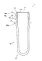
以下に、図面を参照しつつ、本発明の実施形態の詳細を説明する。まず、本実施形態に係るPET(PolyEthylene Terephthalate:ポリエチレンテレフタレート)ボトル成形用のプリフォーム1(予備成形体)の構成を詳細に説明する。図1は本実施形態に係るプリフォーム1の一例が示された断面図である。プリフォーム1は、有底筒状であって、口部10、胴部16、及び底部17が軸方向に順次設けられる。プリフォーム1が延伸されることによってボトル状に成形される。この際公知のブロー成形技術を用いるのが好適である。図1には、口部10から底部17までが軸方向と平行にプリフォーム1の中心で切断された面が示されている。
Hereinafter, the details of the embodiments of the present invention will be described with reference to the drawings. First, the configuration of a preform 1 (preformed body) for forming a PET (PolyEthylene Terephthalate: polyethylene terephthalate) bottle according to the present embodiment will be described in detail. FIG. 1 is a cross-sectional view showing an example of a
なお、以下では、説明の便宜上、図1の状態のプリフォーム1において底部17に対する口部10の方向を上とする。
In the following, for convenience of explanation, in the
口部10は、軸方向の上端に、円形に開放された開口部11を有している。開口部11は、環状の口天面15と円形の穴部11aを有している。そして、口部10は、その外周面に、おねじ12と、カブラ13と、サポートリング14とを有している。図示せぬ蓋を取り付けるためのおねじ12は口部10の外周面から、プリフォーム1の径方向の外側に向かってらせん状に突出している。カブラ13は、おねじ12の下方で、径方向外側に向かって周回状に突出している。サポートリング14は、カブラ13の下方で周回状に、カブラ13よりも径方向外側まで突出している。
The
一般的に、サポートリング14から軸方向の上側の箇所ではプリフォーム1からボトル状に成形される際にその形状が変化しない。一方で、サポートリング14よりも下側の最大10 mmの範囲でもボトル状に成形される際にほとんど延伸されない。したがってここでは、プリフォーム1からボトル状に成形される際にその形状がほとんど変化しない範囲を口部10と定義することとする。そして、口部10は、図1に例示されるように、サポートリング14よりも軸方向下側の箇所の内径、及び外径が軸方向の上下において略同寸の略真円筒形状であっても良い。
In general, at the upper portion in the axial direction from the
このように、口部10は、ブロー成形機による成形後もその形状が変化しない。ここで、プリフォーム1の口部10の内径や外径(ねじ谷径に相当)、ねじ山径といった各部の寸法に特に限定はない。しかしながら、飲料用ボトルで標準的に用いられている寸法とされることが、既存の蓋の汎用性や、飲料用ボトルの密封性を確保できる点で好ましい。このため、口部10は例えば、PCO1810規格や、PCO1881規格に対応した寸法とされると良い。
Thus, the shape of the
胴部16は、内径、及び外径が、軸方向の上下において略同寸の略真円筒形状に構成されている。ただし、胴部16には、プリフォーム1の作製の際に用いられる型からの取り出し、すなわち離型を容易にするための傾斜である抜き勾配が設けられていても良い。更に、胴部16の内径、及び外径が軸方向の上下でわずかに変化していても良い。更に、軸方向の上下において、胴部16の特に外径を略同寸に構成することもできる。
The
底部17は、外方に湾曲した略半球状に構成されている。底部17は、円錐形状であったり、角に丸みを持った円柱形状であったり、その他の形状であっても良い。
The
なお、胴部16の外径は、12 mm以上、30 mm以下であることが既存の装置を用いることができる点で好ましい。更に、サポートリング14の下面から底部17の下端までの長さが35 mm以上、105 mm以下であることが、既存の装置、特にブロー成形機を用いることができる点で好ましい。
In addition, it is preferable that the outer diameter of the trunk | drum 16 is 12 mm or more and 30 mm or less from the point which can use the existing apparatus. Furthermore, it is preferable that the length from the lower surface of the
プリフォーム1は、口部10が多層に構成されて、外層18aと内層19aとの間に中間層20aを有する。図1に例示されるプリフォーム1はおねじ12の上端から、口部10の下端まで中間層20aを有している。一方で、胴部16、底部17は、中間層20aを有さない構成となっている。このように口部のみに中間層を有する構成とすることで、口部に特別な機能を持たせることができる。胴部16や底部17は、図1に例示されるプリフォーム1においては、中間層20aを有していない。ただし、例えばバリア性に優れた中間層を胴部16や底部17に設けるなどの構成としてもよい。これによりさらなる多機能性を有するプリフォーム1とすることができる。
In the
プリフォーム1は、中間層20aと、外層18a、及び内層19aのそれぞれとの間に接着層や接着剤を有していない。このため、プリフォーム1は使用後に、再資源化が妨げられることがない。一方で、各層の間が固く接着されているわけではないので外力によって層間剥離が起きてしまう可能性がある。そこで、中間層20aが口部10の端まで延びずに構成されていることによって破壊の起点になりやすい各層の界面の端が口天面15にて露出せず層間剥離が生じにくくされている。ただし、製造を容易にするために、各層の界面の端を口天面15にて露出させて構成してもよい。
The
プリフォーム1は、図1に例示されるように、中間層20aが、口部10の上端から下端にかけて連続して設けられている。このとき、好ましくは中間層20aの端がおねじ12の上端である、いわゆるねじ始まり位置を上端として設けられているとよい。そして、中間層20aが、ねじ始まり位置を上端として設けられていることで、口述するように中間層が耐熱材料を用いていることから、ねじの噛み合わせがずれることがない。
In the
図1に例示されるように、中間層20aは、口部10の下端までの範囲に設けられている。耐熱材料を用いた中間層を口部10の範囲で設けることとすることで、後にブロー成形によりペットボトルに成形する際に、延伸しない部分にのみ中間層を有する構成となる。これにより、胴部16の延伸部分は図1に例示されるように、中間層を有さないこととすることができる。本開示における中間層が胴部16にはみ出して設けられた場合には、製造上、型崩れが起こりやすい。よって、胴部16に中間層20aを有さない構成は優れている。ただし、ここでいう中間層20aが口部10にのみ設けられていることは、別個の中間層が胴部16や底部17に別個の中間層を設けることを排除するものではない。
As illustrated in FIG. 1, the
中間層20aの厚みは、均一に設けられている。均一に設けられていることにより、熱が加わり基材層が変形する場合であっても、ゆがむことが少ない。ただし、口部10のサポートリング14の基材層中に、中間層20aが、口部10から径方向に突出して設けられていてもよい。このようにするほうが容易にプリフォーム1を製造することができる。口部10の構成としては、基材層に囲まれて、中間層がフランジのように、サポートリング14の基材層中に突出して設けられ、そのほかの部分の中間層20aの厚みは、均一であるとの構成を有していてもよい。
The thickness of the
中間層20aは、全体の重量から中間層20aの重量を除した値が、280ミリリットルペットボトル用のプリフォーム1においては、1.5重量パーセント〜3重量パーセントであることが好ましい。これにより、プリフォーム1をブロー成形などにより成形したペットボトル2のリサイクル性が向上する。ペットボトルのサイズによってこの比率は異なりうるものの、この比率は口部の重量に対しての割合としては、5〜10重量パーセントに相当する。2リットルペットボトル用においても、3重量パーセントであればリサイクル性としては、上記の280ミリリットルペットボトル用のプリフォーム1と、異なるところはない。
It is preferable that the value which remove | divided the weight of the intermediate |
中間層20aには、各種機能を発揮する材料を選択することができる。例えば、中間層20aには、紫外線等の光の遮断性や、水蒸気等のガスバリア性を付与する材料を用いることができる。ここでの中間層20aは、耐熱材料を用いることが好適である。ここで耐熱材料とは、ポリアリレートやナイロンなどの耐熱性を有する物質や、ポリアリレートを用いてもよい。熱可塑性ポリエステル樹脂で耐熱性に優れたものも、本発明の耐熱材料において用いることができる。
For the
例示されたプリフォーム1の基材層20の外層18a、及び内層19aの材料としては、高密度ポリエチレン、中密度ポリエチレン、低密度ポリエチレン、線状低密度ポリエチレン、ポリプロピレン等のポリオレフィンや、エチレン−ビニルアルコール共重合体、植物等を原料としたポリ乳酸等のブロー成形が可能な種々の熱可塑性樹脂を用いることができる。しかしながら、外層18a、及び内層19aは、ポリブチレンテレフタレート、ポリエチレンナフタレート、ポリカーボネート、ポリアリレート等のポリエステル、特に、ポリエチレンテレフタレートが主成分のPET層とされることが好ましい。なお、上述された樹脂には、成形品の品質を損なわない範囲で種々の添加剤、例えば着色剤、紫外線吸収剤、離型剤、滑剤、核剤、酸化防止剤、帯電防止剤を配合することができる。
As materials for the
プリフォーム1の外層18a、及び内層19aを構成するエチレンテレフタレート系熱可塑性樹脂としては、エステル反復部分の大部分、一般に70 mol%以上をエチレンテレフタレート単位が占めるものであり、ガラス転移点(Tg)が50 ℃以上、90 ℃以下であり、融点(Tm)が200 ℃以上、275 ℃以下の範囲にあるものが好適である。エチレンテレフタレート系熱可塑性ポリエステルとして、ポリエチレンテレフタレートが耐圧性等の点で特に優れているものの、エチレンテレフタレート単位以外に、イソフタル酸や、ナフタレンジカルボン酸等の二塩基酸と、プロピレングリコール等のジオールからなるエステル単位を少量含む共重合ポリエステルも使用することができる。
The ethylene terephthalate-based thermoplastic resin constituting the
ポリエチレンテレフタレートは熱可塑性の合成樹脂の中では生産量が最も多い。そして、ポリエチレンテレフタレート樹脂は、耐熱性、耐寒性や、耐薬品性、耐摩耗性に優れる等の種々の特性を有する。更に、ポリエチレンテレフタレート樹脂はその原料に占める石油の割合が他のプラスチックと比べて低く、リサイクルも可能である。このように、ポリエチレンテレフタレートを主成分とする構成によれば、生産量の多い材料を用いることができ、その優れた種々の特性を活用することができる。 Among the thermoplastic synthetic resins, polyethylene terephthalate produces the largest amount. The polyethylene terephthalate resin has various properties such as excellent heat resistance, cold resistance, chemical resistance, and abrasion resistance. Furthermore, the proportion of petroleum in the raw material of polyethylene terephthalate resin is lower than that of other plastics, and recycling is also possible. Thus, according to the structure which has a polyethylene terephthalate as a main component, material with a large amount of production can be used, and the various excellent characteristics can be utilized.
ポリエチレンテレフタレートは、エチレングリコール(エタン−1,2−ジオール)と、精製テレフタル酸との縮合重合によって得られる。ポリエチレンテレフタレートの重合触媒として、ゲルマニウム化合物、チタン化合物、及びアルミニウム化合物の少なくとも一つが用いられることが好ましい。これらの触媒が用いられることによって、アンチモン化合物が用いられるよりも、高い透明性を有し、耐熱性に優れた容器を形成することができる。 Polyethylene terephthalate is obtained by condensation polymerization of ethylene glycol (ethane-1,2-diol) and purified terephthalic acid. It is preferable to use at least one of a germanium compound, a titanium compound, and an aluminum compound as a polymerization catalyst for polyethylene terephthalate. By using these catalysts, it is possible to form a container having higher transparency and superior heat resistance than the case of using an antimony compound.
プリフォーム1の全体に対する中間層20aの量が多すぎるとプリフォーム1の使用後に再資源化が妨げられてしまう。一方で、プリフォーム1の全体に対する中間層20aの量は少なすぎると、射出成形性が低下してしまう。より詳細には、プリフォーム1の成形の際に中間層20aが充填されにくくなり、これを無理やり押し込むと変質や偏肉が生じて好ましくない。したがって、プリフォーム1の全体に占める中間層20aの割合は少なくとも0.5重量パーセント以上必要である。さらに言えば、1.5重量パーセント〜3重量パーセントであることが好ましい。
If the amount of the
なお、中間層20aは単層に限らず多層で構成されていても良く、例えば耐熱材料を用いた耐熱層の他に、酸素バリア層を複数含んで構成されていても良い。例えば、プリフォーム1は、5層構造(PET層(外層18a)/酸素バリア層/耐熱層/酸素バリア層/PET層(内層19a))とされていても良い。中間層20aの層数が更に増やされていても良く、プリフォーム1を最大で、7層構造とすることもできる。中間層20aが多層で構成されることによって、中間層20aの機能をより高めたり、中間層20aに複数の機能を持たせたりすることができる。
The
本実施形態に係るプリフォーム1の製造方法では、口部10の基材層中において均一な厚みの中間層20aが成形される。ただし、中間層20aが口部10のサポートリング14内に突出するように成形されてもよい。このように製造されるプリフォーム1によれば、中間層20aの延伸後において、延伸しない部分である口部10のみに中間層の範囲がとどまっていることから、中間層の延伸による形崩れ等を防止することができる。そして、口部のみに中間層を設けることで、口部10の耐熱性を確保しつつ、中間層20aの成形材料の量を減少することができるため再資源化が容易となる。
In the method of manufacturing the
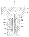
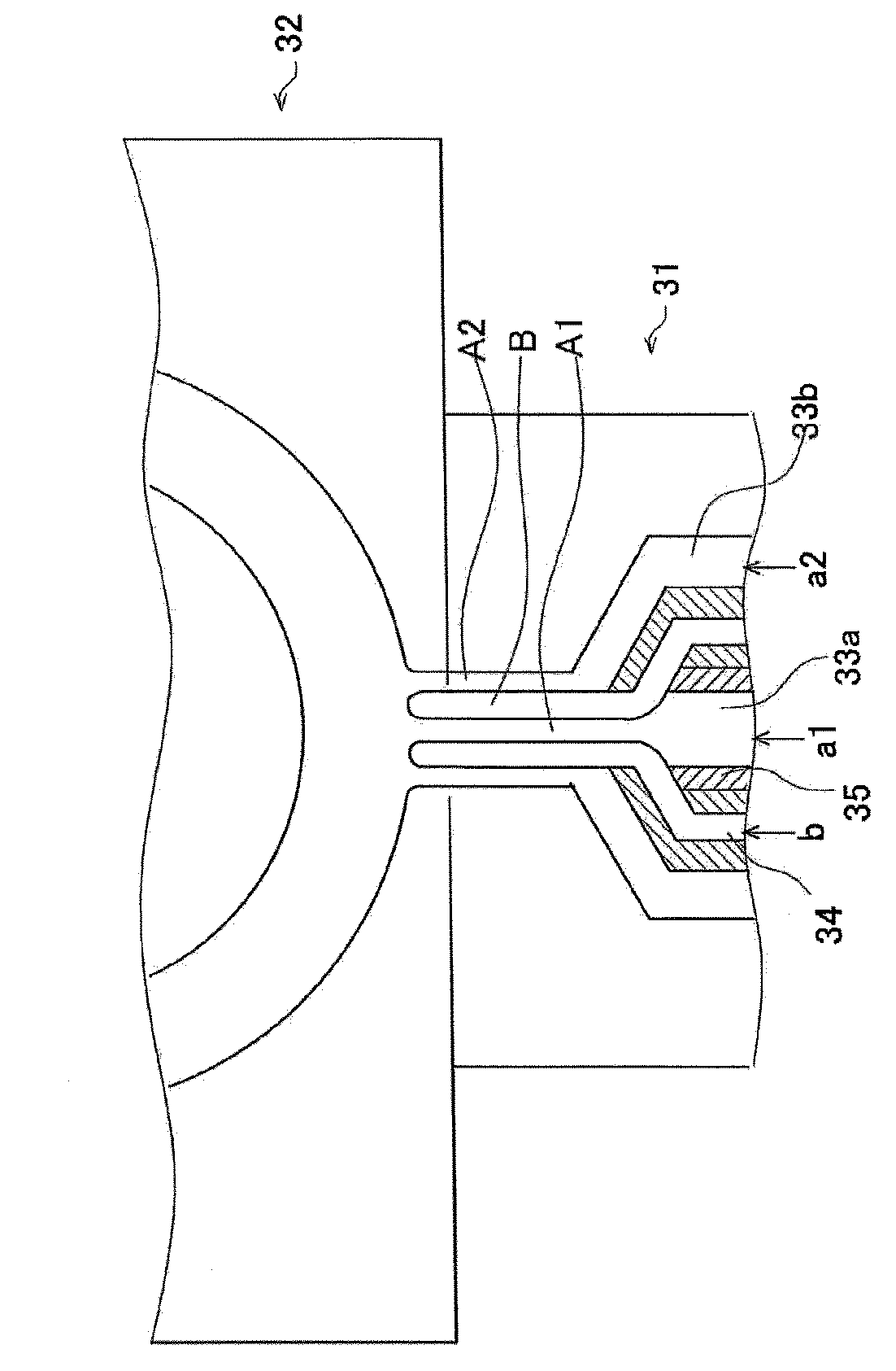
そこで、次に、プリフォーム1の製造方法の一例を詳細に説明する。図2は、プリフォーム1の製造装置の一例として、射出成形装置30のホットランナーノズル31の概略が示された断面図である。射出成形装置30は、内部にスクリュを備える図示せぬ加熱シリンダと、ホットランナーノズル31と、金型32とを備えている。射出成形装置30は、成形材料が、加熱シリンダで、例えば270 ℃〜300 ℃に加熱されることによって溶融可塑化され、スクリュによって、ホットランナーノズル31を介して金型32に送り出されるように構成されている。
Then, next, an example of a manufacturing method of
ホットランナーノズル31は軸方向に長い構成である。ホットランナーノズル31は、直線状流路33aと、第1の円筒状流路33bと、第2の円筒状流路34と、開閉弁の一例であるチェック弁35とを有している。各流路は、略軸方向に延びている。ホットランナーノズル31は、第1の注入口36と、第2の注入口37と、射出口38とを更に有している。
The
射出口38は、ホットランナーノズル31の一端の中心に形成されている。そして、射出口38は金型32と連通している。一方で、第1の注入口36、及び第2の注入口37はホットランナーノズル31の他端寄りの側面にそれぞれ形成されている。そして、第1の注入口36、及び第2の注入口37のそれぞれは別々の加熱シリンダと接続されている。すなわち、ホットランナーノズル31は、第1の注入口36、及び第2の注入口37からそれぞれ第1の成形材料、及び第2の成形材料を注入することができるように構成されている。成形材料は、第1の注入口36、及び第2の注入口37から射出口38に向かって流れる。このため、図1において下側に示されているホットランナーノズル31の他端が成形材料の上流側となる。
The
直線状流路33aは、第1の注入口36から径方向に延びる流路と連通し、ホットランナーノズル31の中央部を射出口38まで直線状に延びている。第1の円筒状流路33bは、直線状流路33aから分岐した後に、直線状流路33aの径方向外方を通り、射出口38に近い第1の合流点39aで直線状流路33aと合流している。第2の円筒状流路34は、第2の注入口37から径方向に延びる流路と連通し、直線状流路33aと、第1の円筒状流路33bとの間に延びて第1の合流点39aよりも上流の第2の合流点39bで直線状流路33aと合流している。
The
ホットランナーノズル31は、第2の合流点39bに、第2の円筒状流路34を閉鎖するチェック弁35を有している。チェック弁35は、第2の合流点39bにおける直線状流路33aを通過する第1の成形材料と第2の円筒状流路34を通過する第2の成形材料との射出圧の差に応じて軸方向に動くように構成されている。そして、チェック弁35は、第2の成形材料の射出圧が高い場合には第2の円筒状流路34を開放するように構成されている。このような作用を果たすのであればチェック弁35は、他の構成であっても構わない。
The
複数に分割されて構成される金型32は、プリフォーム1に対応する形状の空隙であるキャビティ32a、及びプリフォーム1の底部17に対応する位置にゲート32bを有している。キャビティ32aは、ゲート32bを介して、ホットランナーノズル31の射出口38に連通している。金型32には、金型32を加熱する図示せぬヒータと、金型32を冷却する図示せぬ冷却機とが設けられている。金型32は、ヒータによって加熱されたキャビティ32aに溶融した成形材料が注入、及び加圧された後に冷却機によって冷却され、プリフォーム1が成形されるように構成されている。
The
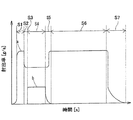
図3は、共射出される各成形材料の射出率と時間との関係が模式的に示されたグラフである。射出率は、単位時間[s]当たりに射出される各成形材料の質量[g]で示されている。図3において、第1の成形材料は実線で示され、第2の成形材料は破線で示されている。そして、ここでは、第1の成形材料には、ポリエチレンテレフタレート(以下では、PET樹脂aと称す)が注入され、第2の成形材料には、ポリアリレート(以下では、耐熱性樹脂bと称す)が注入される例が示されている。そして、例えば、プリフォーム1の製造方法は、図3に示されるように、第1の成形材料を射出する工程(ステップS1)と、第1の成形材料より高い射出率で第2の成形材料を射出する工程(ステップS4〜ステップS5)と、第2成形の材料より高い射出率で第1の成形材料を射出する工程(ステップS5)とを有し、第1の成形材料より高い射出率で第2の材料を射出する工程(ステップS4〜ステップS5)において、第2の成形材料の射出率を漸増する工程(ステップS4)を含む。そして、この方法によれば、製造されたプリフォーム1の中間層20aの延伸後においてもその機能を確保しつつ、中間層20aの成形材料の量を減少することができる。
この図の射出タイミングに従い射出成形を行うことで、口天面に中間層20aが露出していない、本発明のプリフォームの一形態を成形することができる。
FIG. 3 is a graph schematically showing the relationship between injection rate and time of each molding material to be co-injected. The injection rate is indicated by the mass [g] of each molding material injected per unit time [s]. In FIG. 3, the first molding material is shown as a solid line and the second molding material is shown as a broken line. Here, polyethylene terephthalate (hereinafter referred to as PET resin a) is injected into the first molding material, and polyarylate (hereinafter referred to as heat resistant resin b) is injected into the second molding material. An example is shown where is injected. Then, for example, as shown in FIG. 3, in the method of manufacturing the
By performing injection molding according to the injection timing of this figure, it is possible to form one form of the preform of the present invention in which the
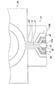
まず、PET樹脂aが射出される(ステップS1)。図4は、ホットランナーノズル31からキャビティ32aへと各成形材料が流動する状態(ステップS1)の概略が示された断面図である。PET樹脂aは、第1の注入口36(図2参照)から、直線状流路33a(PET樹脂a1)、及び第1の円筒状流路33b(PET樹脂a2)のいずれかを経由して第1の合流点39aで合流し、その後、射出口38、ゲート32bの順に流動してキャビティ32aに充填される。図4に例示されるように、直線状流路33a(PET樹脂a1)、及び第1の円筒状流路33b(PET樹脂a2)のそれぞれを経由したPET樹脂aの流れがPET樹脂層A1、及びPET樹脂層A2を構成し、PET樹脂層Aとしてキャビティ32aに充填されている。
First, PET resin a is injected (step S1). FIG. 4 is a cross-sectional view schematically showing the molding materials flowing from the
この段階では、耐熱性樹脂bは射出されておらず、PET樹脂a1の射出圧を受けるチェック弁35によって第2の円筒状流路34は閉鎖されている。
At this stage, the heat-resistant resin b is not injected, and the second
次に、PET樹脂a1が、予め定められた射出率まで下げられて射出される(ステップS2)。この下げられた射出率は、次の段階において射出される耐熱性樹脂bの射出率との兼ね合いで決まる。ここで、ステップS1においても、この予め下げられた射出率でPET樹脂aが射出された場合に口部10の寸法不良やヒケ等の賦形不良が生じないのであれば、ステップS2が省略されても良い。
Next, the PET resin a1 is lowered to a predetermined injection rate and injected (step S2). The lowered injection rate is determined in balance with the injection rate of the heat resistant resin b injected in the next stage. Here, also in step S1, if PET resin a is injected at this previously lowered injection rate, if there is no dimensional defect in the
次に、PET樹脂a1より高い射出率で耐熱性樹脂bが射出される(ステップS3)。図5は、ホットランナーノズル31からキャビティ32aへと各成形材料が流動する状態(ステップS3)の概略が示された断面図である。耐熱性樹脂bが射出される圧力によってチェック弁35が動き、第2の円筒状流路34は開放される。そして、図5に例示されるように、直線状流路33aを経由したPET樹脂層A1と、第1の円筒状流路33bを経由したPET樹脂層A2との間に耐熱性樹脂層Bが形成されている。耐熱性樹脂層Bは、成形型に接触せずに流動して温度の低下が少なく粘度が高まらないのでPET樹脂層A1、及びA2よりも高い速度で流動している。
Next, the heat resistant resin b is injected at an injection rate higher than that of the PET resin a1 (step S3). FIG. 5 is a cross-sectional view schematically showing the molding materials flowing from the
次に、耐熱性樹脂bの射出率が同程度に保たれながら射出される(ステップS4)。図6は、ホットランナーノズル31からキャビティ32aへと各成形材料が流動する状態(ステップS4)の概略が示された断面図である。
Next, the heat-resistant resin b is injected while maintaining the injection ratio of the same degree (step S4). FIG. 6 is a cross-sectional view schematically showing the molding materials flowing from the
次に、耐熱性樹脂bの射出率が漸減して零となるまで射出されるとともにPET樹脂aの射出率が漸増するように射出される(ステップS5)。耐熱性樹脂bの射出率が漸減することによって耐熱性樹脂層Bが徐々に薄くなるように射出された後に途切れる。そして、耐熱性樹脂bの射出率が零となることによってチェック弁35が動き、第2の円筒状流路34が閉鎖される。
Next, injection is performed until the injection ratio of the heat resistant resin b gradually decreases and becomes zero, and injection is performed so that the injection ratio of the PET resin a gradually increases (step S5). After the injection ratio of the heat resistant resin b gradually decreases, the heat resistant resin layer B is injected so as to be gradually thinner and then it is interrupted. Then, when the injection rate of the heat resistant resin b becomes zero, the
次に、PET樹脂aが予め定められた射出率に維持されて射出される(ステップS6)。図7は、ホットランナーノズル31からキャビティ32aへと各成形材料が流動する状態(ステップS6)の概略が示された断面図である。図7に例示されるように、耐熱樹脂層BがPET樹脂層Aによって押し込まれていく。
Next, the PET resin a is maintained at a predetermined injection rate and injected (step S6). FIG. 7 is a cross-sectional view schematically showing the molding material flowing from the
最後に、キャビティ32aの内部が充満されるまでPET樹脂aが射出される(ステップS8)。PET樹脂aの射出率が漸減し、そして、キャビティ32aの内部が充満されるとPET樹脂aの射出率が零となり、その後は、PET樹脂aが逆流しないように保圧が行われる。そして、キャビティ32aの内部で成形材料が冷却された後に、金型32が開き、成形されたプリフォーム1が取り出される。
Finally, the PET resin a is injected until the inside of the
なお、各成形材料を射出する圧力や、射出率はそれぞれの粘度の差等に応じて適宜設計される。 The pressure at which each molding material is injected and the injection ratio are appropriately designed according to the difference in viscosity and the like.
以上のように、本実施形態に係るプリフォーム1の製造方法は、中間層20aを均一に成形する手順を含んで構成される。
As described above, the method for manufacturing the
例えば、プリフォーム1の製造装置は、ホットランナーノズル31が、第1の注入口36から延びる直線状流路33aと、直線状流路33aから分岐した後に第1の合流点39aで合流する第1の円筒状流路33bと、第2の注入口37から直線状流路33aと第1の円筒状流路33bとの間に延びて第1の合流点39aよりも上流の第2の合流点39bで直線状流路33aと合流する第2の円筒状流路34と、第2の合流点39bにおける直線状流路33aを通過する第1の材料と第2の円筒状流路34を通過する第2の材料との射出圧の差に応じて第2の円筒状流路34を開放するチェック弁35とを有し、プリフォーム1に対応するキャビティ32a、及びプリフォーム1の底部17に対応する位置にゲート32bを有する金型32と、ゲート32bに連通するホットランナーノズル31とを備える。
For example, in the apparatus for
なお、製造方法は、他の方法であっても構わない。例えば、PET樹脂a、耐熱性樹脂b、PET樹脂aの順に可塑化して押し出して耐熱性樹脂bがU字状に内包された溶融樹脂塊(ビレット)を生成し、これを圧縮成形することでプリフォーム1が製造される方法であっても良い。
The manufacturing method may be another method. For example, by plasticizing and extruding the PET resin a, the heat resistant resin b, and the PET resin a in this order, a molten resin block (billet) in which the heat resistant resin b is enclosed in a U shape is generated and compression molded. It may be a method by which the
成形されたプリフォーム1は、箱積み、いわゆるパレタイジングされて倉庫等でいったん保管されても良く、そのまま、引き続き、次の工程へと進められても良い。すなわち、プリフォーム1の成形と、ブロー成形とが別の場所や装置で行われる、いわゆるコールドパリソン方式(2ステージ方式)であっても良く、プリフォーム1の成形と、ブロー成形とが同じの場所や装置で行われる、いわゆるホットパリソン方式(1ステージ方式)であっても良い。更に、プリフォーム1の成形から内容物の充填等に至るまでの製造工程がインラインで連続的なものであっても良い。
The formed
次に、本実施形態に係るプリフォーム1からボトル状に成形する方法の一例を詳細に説明する。プリフォーム1がボトル状に成形されるにあたってまず、プリフォーム1の加熱が行われる。図8は、プリフォーム1の加熱装置40の一例が示された断面図である。なお、図8は、プリフォーム1の搬送方向に対して垂直方向の断面を示す。
Next, an example of a method of forming the
加熱装置40は、搬送装置41と、ヒータ42とを備えている。搬送装置41は、プリフォーム1を周方向に均等に加熱するために、プリフォーム1の軸を中心に回転させながら搬送するように構成されている。ヒータ42は、複数の例えばハロゲンランプによって構成され、ブロー成形に適した温度例えば80 ℃〜140 ℃にプリフォーム1を加熱するように構成されている。更に、加熱装置40は、ヒータ42からの熱をプリフォーム1に反射させるための反射板43や、ヒータ42からの熱を加熱装置40の外方へ逃がさないようにするための遮蔽部材44等を備えていても良い。なお、図8の加熱装置40では、プリフォーム1は口部10が下側を向いた状態で搬送、及び加熱されている。
The
加熱されたプリフォーム1は次に、ブロー成形機によって、プラスチックボトル例えばPETボトル2に成形される。図9は、プリフォーム1と、ブロー成形後のPETボトル2とが模式的に示された断面図である。ブロー成形機の一例としての二軸延伸ブロー成形装置50は、金型51と、延伸ロッド52と、図示せぬ高圧エア供給装置と、これらを制御する図示せぬ制御装置とを備えている。なお、図9には、下向きのブロー成形方法が例示されているものの、材料が重力の影響を受けにくい上向きのブロー成形方法が用いられても良い。
The
ここで、PETボトル2は、上部30と、胴部70と、下部80とを有する。ブロー成形の前後においておおよそ、プリフォーム1の口部10がPETボトル2の上部30に対応し、プリフォーム1の底部17がPETボトル2の下部80に対応する。
Here, the
金型51は、形成されるPETボトル2に対応した形状を有しており、例えば、胴部70に対応して半割りで構成される胴金型51aと、下部80に対応した底金型51bとを有する。金型51の表面の温度は、PETボトル2の用途、特に耐熱性に応じて例えば30 ℃〜130 ℃に制御されるように構成されている。
The
延伸ロッド52は金型51内を伸縮自在に構成される。そして、延伸ロッド52は、金型51に口部10の取り付けられたプリフォーム1の首部15、及び胴部16を縦(軸)方向に延伸するように構成される。高圧エア供給装置からは、温度調節された高圧エアhが吹き出されるように構成される。高圧エアhは、金型51に取り付けられたプリフォーム1の内部に供給されれば良く、延伸ロッド52から吹き出されても良く、延伸ロッド52とは別の部材から吹き出されても構わない。高圧エアhは、プリフォーム1の胴部16を横(径)方向に延伸するとともに、延伸の後に胴部16の表面温度を下げるように構成される。
The
加熱されたプリフォーム1は、二軸延伸ブロー成形装置50の金型51に装着される。その後には、金型51に装着されたプリフォーム1の胴部16が延伸ロッド52によって縦方向に延伸される。この際のプリフォーム1からPETボトル2への縦延伸倍率は1.8倍以上、4.0倍以下であることが好ましい。
The
ここで、縦延伸倍率とは、プリフォーム1のサポートリング14の下面から底部17の下端までの長さに対するPETボトル2のサポートリング14の下面から下部80の下端までの長さの比である。非晶部と、結晶部との集合体であるアモルファス構造を有するプリフォーム1の分子は延伸によって配向結晶化がおこり、その結果として、PETボトル2の強度や、剛性、耐熱性等が上がる。縦延伸倍率が1.8未満の場合にはPETボトル2(プリフォーム1)の分子の配向性が上がらず、一方で、縦延伸倍率が4.1以上の場合にはPETボトル2が成形しにくくなる。
Here, the longitudinal stretching ratio is the ratio of the length from the lower surface of the
更に、縦方向に延伸されたプリフォーム1の胴中部16が高圧エアhによって横方向に、金型51に当たるまで延伸される。この際のプリフォーム1からPETボトル2への横延伸倍率は1.5倍以上、6.0倍以下であることが好ましい。
Further, the
ここで、横延伸倍率とは、プリフォーム1の胴中部16における胴径に対するPETボトル2の胴部70における胴径の比である。なお、胴部70の対向するそれぞれの壁面における肉厚の中心間の距離が胴部70の胴径とされる。プリフォーム1の分子は横方向の延伸によっても同様に配向結晶化がおこり、その結果として、PETボトル2の強度や、剛性、耐熱性等が上がる。横延伸倍率が1.5未満の場合にはPETボトル2(プリフォーム1)の分子の配向性が上がらず、一方で、横延伸倍率が6.1以上の場合にはPETボトル2が成形しにくくなる。
Here, the lateral stretching ratio is the ratio of the barrel diameter of the
このように、二軸延伸ブロー成形装置50による成形が、縦方向の延伸倍率が1.8倍以上、4.0倍以下、横方向の延伸倍率が1.5倍以上、6.0倍以下の二軸延伸ブロー成形である構成によれば、プリフォーム1からより良好なブロー成形性で軽量化されたPETボトル2を成形することができる。
Thus, in the molding by the biaxial stretch
以上のように、本実施形態に係るPETボトル2はプリフォーム1が、二軸延伸ブロー成形装置50でボトル状に成形される。そして、二軸延伸ブロー成形装置50が用いられることによって効果的に、本実施形態に係るプリフォーム1から良好なブロー成形性で軽量化されたPETボトル2を成形することができる。
As described above, in the
なお、本実施形態においては、成形されるPETボトル2の用途が限定されない。したがって、PETボトル2は、耐圧性や酸素バリア性等を有するように成形されても良い。
In the present embodiment, the application of the molded
次に、本実施形態に係るプリフォーム1から形成されるPETボトル2の構成を詳細に説明する。図10は、本実施形態に係るプリフォーム1から形成されたPETボトル2が示された正面図である。図10に例示されたPETボトル2は軸方向とは垂直方向の断面視が略円形の丸ボトルである。上述されたように、PETボトル2は、上部30と、胴部70と、下部80とを有する。そして、上述されたように、PETボトル2の上部30の構成はプリフォーム1の口部10の構成と同様である。
Next, the configuration of the
上部30は、中身の充填口、及び注出口となり、上部30に、図示せぬ蓋が取り付けられることによってPETボトル2が密閉される。
The
胴部70は、上部と隣接する部分が上方から下方に向かって拡径する略円錐台の形状を有している。胴部において、該略円錐台の形状の部分と底部の間の部分は、円筒の形状を有している。胴部70は、圧力吸収パネルや、横溝、縦溝を有していても良い。
The
図12に示すように、下部80はその上側が、胴部70の下側に連なる。図10に例示された下部80はいわゆるペタロイド形状である。下部80は、凹部81や、脚部82、谷部83等を有している。下部80の径方向中央に位置する凹部81は、PETボトル2の内側(軸方向上側)に向かって突出するように構成されている。脚部82は、凹部81から径方向外側に放射状に、軸方向の下側に向かって延びている。脚部82は、PETボトル2の接地面となる。隣り合う脚部82の間には谷部83が形成されている。谷部83は、凹部81から、径方向外側、かつ軸方向の上側に向かって延びている。下部80の構成は、図10の例示に限らず、内容物に対応した形状、例えば放射状にリブが設けられた形状であっても良い。
As shown in FIG. 12, the upper portion of the
図11は、PETボトル2の断面図である。更に、図11では、上部30の領域Aが拡大されて示されている。PETボトル2は、上部30が多層に構成されて、外層18と内層19との間に中間層20を有する。PETボトル2は、プリフォーム1と同様に、中間層20が、上部10の基材層中に構成されていることが好ましい。このとき、中間層20の上端が、ねじ始まり位置と同じ位置もしくはその上であると、キャップとおねじの噛み合わせが悪くなることがなくなり、良い。口天面より1mm下から中間層が始まり、サポートリング下3mmまで中間層が存する構成では、ねじ始まり位置より上から中間層が形成されることになり、耐熱性樹脂を用いた中間層の場合、口部の耐熱性が増し、好ましいこととなる。ただし、成型時の延伸しやすさを考慮すると、口天面より3mm下から始まり、サポートリングから下に3mmまでの中間層とし、サポートリング下は短い中間層としたほうが、成形性は向上するためより好ましい。
FIG. 11 is a cross-sectional view of the
口部に中間層を設けることにより、液漏れを防止したペットボトルを成形できるプリフォームとすることができ、好適である。 By providing the middle layer in the mouth, it is possible to obtain a preform capable of forming a plastic bottle in which liquid leakage is prevented, which is preferable.
なお、中間層20の種類や、材料、量、層構成等については上述されたプリフォーム1と同様である。
The type, material, amount, layer configuration and the like of the
PETボトル2の特にサポートリング14よりも下の形状は、図10等の例示に限らず、プリフォーム1がブロー成形されることによって形成されるものであればどのような形状であっても良い。例えば、本実施形態においては、図10に示された丸ボトルを好適に形成することができる。しかしながら、本実施形態において形成されるプラスチックボトルは丸ボトルには限定されず、角ボトルであっても良い。更に、胴部70の幅が下方に向けて拡開する形状であっても良い。そして、胴部70に形成される圧力吸収パネルや、横溝、縦溝の形状についても自由に設計することができる。
The shape of the
本実施形態に係るPETボトル2にはサイズによる限定はなく、種々のサイズに対して適用することができる。例えば、PETボトル2の容積が100 ml以上、1000 ml以下であっても良く、特に、容積が200 ml以上、700 ml以下であるPETボトル2に対して好適である。PETボトル2の全高は120 mm以上、260 mm以下であっても良く、胴部70の胴径は40 mm以上、75 mm以下であっても良い。
The
更に、本実施形態に係るPETボトル2は軽量化ボトルを対象として好適に用いることができる。PETボトル2の質量は例えば、200 mlの内容積に対しては12 g以上、14 g未満、550 mlの内容積に対しては13 g以上、15 g未満であると良い。そして、特に、軽量性を有し、中間層20の機能を確保しながらPETボトル2の強度を保つ観点から、PETボトル2の内容積に対する質量の比の値が0.0125 g/ml以上、0.0700 g/ml以下であることが好ましい。
Furthermore, the
上述された材料が射出成形されたプリフォーム1がブロー成形されることによってプラスチックボトルを作製することができる。そして、材料として、ポリエチレンテレフタレートが用いられることによって、本実施形態に係るプラスチックボトルの一例としてのPETボトル2が作製される。そして、PETボトル2と、充填される液体とによって充填体が構成される。充填体は、PETボトル2の上部30から飲料や調味料等の液体が充填され、上部30に装着される図示せぬ蓋によって密封されることによって製造される。
A plastic bottle can be produced by blow molding a
なお、PETボトル2への内容物の充填方法についても限定されない。したがって、PETボトル2は、ホット充填に用いられても、アセプティック充填に用いられても良い。
In addition, it is not limited about the filling method of the content to
以上のように、PETボトル2は、上部30、胴部70、及び下部80を軸方向に順次有し、口部30が多層に構成されて、外層18と内層19との間に中間層20を有する。このような構成によれば、中間層20の機能を確保しつつ、中間層20の成形材料の量を減少することができる。もちろん成形材料を削減した分、別の中間層を別の部位に設けることもできる。
As described above, the
以下に、実施例を示して、本開示を更に詳細、かつ具体的に説明する。しかしながら、本開示は、以下の実施例に限定されるものではない。 Hereinafter, the present disclosure will be described in more detail and specifically by showing examples. However, the present disclosure is not limited to the following examples.
<材料、及び製造方法>
[実施例1]
外層18、及び内層19にはポリエチレンテレフタレート(PET樹脂a)が用いられ、中間層20には、ポリアレート(耐熱性樹脂b)が用いられ、全体で22 gのプリフォーム1が図3等本明細書に示される方法によって作製された。プリフォーム1の全体に占める耐熱性樹脂bの割合は3重量パーセントとされた。プリフォームの重量は21.8gであった。
<Materials and manufacturing method>
Example 1
Polyethylene terephthalate (PET resin a) is used for the
そして、プリフォーム1から、図10等に示される満注容量が295 mlのPETボトル2がブロー成形によって作製された。ブロー成形機にはLB01が用いられた。PETボトル2には、280mlの水が充填された後に蓋が装着され、充填体が作製された。
Then, from the
実施例1に係るプリフォーム1の中間層20は、例えば均一の厚みである、口部の基材層に囲まれている等といった本実施形態に係る特徴を有していた。中間層は、口天面から約1mmの位置から、サポートリングの下3mmの範囲に連続して設けられていた。
The
[比較例1]
比較例1では、耐熱性樹脂bを使用せず、PET樹脂aのみを用いて単層のプリフォームが作製された。プリフォームの重量は21.8gであった。そして、図10等に示される満注容量が295 mlのPETボトル2がブロー成形によって作製された。ブロー成形機にはLB01が用いられた。PETボトル2には、280mlの水が充填された後に蓋が装着され、充填体が作製された。
Comparative Example 1
In Comparative Example 1, a single-layer preform was produced using only the PET resin a without using the heat-resistant resin b. The weight of the preform was 21.8 g. Then, a
<評価方法>
(耐熱層の材料の使用量)
実施例1、並びに比較例1の各PETボトルに使用された耐熱層の材料の質量によって使用量の削減が達成できているか否かが判定された。使用量の削減の判定には、各PETボトル(各プリフォーム)の全体に占める耐熱性樹脂bの割り合いが20 wt%より大か、以下か、及び5 wt%より大か、以下かが閾値として設定された。表1には、各PETボトルにおける耐熱層の材料使用量の削減率についての評価の結果が示され、◎:削減率が極めて高い、○:削減率が高い、×:削減率が低い、で表記されている。
<Evaluation method>
(Use of material of heat-resistant layer)
It was judged by the mass of the material of the heat-resistant layer used for each PET bottle of Example 1 and Comparative Example 1 whether or not the reduction of the usage could be achieved. In the determination of the reduction in the amount used, the proportion of the heat resistant resin b in the whole of each PET bottle (each preform) is more than 20 wt%, less than, and more than 5 wt%, or less It was set as a threshold. Table 1 shows the evaluation results of the reduction rate of the material usage of the heat-resistant layer in each PET bottle, ◎: extremely high reduction rate, :: high reduction rate, x: low reduction rate, It is written.
(耐熱性)
実施例1並びに比較例1の各ペットボトルで、耐熱性が十分に達成できているか否かが判定された。耐熱性の判定には、各ペットボトルに常温水を充填し、キャップをしめ、70度で保温庫に1週間保存した。その後、口栓部の寸法を測定し、その膨張変化量を比較した。それをまとめたものが表2ある。
(Heat-resistant)
It was determined whether heat resistance could be sufficiently achieved in each of the plastic bottles of Example 1 and Comparative Example 1. For determination of heat resistance, each plastic bottle was filled with normal temperature water, the cap was closed, and stored at 70 ° C. for 1 week in a heat preservation cabinet. Thereafter, the dimensions of the plug portion were measured, and the amount of expansion change was compared. Table 2 summarizes it.
比較例1でネジ山径の膨張変化量を測定したところ、0.35mmであり、ネジ谷径は0.14mm、サポートリング径は0.76mm、サポートリング下径は1.52mmであった。これに対し、実施例1では、ネジ山径で0.09mm、ネジ谷径で0.05mm、サポートリング径で0.22mm、サポートリング下径で0.35mmと、いずれも低い数値であった。そのため、耐熱性としては、比較例1よりも実施例1のほうが優れているものとされた。 The expansion variation of the thread diameter in Comparative Example 1 was measured to be 0.35 mm, the thread valley diameter was 0.14 mm, the support ring diameter was 0.76 mm, and the support ring lower diameter was 1.52 mm. On the other hand, in Example 1, the thread diameter was 0.09 mm, the thread valley diameter was 0.05 mm, the support ring diameter was 0.22 mm, and the support ring lower diameter was 0.35 mm. Therefore, Example 1 was considered to be superior to Comparative Example 1 as heat resistance.
(総合評価)
上述された耐熱層の材料の使用量、耐熱性に基づいて、実施例1〜3並びに比較例1〜2の各PETボトル(各充填体)の総合評価がなされた。表1には、総合評価の結果が示されている。総合評価は、◎:極めて良好、○:良好、×:適性なし、で表記されている。
(Comprehensive evaluation)
Based on the usage of the material of the heat-resistant layer mentioned above, and heat resistance, comprehensive evaluation of each PET bottle (each filling body) of Examples 1-3 and Comparative Examples 1-2 was made. Table 1 shows the results of the comprehensive evaluation. The overall evaluation is indicated by ◎: very good, :: good, x: no suitability.
比較例1は耐熱性が不足していた。実施例1は耐熱性も十分であり、結果は良好であった。よって、以上の実施例の結果から、本実施形態に係るプリフォーム1、及びPETボトル2(充填体)では、口部10及び上部30に中間層が設けられることによって、耐熱性を備え、かつ耐熱層の材料の使用量が削減されることが示された。したがって、本実施形態では、中間層20の機能が確保されていながら、中間層20の成形材料の量が減少されたPETボトル2、プリフォーム1、及びプリフォーム1の製造方法を提供することができることが示された。
The heat resistance of Comparative Example 1 was insufficient. The heat resistance of Example 1 was also sufficient, and the results were good. Therefore, according to the results of the above-described examples, in the
本開示は、中身として液体が充填される種々のプラスチックボトルに好適に利用することができる。しかしながら、本開示は、上述された実施形態や実施例に限定されるものではない。本開示のプラスチックボトルは、例えば、水、緑茶、ウーロン茶、紅茶、コーヒー、果汁、清涼飲料等の各種非炭酸飲料や、炭酸飲料、あるいはしょうゆ、ソース、みりん等の調味料、食用油、酒類を含む食品等、洗剤、シャンプー、化粧品、医薬品、その他のあらゆる中身の収容に有用である。また、本開示では特に、結晶化によらずに高温殺菌等を行うことが可能であり、温かい飲み物を収容し、ホットウォーマーを用いて販売することに用いるのにも有用である。 The present disclosure can be suitably applied to various plastic bottles that are filled with liquid as a content. However, the present disclosure is not limited to the embodiments and examples described above. The plastic bottle of the present disclosure includes, for example, various non-carbonated beverages such as water, green tea, oolong tea, black tea, coffee, fruit juice, soft drinks, It is useful for containing foods, detergents, shampoos, cosmetics, medicines and any other contents. In addition, in the present disclosure, it is possible to perform high-temperature sterilization etc., in particular, without crystallization, and it is also useful for containing a hot drink and using it for sale using a hot warmer.
1 プリフォーム
2 PETボトル(プラスチックボトル)
10 口部
14 サポートリング
15 口天面
16 胴部
17 底部
18 PETボトル2の外層
18a プリフォーム1の外層
19 PETボトル2の内層
19a プリフォーム1の内層
20 PETボトル2の中間層
20a プリフォーム1の中間層
30 上部
31 ホットランナーノズル
32 金型
32a キャビティ
32b ゲート
33a 直線状流路
33b 第1の円筒状流路
34 第2の円筒状流路
35 チェック弁(開閉弁)
36 第1の注入口
37 第2の注入口
39a 第1の合流点
39b 第2の合流点
70 胴部
80 底部
1
DESCRIPTION OF
36
Claims (8)
Priority Applications (1)
| Application Number | Priority Date | Filing Date | Title |
|---|---|---|---|
| JP2017199943A JP2019072902A (en) | 2017-10-13 | 2017-10-13 | Preform, plastic bottle and method for producing the same |
Applications Claiming Priority (1)
| Application Number | Priority Date | Filing Date | Title |
|---|---|---|---|
| JP2017199943A JP2019072902A (en) | 2017-10-13 | 2017-10-13 | Preform, plastic bottle and method for producing the same |
Publications (1)
| Publication Number | Publication Date |
|---|---|
| JP2019072902A true JP2019072902A (en) | 2019-05-16 |
Family
ID=66543546
Family Applications (1)
| Application Number | Title | Priority Date | Filing Date |
|---|---|---|---|
| JP2017199943A Pending JP2019072902A (en) | 2017-10-13 | 2017-10-13 | Preform, plastic bottle and method for producing the same |
Country Status (1)
| Country | Link |
|---|---|
| JP (1) | JP2019072902A (en) |
Citations (3)
| Publication number | Priority date | Publication date | Assignee | Title |
|---|---|---|---|---|
| JPH03136813A (en) * | 1989-10-23 | 1991-06-11 | Nissei Ee S B Kikai Kk | Preform of heat resistant synthetic resin vessel and molding method thereof |
| JPH03275327A (en) * | 1990-03-27 | 1991-12-06 | Toppan Printing Co Ltd | Stretch-formed and blow-molded container |
| JPH04331148A (en) * | 1991-05-02 | 1992-11-19 | Yamamura Glass Co Ltd | Heat-resistant pet bottle |
-
2017
- 2017-10-13 JP JP2017199943A patent/JP2019072902A/en active Pending
Patent Citations (3)
| Publication number | Priority date | Publication date | Assignee | Title |
|---|---|---|---|---|
| JPH03136813A (en) * | 1989-10-23 | 1991-06-11 | Nissei Ee S B Kikai Kk | Preform of heat resistant synthetic resin vessel and molding method thereof |
| JPH03275327A (en) * | 1990-03-27 | 1991-12-06 | Toppan Printing Co Ltd | Stretch-formed and blow-molded container |
| JPH04331148A (en) * | 1991-05-02 | 1992-11-19 | Yamamura Glass Co Ltd | Heat-resistant pet bottle |
Similar Documents
| Publication | Publication Date | Title |
|---|---|---|
| CA2248106C (en) | Multilayer container resistant to elevated temperatures and pressures, and method of making the same | |
| US10793313B2 (en) | Assembly comprising a wide-mouth plastic preform or container having a reinforced neck finish and a screwable closure | |
| KR101308299B1 (en) | Polyester bottle with resistance to heat and pressure and process for producing the same | |
| JP2002103428A (en) | Multilayered preform and multilayered bottle manufactured using the same | |
| JP4734896B2 (en) | Manufacturing method of plastic bottle container | |
| JP2017007264A (en) | Preform, plastic bottle, and method for producing plastic bottle | |
| JP7059563B2 (en) | Preform manufacturing method | |
| JP4333280B2 (en) | Plastic bottle containers | |
| JPH01254539A (en) | Heat and pressure resistant multiple layer container and its manufacture method | |
| JP2018122920A (en) | Plastic bottle, preform, and manufacturing method of preform | |
| JP7188550B2 (en) | Method for manufacturing preform and plastic bottle | |
| JP7355185B2 (en) | Preform, preform manufacturing method, and plastic bottle manufacturing method | |
| JP2019072902A (en) | Preform, plastic bottle and method for producing the same | |
| JP6589289B2 (en) | Preform and method for producing plastic bottle | |
| JPH0323336B2 (en) | ||
| JP3740955B2 (en) | Method for producing biaxially stretched polyester container with whitening prevention at the bottom | |
| JP7006101B2 (en) | How to make preforms and plastic bottles | |
| JP3740968B2 (en) | Method for producing biaxially stretched polyester container with whitening prevention at the bottom | |
| JPS61259943A (en) | Gas barriering multilayer polyester vessel and manufacture thereof | |
| JP2004168039A (en) | Preform, method for producing the same, and biaxially stretched container comprising the preform | |
| JPH05193636A (en) | Preformed molding of resin with hollow wall and method for its manufacture and container produced therefrom by biaxially stretching blow molding | |
| JP4186431B2 (en) | Stretch blow molded container | |
| JPS61268434A (en) | Multilayer plastic vessel and manufacture thereof | |
| JPH0577233A (en) | Preformed body and manufacturing method thereof | |
| JPH0376645B2 (en) |
Legal Events
| Date | Code | Title | Description |
|---|---|---|---|
| A621 | Written request for application examination |
Free format text: JAPANESE INTERMEDIATE CODE: A621 Effective date: 20200828 |
|
| A977 | Report on retrieval |
Free format text: JAPANESE INTERMEDIATE CODE: A971007 Effective date: 20210519 |
|
| A131 | Notification of reasons for refusal |
Free format text: JAPANESE INTERMEDIATE CODE: A131 Effective date: 20210525 |
|
| A521 | Request for written amendment filed |
Free format text: JAPANESE INTERMEDIATE CODE: A523 Effective date: 20210716 |
|
| A02 | Decision of refusal |
Free format text: JAPANESE INTERMEDIATE CODE: A02 Effective date: 20211109 |