JP2019082402A - State evaluation device of inspection object - Google Patents
State evaluation device of inspection object Download PDFInfo
- Publication number
- JP2019082402A JP2019082402A JP2017209826A JP2017209826A JP2019082402A JP 2019082402 A JP2019082402 A JP 2019082402A JP 2017209826 A JP2017209826 A JP 2017209826A JP 2017209826 A JP2017209826 A JP 2017209826A JP 2019082402 A JP2019082402 A JP 2019082402A
- Authority
- JP
- Japan
- Prior art keywords
- inspection object
- unit
- information
- state
- evaluation
- Prior art date
- Legal status (The legal status is an assumption and is not a legal conclusion. Google has not performed a legal analysis and makes no representation as to the accuracy of the status listed.)
- Granted
Links
Images


Landscapes
- Investigating Or Analyzing Materials By The Use Of Ultrasonic Waves (AREA)
- Investigating Materials By The Use Of Optical Means Adapted For Particular Applications (AREA)
Abstract
【課題】検査対象物の状態と検査対象物の検出箇所の位置情報とを関連付けた評価の精度および効率の向上を図る。【解決手段】検査対象物の状態評価装置10は、検査対象物の状態の検出結果または評価結果を示す個別情報と検査対象物の検出箇所の位置を示す位置情報とを関連付けて評価する。検査対象物の状態を検出する検出部12には指標部16が設けられており、撮像部17は、指標部16と、検査対象物の表面に設定された複数の基準点とを含む範囲を撮像する。撮像画像に対して歪み補正を行う。検査対象物の状態の検出がなされた時刻に撮像された画像に基づいて、検査対象物の検出箇所の位置情報を特定する。この際、指標部の位置と検出部の検出箇所の位置とのずれを補正する。個別情報と位置情報とを関連付けた検査対象物評価情報を生成する。【選択図】図1PROBLEM TO BE SOLVED: To improve the accuracy and efficiency of evaluation in which the state of an inspection object and the position information of a detection point of the inspection object are associated with each other. SOLUTION: A state evaluation device 10 for an inspection object evaluates by associating an individual information indicating a detection result or an evaluation result of the state of the inspection object with a position information indicating a position of a detection point of the inspection object. The detection unit 12 for detecting the state of the inspection object is provided with an index unit 16, and the imaging unit 17 covers a range including the index unit 16 and a plurality of reference points set on the surface of the inspection object. Take an image. Distortion correction is performed on the captured image. Based on the image captured at the time when the state of the inspection object is detected, the position information of the detection point of the inspection object is specified. At this time, the deviation between the position of the index unit and the position of the detection point of the detection unit is corrected. Generates inspection target evaluation information that associates individual information with location information. [Selection diagram] Fig. 1
Description
本発明は、検査対象物の状態の検出結果またはその評価結果と検査対象物の検出箇所の位置を示す位置情報とを関連付けて評価する検査対象物の状態評価装置に関する。 The present invention relates to a state evaluation device for an inspection object which evaluates a detection result of an inspection object state or an evaluation result thereof and position information indicating a position of a detection point of the inspection object in association.
検査対象物の状態を示す情報をその検査対象物の検出箇所の位置情報と関連付けて評価する方法が種々提案されている。
特許文献1には、撮像手段によって構造物の外壁を撮像して得た撮像画像上に透明なレイヤーである描画シートを透視可能に重ねてモニター画面に表示し、描画シート上に、撮像画像に基づいて実測された各種欠陥の検査結果、欠陥内容を描画する技術が提案されている。この技術では、撮像手段は、撮像手段から構造物の任意の1点までの距離を検出する距離計と、撮像手段から任意の1点までの水平角および傾斜角を検出する角度計を備えている。
そして、距離計および角度計で得られた距離および角度を用いて2つの基準点相互間の距離を求め、モニター画面上の1画素に対応する長さを画素レートとして算出し、この画素レートによりモニター画面上の表示上の距離と実際の距離とを相互に関連付けている。
また、特許文献2は、建物外面部の状態を検出する検出部の検出結果に基づいて建物外面部の状態を評価して個別評価情報を生成し、また、検出部に一体的に設けられた指標部と、建物躯体の外面箇所に設定された複数の基準点とを含む範囲を撮像して画像情報を生成し、建物外面部の状態が検出された時刻に対応して撮像された画像情報に基づいて、複数の基準点の位置に対する指標部、すなわち検出部の相対的な位置を示す位置情報を検査対象物の検出箇所の位置情報として生成し、個別評価情報と位置情報とを関連付けた建物評価情報を生成する技術が提案されている。
Various methods have been proposed for evaluating information indicating the state of the inspection object in association with the position information of the detected portion of the inspection object.
In
Then, the distance between the two reference points is determined using the distance and angle obtained by the distance meter and the angle meter, the length corresponding to one pixel on the monitor screen is calculated as the pixel rate, and this pixel rate The display distance on the monitor screen and the actual distance are associated with each other.
Moreover,
しかしながら、上記文献1では、画素レートを得るために距離計および角度計を用いる必要がある。そのため、検査対象物の状態を評価する装置の構成が複雑なものとなるとともに、操作に多大な手間がかかるものとなることから、装置の構成の簡素化および評価作業の効率化を図る上で改善の余地がある。
また、文献1では描画シート上に欠陥の検査結果等を描画することにより欠陥箇所が視認可能となるものの、検査結果に関するデータの汎用性を向上させる上で改善の余地がある。
また、上記文献2では、撮像画像に含まれる歪みや、撮像画像中の検出部の位置と実際の位置とのずれ等を考慮しておらず、画像上の位置と評価結果との整合性を向上させる上で改善の余地がある。
本発明はこのような事情に鑑みなされたものであり、その目的は、検査対象物の状態と検査対象物の検出箇所の位置情報とを関連付けた評価の精度および効率の向上を図る上で有利な検査対象物の状態評価装置を提供することにある。
However, in the
In addition, although the defect portion can be visually recognized by drawing the inspection result or the like of the defect on the drawing sheet in the
Further, in the above-described
The present invention has been made in view of such circumstances, and its object is to improve the accuracy and efficiency of evaluation in which the state of the inspection object and the position information of the detection point of the inspection object are associated. It is an object of the present invention to provide an apparatus for evaluating the condition of an inspection object.
上述の目的を達成するため、請求項1記載の発明は、検査対象物の状態の検出結果または前記検出結果に基づいて生成される評価結果を示す個別情報と前記検査対象物の検出箇所の位置を示す位置情報とを関連付けて評価する検査対象物の状態評価装置であって、前記検査対象物の状態を検出する検出部と、前記検出部に一体的に設けられた指標部と、前記指標部と、前記検査対象物の表面の互いに離れた少なくとも2箇所に設定された複数の基準点とを含む範囲を撮像して画像情報を生成する撮像部と、前記撮像部で撮像された前記画像情報の歪みを補正し、補正済み画像情報を生成する画像補正部と、前記検査対象物の状態の検出がなされた時刻に撮像された前記画像情報に対応する前記補正済み画像情報に基づいて、前記複数の基準点の位置に対する前記指標部の相対的な位置を示す位置情報を前記検査対象物の検出箇所の位置情報として生成する位置情報生成部と、前記指標部の位置と、前記検出部における前記検査対象物の検出箇所の位置との位置関係に基づいて前記位置情報を補正する位置情報補正部と、前記個別情報と補正された前記位置情報とを関連付けた検査対象物評価情報を生成する検査対象物評価情報生成部と、を備えることを特徴とする。
請求項2記載の発明は、前記基準点の位置情報は既知であり、前記位置情報補正部は、前記検出部の検出箇所をいずれかの前記基準点に合わせた状態における前記指標部の前記画像情報上の位置と、前記基準点の位置情報とに基づいて前記位置関係情報を算出する、ことを特徴とする。
請求項3記載の発明は、前記検査対象物評価情報生成部は、前記個別情報と前記位置情報とを関連付けたデータファイルとして前記検査対象物評価情報を出力する、ことを特徴とする。
請求項4記載の発明は、前記検出部は、前記検査対象物周辺の物理量の変化を検出し、前記撮像部は、前記検出部により前記物理量の変化が検出された際に撮像を行い、前記画像情報を生成する、ことを特徴とする。
請求項5記載の発明は、前記検出部は、前記検査対象物を打撃した際に生じる前記物理量の変化を検出する、ことを特徴とする。
請求項6記載の発明は、前記補正済み画像を表示するとともに、前記補正済み画像上の所定箇所を指定し、当該所定箇所に対応する前記検出対象物の箇所の状態を入力可能な補助入力端末を更に備え、前記検査対象物評価情報生成部は、前記補助入力端末に入力された前記検出対象物の状態を前記個別情報として前記位置情報と関連付けて前記検査対象物評価情報を生成する、ことを特徴とする。
請求項7記載の発明は、前記検出部は、前記検査対象物の状態を入力可能な状態入力部を更に備え、前記検査対象物評価情報生成部は、前記検出部が前記検出対象物の所定箇所にある際に前記状態入力部が操作された場合、当該状態入力部への操作内容に対応する前記検出対象物の状態を前記個別情報として前記位置情報と関連付けて前記検査対象物評価情報を生成する、ことを特徴とする。
請求項8記載の発明は、画像を表示する表示部と、前記補正済み画像情報に基づいて前記検査対象物の表面の画像を前記表示部に表示させると共に、前記検査対象物評価情報に含まれる前記位置情報によって特定される前記検査対象物の表面の画像上の箇所に、前記検査対象物評価情報に含まれ前記位置情報に関連付けられた前記個別情報を表示させる表示制御部とを備える、ことを特徴とする。
請求項9記載の発明は、前記検出部によって検出された前記検査対象物の状態を示す個別測定情報に基づいて前記検査対象物の状態を評価して個別評価情報を生成する評価部を備え、前記個別情報は、前記個別評価情報を含む、ことを特徴とする。
請求項10記載の発明は、前記検査対象物は、建物躯体および前記建物躯体に接着された外装材であり、前記評価部は、前記外装材の損傷の有無を評価する、ことを特徴とする。
請求項11記載の発明は、前記建物躯体には所定の単位面積を有する単位外装材が複数接着されており、前記検査対象物評価情報生成部は、前記損傷があると判断された検出箇所を含む前記単位外装材の損傷枚数および当該枚数に前記単位面積を掛け合せた損傷面積を前記検査対象物評価情報として生成する、ことを特徴とする。
In order to achieve the above-mentioned object, the invention according to
The position information of the reference point is known, and the position information correction unit sets the detection point of the detection unit to one of the reference points. The positional relationship information is calculated based on the position on the information and the positional information on the reference point.
The invention according to
In the invention according to
The invention according to
The auxiliary input terminal can display the corrected image, designate a predetermined portion on the corrected image, and input the state of the portion of the detection object corresponding to the predetermined portion. The inspection object evaluation information generating unit generates the inspection object evaluation information by associating the state of the detection object input to the auxiliary input terminal with the position information as the individual information. It is characterized by
In the invention according to
The invention according to claim 8 includes a display unit for displaying an image, and an image of the surface of the inspection object displayed on the display unit based on the corrected image information, and is included in the inspection object evaluation information A display control unit configured to display the individual information included in the inspection object evaluation information and associated with the position information at a location on an image of the surface of the inspection object specified by the position information; It is characterized by
The invention according to
The invention according to
In the invention according to claim 11, a plurality of unit exterior materials having a predetermined unit area are adhered to the building frame, and the inspection object evaluation information generation unit detects the detection location determined to have the damage. It is characterized in that the number of damaged unit packaging materials and the damaged area obtained by multiplying the number of units by the unit area are generated as the inspection object evaluation information.
請求項1記載の発明によれば、検出部による検査対象物の状態の検出結果またはその検出結果に基づいて生成される評価結果を示す個別情報と、検査対象物の状態の検出がなされた時刻に対応して撮像された画像情報に基づいて、複数の基準点の位置に対する検出部の相対的な位置を示す位置情報を検査対象物の検出箇所の位置情報として生成する。そして、個別情報と位置情報とを関連付けた検査対象物評価情報を生成するようにした。
したがって、個別情報と位置情報とを関連付けた評価を短時間で的確に行いつつ構成の簡素化を図る上で有利となる。
また、画像情報および位置情報の補正を行うので、撮像画像に含まれる歪みや光学的誤差を補正してより精度よく検査対象物の検査を行う上で有利となる。
請求項2記載の発明によれば、特に撮像方向に対する検出部の厚みが大きく、指標部と検出箇所との撮像方向における距離が大きくなる場合に、誤差を軽減する上で有利である。
請求項3記載の発明によれば、検査対象物評価情報をデータファイルとして出力するので、検査対象物評価情報の汎用性を高めて検査の有用性を向上させる上で有利となる。
請求項4および5記載の発明によれば、撮像部は検出部により検査対象物周辺の物理量の変化が検出された際に撮像を行うので、一定間隔で常時撮像を行う場合と比較して、撮像部の電力消費量を軽減するとともに、個別情報に対応する画像を特定しやすくする上で有利となる。
請求項6記載の発明によれば、検査対象物の画像上にその状態を入力可能な補助入力端末を備えるので、検査作業をより効率的に行う上で有利となる。
請求項7記載の発明によれば、検出部に検査対象物の状態を入力可能な状態入力部を設けたので、検査作業をより効率的に行う上で有利となる。
請求項8記載の発明によれば、表示部に検査対象物の表面の画像を表示させ、その上に個別情報を重畳して表示するので、検査対象物の状態を効率よく評価する上で有利となる。
請求項9記載の発明によれば、個別測定情報を評価した個別評価情報に基づいて検査対象物の状態を的確に評価する上で有利となる。
請求項10記載の発明によれば、建物躯体に接着された外装材の損傷の有無を評価するので、外装材の損傷の有無を効率的よく評価する上で有利となる。
請求項11記載の発明によれば、損傷がある外装材の枚数および損傷面積を検査対象物評価情報として生成するので、検査対象物の損傷状態をより直感的に把握可能とする上で有利となる。
According to the first aspect of the present invention, the individual information indicating the detection result of the state of the inspection object by the detection unit or the evaluation result generated based on the detection result, and the time when the detection of the state of the inspection object is performed The position information indicating the relative position of the detection unit with respect to the positions of the plurality of reference points is generated as the position information of the detection point of the inspection object based on the image information captured corresponding to. Then, the inspection object evaluation information in which the individual information and the position information are associated with each other is generated.
Therefore, it is advantageous in simplifying the configuration while accurately performing the evaluation in which the individual information and the position information are associated in a short time.
Further, since the correction of the image information and the position information is performed, it is advantageous in correcting the distortion and the optical error included in the captured image to inspect the inspection object more accurately.
According to the second aspect of the present invention, it is advantageous in reducing the error particularly when the thickness of the detection unit with respect to the imaging direction is large and the distance between the index portion and the detection location in the imaging direction is large.
According to the third aspect of the present invention, since the inspection object evaluation information is output as a data file, it is advantageous in enhancing the versatility of the inspection object evaluation information and improving the usefulness of the inspection.
According to the fourth and fifth aspects of the invention, the imaging unit performs imaging when a change in the physical quantity around the inspection object is detected by the detection unit. Therefore, as compared with the case where imaging is constantly performed at constant intervals, This is advantageous in reducing the power consumption of the imaging unit and facilitating the identification of the image corresponding to the individual information.
According to the sixth aspect of the present invention, since the auxiliary input terminal capable of inputting the state on the image of the inspection object is provided, it is advantageous for performing the inspection work more efficiently.
According to the seventh aspect of the present invention, the detection unit is provided with the state input unit capable of inputting the state of the inspection object, which is advantageous in performing inspection work more efficiently.
According to the invention as set forth in claim 8, an image of the surface of the inspection object is displayed on the display unit and the individual information is superimposed and displayed thereon, which is advantageous in efficiently evaluating the state of the inspection object. It becomes.
According to the ninth aspect of the present invention, it is advantageous in accurately evaluating the state of the inspection object based on the individual evaluation information obtained by evaluating the individual measurement information.
According to the tenth aspect of the present invention, since the presence or absence of damage to the exterior material adhered to the building frame is evaluated, it is advantageous in efficiently evaluating the presence or absence of damage to the exterior material.
According to the invention of claim 11, since the number of damaged exterior materials and the damaged area are generated as the inspection object evaluation information, it is advantageous for making it possible to intuitively grasp the damaged state of the inspection object. Become.
(第1の実施の形態)
以下、本発明の実施の形態に係る検査対象物の状態評価装置(以下、状態評価装置という)について図面を参照して説明する。
まず、図1を参照して、本実施の形態の状態評価装置10の構成について説明する。
なお、本実施の形態では、状態評価装置10が検査対象物の状態として、建物躯体2に接着されたタイルなどの外装材4の状態を検出して評価するものである場合について説明するが、状態評価装置10が検出する検査対象物の状態は、外装材4の状態に限定されるものではなく、建物外面部のひび割れ、汚損、空洞、温度など従来公知の様々な状態を検出の対象とすることができる。
なお、本明細書において、検査対象物とは建物や構造物であり、検査対象物が建物であった場合、検査対象物は、建物外面部の他、例えば、室内の床、天井、壁面、室内のコンクリート躯体などを広く含むものである。
また、本明細書において建物外面とは、建物の最も外側に位置する建物の外面をいい、建物外面部とは、タイルやモルタルなどの外装材が設けられていない場合には、建物外面に加え、この建物外面近くの内部の状態を含むものとする。また、建物外面部とは、タイルやモルタルなどの外装材が設けられている場合には、外装材の表面に加え、外装材の表面の内側の外装材部分や外装材の内側の建物躯体の表面や表面近くの内部を含むものとする。
First Embodiment
Hereinafter, a state evaluation device for an inspection object (hereinafter, referred to as a state evaluation device) according to an embodiment of the present invention will be described with reference to the drawings.
First, the configuration of the
In the present embodiment, although the case where the
In the present specification, when the inspection object is a building or a structure, and the inspection object is a building, the inspection object may be, for example, an indoor floor, a ceiling, a wall surface, in addition to the building outer surface. It widely includes indoor concrete frames.
Moreover, in this specification, the building outer surface means the outer surface of the building located on the outermost side of the building, and the building outer surface portion is added to the building outer surface when no exterior material such as tiles or mortar is provided. This shall include the internal condition near the building exterior. In addition, when the exterior material such as tiles and mortar is provided, the exterior part of the building is added to the surface of the exterior material as well as the exterior material part on the surface of the exterior material and the building casing inside the exterior material. It shall include the surface and the interior near the surface.
状態評価装置10は、外装材4の状態の評価結果と建物外面部の位置(検査対象物の検出箇所の位置)を示す位置情報とを関連付けて評価するものである。
状態評価装置10は、検出部12と、評価部14と、指標部16と、撮像部17と、画像補正部18と、位置情報生成部20と、位置情報補正部21と、検査対象物評価情報生成部22と、記憶部24と、表示部26と、表示制御部28とを含んで構成されている。
The
The
検出部12は、検査対象物周辺の物理量およびその変化、すなわち建物外面部の状態を検出するものであり、言い換えると、建物外面部の状態を示す個別測定情報を生成するものである。なお、本実施の形態における「個別」とは、一測定箇所(または単位測定時)の、という意味である。
本実施の形態では、検出部12は、作業者が把持して状態を評価すべき外装材4の表面に当て付けて使用される。
また、本実施の形態では、検出部12は、検査対象物を打撃した際に生じる物理量の変化、特に外装材4を打撃した際に発生する打音および振動を個別測定情報として検出する。なお、検査対象物を打撃した際に生じる物理量の変化とは、上述した打音や振動の他、打撃力などが含まれる。
また、状態評価装置10が評価する対象が建物外面部のひび割れや汚損であれば、検出部12は例えば建物外面部を撮像してひび割れや汚損(検査対象物の色の変化)を検出する撮像装置で構成されることになる。また、状態評価装置10が評価する対象が建物外面部の温度であれば、検出部12は例えば建物外面部の温度を検出する温度計で構成されることになる。要するに、検出部12は状態評価装置10が評価する対象に対応したものが採用される。
また、本実施の形態では、検出部12により打音および振動が検出される毎に位置検出トリガ信号が検出部12から位置情報生成部20に供給されるように構成されているとともに、撮像部17に撮像を指示する撮像トリガ信号が供給されるように構成されている。
The
In the present embodiment, the
Further, in the present embodiment, the
Further, if the object to be evaluated by the
Furthermore, in the present embodiment, the position detection trigger signal is supplied from the
なお、検出部12を補助する補助入力端末を設けてもよい。補助入力端末は、モニターに後述する補正済み画像を表示するとともに、補正済み画像上の所定箇所を指定し、当該所定箇所に対応する検出対象物の箇所の状態を入力可能な端末である。
本実施の形態では、後述するコンピュータ30を補助入力端末として用いるものとする。なお、補助入力端末をコンピュータ30と別体で設け、コンピュータ30と無線通信等で通信可能としてもよい。
補助入力端末(コンピュータ30)は、例えば、作業員が携帯可能なタブレット端末で構成されており、少なくともモニターおよびモニターを利用したタッチパネル機能を備える。モニターには、後述する撮像部17で撮像し、画像補正部18で補正した検査対象物の画像を表示する。
In addition, you may provide the auxiliary | assistant input terminal which assists the
In the present embodiment, a
The auxiliary input terminal (computer 30) is, for example, a tablet terminal that can be carried by a worker, and has at least a monitor and a touch panel function using the monitor. On the monitor, the image of the inspection object which is imaged by the
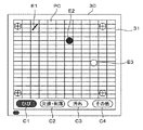
図9は、補助入力端末の表示画面を模式的に示す説明図である。
補助入力端末であるコンピュータ30のモニター31には、検査対象物である外装材4の画像PCが表示されている。モニター31における画像の表示範囲は任意に変更可能であり、例えば現在の検出箇所の周辺を拡大表示してもよい。
画像PCの下方には、検査対象物の状態を指定する状態指定ボタンC1〜C4が表示されている。ボタンC1はひび、ボタンC2は欠損・剥落、ボタンC3は汚れ、ボタンC4はその他となっている。
作業者が、検出部12を用いた作業中に目視でこれらひびや欠損、汚れ等を発見した場合、状態に対応するボタンを押下し、当該ボタンが示す状態の選択状態とする。図9の例では、ひびに対応するボタンC1が選択されている。この状態で、ひびが生じている位置に対応する画像PC上の位置にタッチすると、当該箇所にひびを示す表示E1が表示されるとともに、この位置にひびが生じていることを示す個別情報が記録される。すなわち、後述する検査対象物評価情報生成部22は、補助入力端末に入力された検出対象物の状態を個別情報として位置情報と関連付けて検査対象物評価情報を生成する。
なお、図9中符号E2は欠損・剥落を示すアイコン、符号E3は汚れを示すアイコンである。また、ひびや汚れについては、その形状をタッチペン等で書き込むようにしてもよい。
FIG. 9 is an explanatory view schematically showing a display screen of the auxiliary input terminal.
On the
Below the image PC, state designation buttons C1 to C4 for designating the state of the inspection object are displayed. The button C1 has a crack, the button C2 has a defect and peeling, the button C3 has a stain, and the button C4 has the other.
When the worker visually detects such a crack, a defect, a stain or the like while working with the
Incidentally, in FIG. 9, the symbol E2 is an icon indicating a defect / stripping, and the symbol E3 is an icon indicating a stain. Further, the shape of the crack or dirt may be written using a touch pen or the like.
また、例えば検出部12に検査対象物の状態を入力可能な状態入力部(操作ボタン等)を設けてもよい。この状態入力部は、上記状態指定ボタンC1〜C4と同様、検査対象物の状態を指定するものである。
作業者が目視でこれらひびや欠損、汚れ等を発見した場合、当該ひびや欠損、汚れ等の位置に検出部12の検出箇所を合わせた状態で該当する状態入力部を操作する。これにより、当該位置にひび等が生じていることを示す個別情報が記録される。また、撮像部17に撮像を指示する撮像トリガ信号が供給され、画像情報が生成される。すなわち、検査対象物評価情報生成部22は、検出部12が検出対象物の所定箇所にある際に状態入力部が操作された場合、当該状態入力部への操作内容に対応する検出対象物の状態を個別情報として位置情報と関連付けて検査対象物評価情報を生成する。
補助入力装置や状態入力部を用いることにより、例えば検出部12としてカメラを用いて検査対象範囲を撮像し、画像解析によりひびや欠損、汚れ等を検出するのと比較して、検査の効率を向上させることができる。
Further, for example, the
When the operator visually detects these cracks, defects, stains and the like, the corresponding state input unit is operated in a state where the detection portions of the
By using an auxiliary input device or a state input unit, for example, a camera is used as the
図1の説明に戻り、評価部14は、検出部12によって検出された、建物外面部の状態を示す個別測定情報に基づいて建物外面部の状態を評価して個別評価情報を生成するものである。
本実施の形態のように、建物躯体2に外装材4が接着されている建物外面部の場合、評価部14は、各検出箇所における浮き(建物躯体2と外装材4との剥離)やひび、欠損・剥落、汚れ等の有無を評価する。以下、上記のような好ましくない外装材4の状態を「損傷」という。
以下の説明では、主に建物躯体2に接着された外装材4の浮きを例にして説明する。なお、外装材の剥離によって形成された外装材背面側の空洞の深さの大小に基づいて、浮きの程度を評価するようにしてもよい。具体的には、空洞が外装材4の背面から距離a以上形成されている場合には「浮き有」、距離a未満b(<a)以上の場合には「軽度浮き有」、距離b未満0以上の場合には「浮きなし」のように評価してもよい。
評価部14による個別評価情報の生成は、検出部12で検出された打音および振動の検出信号の周波数、振幅、波長などの検出結果に基づいてなされ、このような個別評価情報の生成の手法として従来公知の様々な手法が採用可能である。
Returning to the explanation of FIG. 1, the
As in the present embodiment, in the case of the building outer surface where the
In the following description, the floating of the
Generation of the individual evaluation information by the
指標部16は、図2に示すように、検出部12に一体的に設けられ、本実施の形態では、検出部12の筐体1202の外面に設けられている。
指標部16は、撮像部17によって撮像可能であればよく、例えば、記号やマークが付されたシールで指標部16を構成してもよく、点灯あるいは点滅する光源で指標部16を構成してもよい。
As shown in FIG. 2, the
The
撮像部17は、指標部16と、検査対象物の表面の互いに離れた少なくとも2箇所に設定された複数の基準点とを含む範囲を撮像して画像情報を生成するものである。
撮像部17として、CCDカメラや赤外線カメラなどの静止画あるいは動画を撮像可能な従来公知の様々な撮像装置が使用可能である。
本実施の形態では、撮像部17は、検出部12により検査対象物の物理量の変化が検出された際に撮像を行い、画像情報を生成するものとする。上述のように、本実施の形態では、検出部12は検査対象物を打撃した際に生じる物理量の変化、すなわち打音および振動を検出するものであり、撮影部17は、検出部12により打音または振動が検出された際に撮像を行い、画像情報を生成するものとする。すなわち、上述した検出部12からの撮像トリガ信号に合わせて画像の撮像を行うものとする。
また、撮像部17は、常時一定の時間間隔(例えば0.1秒単位)で静止画を撮像したり、または動画を撮像するものであってもよい。また、例えば作業者の手により任意のタイミングで撮像を行ってもよい。
The
As the
In the present embodiment, it is assumed that the
In addition, the
ここで、基準点について説明する。
図2に示すように、建物躯体2に複数の外装材4としてのタイルが接着剤により接着されている。
図中、符号Aは撮像部17によって撮像可能な撮像範囲を示している。
本例では、外装材4の表面に4つの基準点P1、P2、P3、P4が設けられている。
各基準点P1、P2、P3、P4は、撮像部17によって撮像可能であればよく、例えば、記号やマークが付されたシールを外装材4の表面に設けて各基準点を構成してもよく、点灯あるいは点滅する光源を外装材4の表面に取着して各基準点を構成してもよい。
そして、各基準点P1、P2、P3、P4は、それらの距離(座標位置)が既知となっている。
例えば、基準点P1を原点(0,0)とした、この原点を通る互いに直交するX軸、Y軸を設定したときに、他の基準点P2、P3、P4の位置はX座標、Y座標の値がmm単位で既知となっている。
ここで、指標部16の位置は、各基準点P1、P2、P3、P4のうち少なくとも2つの基準点を基にして三角測量の方法によって特定することができる。
Here, the reference point will be described.
As shown in FIG. 2, tiles as a plurality of
In the drawing, reference symbol A indicates an imaging range that can be imaged by the
In this example, four reference points P1, P2, P3 and P4 are provided on the surface of the
The reference points P1, P2, P3, and P4 may be imaged by the
The distances (coordinate positions) of the reference points P1, P2, P3, and P4 are known.
For example, when the X-axis and Y-axis orthogonal to each other passing through the origin with the reference point P1 as the origin (0, 0) are set, the positions of the other reference points P2, P3 and P4 are X and Y coordinates. The value of is known in mm.
Here, the position of the
画像補正部18は、撮像部17で撮像された画像情報の歪みを補正し、補正済み画像情報を生成する。
図7は、歪みを含む画像情報を模式的に示す説明図である。
撮像部17の撮像画像は、レンズ特性等の影響により通常多少の歪みが含まれている。例えば図7Aに示す補正前画像は、下辺に比べて上辺が短い台形形状となっている。画像補正部18は、このような補正前画像を例えば台形補正を用いて補正する。すなわち、各基準点P1、P2、P3、P4は、それらの距離(座標位置)が既知となっているため、画像上の基準点の位置が既知の座標位置と一致するように補正を行う。
この結果、図7Bに示すような実際の外装材の形状に近い(歪みが少ない)画像へと補正を行うことができる。
The
FIG. 7 is an explanatory view schematically showing image information including distortion.
The captured image of the
As a result, correction can be performed to an image close to the shape of the actual exterior material (less distortion) as shown in FIG. 7B.
位置情報生成部20は、検査対象物の状態の検出がなされた時刻、本実施の形態では検出部12により外装材4を打撃した際に発生する打音および振動が検出された時刻に対応して撮像部17で撮像された画像情報(補正済み画像情報)に基づいて、複数の基準点の位置に対する指標部16の相対的な位置、すなわち検出部12の位置を示す位置情報を生成するものである。言い換えると、検出部12の位置を示す位置情報を検査対象物の検出箇所の位置情報として生成するものである。
なお、検出部12により外装材4を打撃した際に発生する打音および振動が検出された時刻に対応して撮像部17で撮像された画像情報とは、検出部12により打音および振動が検出された時刻と同時刻あるいはほぼ同時刻に撮像部17で撮像された画像情報であればよい。
なお、撮像部17で常時一定の時間間隔ごとに静止画を撮像する場合、位置情報生成部20は、撮像部17から時間経過と共に順次供給され、画像補正部18で補正された補正済み画像情報のうち、検出部12から供給されるトリガ信号に対応する画像情報を選択し、この選択された画像情報に基づいて複数の基準点の位置に対する指標部16の相対的な位置を示す位置情報を生成する。
The position
In addition, with the tapping sound and the vibration generated by the
In the case where a still image is always captured by the
上述したように、撮像部17によって撮像された画像情報上において画素単位で各基準点P1、P2、P3、P4の位置と、指標部16の位置とが特定できるので、これらの位置に基づいて三角測量の方法によって複数の基準点の位置に対する指標部16の相対的な位置を示す位置情報を生成することが可能である。この位置情報は、前述したように例えば、mm単位のX座標、Y座標の値で算出することができる。
As described above, since the positions of the reference points P1, P2, P3, and P4 and the position of the
なお、撮像部17が図4のように三脚58等に固定されており、撮像時刻が隣接する画像間で撮像範囲に変化がない場合、すべての画像で上記三角測量法に基づいて位置情報を生成するのではなく、前の画像と今回の画像とにおける指標部16の位置の差分を用いて位置情報を生成してもよい。これにより、位置情報生成部20の処理負荷を軽減することができる。
一方で、撮像部17が図5のようにゴンドラ56等に設置されており、撮像時刻が隣接する画像間で撮像範囲に変化(ぶれ)が生じる可能性がある場合、すべての画像について上記三角測量法に基づいて位置情報を生成するのが好ましい。また、このようなぶれが生じる可能性がある場合には、撮像部17の撮像範囲内に常時基準点P1、P2、P3、P4が入るように、画角を広く設定しておくのが好ましい。
In addition, when the
On the other hand, when the
位置情報補正部21は、指標部16の位置と、検出部12における検査対象物の検出箇所の位置と位置関係に基づいて、位置情報生成部20で生成された位置情報を補正する。
図8は、指標部16の位置と、検出部12の検出箇所の位置とのずれを模式的に示す説明図である。
図8は、外装材4の位置D0(検出箇所)の状態を検出部12で検出する様子を側方側から見た図である。なお、実際は外装材4に検出部12を接触させて状態の検出を行うが、図の視認性を考慮して外装材4と検出部12とを離して図示している。
検出部12による状態検出を行う場合、検出箇所となる外装材4の位置D0と、検出部12の検出位置PXとを接触させる。また、検出部12に一体的に設けられた指標部16は、外装材4に対して鉛直方向から見てその中心点DYが検出部12の検出位置PXと一致するように配置されている。
撮像部17が、指標部16に対して鉛直方向Nαに位置する場合、指標部16の中心点DYを外装材4に投影した点は検出箇所D0と一致する。一方、撮像部17が、指標部16からの鉛直方向Nαからずれた位置、例えば位置Nβに位置する場合、指標部16の中心点DYを外装材4に投影した点は検出箇所D0からずれた位置D1となり誤差の原因となる。
このため、位置情報補正部21は、指標部16の位置(中心位置)と、検出部12における検査対象物の検出箇所の位置との位置関係情報を取得する。具体的には、例えば位置情報補正部21は、検査作業の開始前に、検出部12の検出箇所を基準点P1〜P4のいずれかに合わせた状態における指標部16の画像情報上の位置と、当該基準点の実際の位置情報とに基づいて位置情報の補正量を算出する。すなわち、基準点の位置に検出部12を合わせた際の指標部16の位置情報が、既知である基準点の座標位置と一致するように補正を行う。補正の精度を向上させるため、2点以上の基準点で撮像を行い、画像情報上の全座標における補正量をそれぞれ算出するのが好ましい。
The position
FIG. 8 is an explanatory view schematically showing a deviation between the position of the
FIG. 8 is a side view showing how the
When the state detection is performed by the
When the
For this reason, the position
検査対象物評価情報生成部22は、評価部14から供給される個別評価情報と、位置情報補正部21により補正された位置情報とを関連付けた検査対象物評価情報を生成する。
また、検査対象物評価情報生成部22は、単に個別評価情報と位置情報とを関連付けるだけでなく、位置情報に基づく評価情報を生成してもよい。具体的には、例えば外装材4の損傷面積や損傷枚数(タイル等の場合)等を算出してもよい。すなわち、以下に説明するように、検査対象物評価情報生成部22は、損傷があると判断された検出箇所を含む単位外装材の損傷枚数および当該枚数に単位面積を掛け合せた損傷面積を検査対象物評価情報として生成してもよい。
The inspection object evaluation
Further, the inspection object evaluation
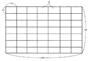
図10〜図12は、位置情報に基づく評価情報の生成方法を模式的に示す説明図である。
作業者は、予め外装材4の最小単位寸法および配列方法について検査対象物評価情報生成部22に入力しておく。図10に示すように、外装材4がタイル等の矩形部材である場合、縦方向の寸法LY、横方向の寸法LX、および配列(図10に示すような縦横の配列が揃ったグリッドタイプか、縦方向の配列をずらしたレンガ積タイプか)を入力する。
また、作業者は、検査対象物全体の寸法も検査対象物評価情報生成部22に入力しておく。図10の例では検査対象物の縦寸法LH、横寸法LWを入力する。
検査対象物評価情報生成部22は、これらの情報に基づいて検査対象物上のタイルの枚数および配置位置を算出する。すなわち、横方向のタイル枚数は、検査対象物の横寸法LW/タイルの横寸法LXにより算出することができる。なお、端数が生じた場合には、例えば目地幅として処理する。作業者が目地幅を入力するようにしてもよい。また、縦方向のタイル枚数は、検査対象物の縦寸法LH/タイルの縦寸法LYにより算出することができる。この場合も、端数が生じた場合には、例えば目地幅として処理する。検査対象物全体のタイル枚数は、横方向のタイル枚数×縦方向のタイル枚数により算出することができる。これらの枚数のタイルを検査対象物の寸法上に均等配置することにより、外装材4(タイル)の配置状態を再現することができる。
なお、このような外装材4(タイル)の配置状態を、撮像部17で撮像した画像から画像解析により把握するようにしてもよい。
10 to 12 are explanatory views schematically showing a method of generating evaluation information based on position information.
The operator inputs in advance the inspection object evaluation
In addition, the worker also inputs the dimensions of the entire inspection object into the inspection object evaluation
The inspection object evaluation
Note that such an arrangement state of the exterior material 4 (tile) may be grasped from the image captured by the
このように外装材4(タイル)の配置状態を再現することにより、検査対象物上の任意の位置座標がどのタイル上にあるかを特定することができる。
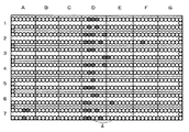
図11は、個別評価情報を位置情報に合わせてプロットした図である。図11の例では、個別評価情報としてタイル浮きの有無をプロットしており、各丸印が個々の個別評価情報を示す。網掛けがあるプロットは浮きが検出された(タイル背面に深さ方向の距離a以上の空洞が検出された)ことを示し、網掛けがないプロットは浮きが検出されなかったことを示す。
個別評価情報のみのプロットでは、浮き箇所の分布を把握できるのみであるが、タイルの配置状態と重ねることにより、浮きの生じているタイルの箇所や枚数、面積等を算出することができる。
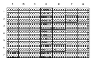
タイルの縦方向の配列にA〜G、縦方向の配列に1〜7を付番し、例えば最左上のタイルをA1、最右下のタイルをG7とすると、図12に示すように、太枠で囲んだ11枚のタイル(A7、D1、D2、D3、D4、D5、D6、D7、E3、E6、F2)に浮きが生じていることがわかる。また、浮きがあるタイル数11にタイル1枚当たりの面積を掛けあわせることにより、浮きが生じている面積を算出することができる。
なお、上述した例では、1箇所でも浮きが検出された場合には当該タイルを不良(浮き有)と判定しているが、不良と判定する際の検出箇所数を設定できるようにしてもよい。
By reproducing the arrangement state of the exterior material 4 (tiles) in this manner, it is possible to specify on which tile arbitrary position coordinates on the inspection object are present.
FIG. 11 is a diagram in which the individual evaluation information is plotted in accordance with the position information. In the example of FIG. 11, the presence or absence of tile floating is plotted as individual evaluation information, and each circle indicates individual individual evaluation information. A shaded plot indicates that float was detected (a cavity at a distance a in the depth direction was detected on the back of the tile), and a non-shaded plot indicates that float was not detected.
In the plot of only the individual evaluation information, only the distribution of the floating part can be grasped, but by overlapping with the arrangement state of the tile, it is possible to calculate the location, number, area and the like of the tile in which floating occurs.
Let A to G be the vertical array of tiles, and 1 to 7 the vertical arrays. For example, assuming the top left tile is A1 and the bottom right tile is G7, as shown in FIG. It can be seen that the 11 tiles (A 7,
In the example described above, the tile is determined to be defective (floating) when floating is detected even in one place, but the number of detection points when it is determined to be defective may be set. .
検査対象物評価情報生成部22は、例えば個別情報と位置情報とを関連付けたデータファイルとして検査対象物評価情報を生成する。検査対象物評価情報生成部22は、例えばCSVファイル形式で検査対象物評価情報を生成する。これにより、検査対象物評価情報の汎用性を向上させることができる。
図13は、検査対象物評価情報が記録されたCSVファイルの出力例を示す説明図である。
実際のCSVデータファイルは、カンマで区切られたデータが記録されているが、例えば図13に示すような表形式で各種データを出力することも可能となる。
図13の表には、壁面番号1301、タイル配列タイプ(グリッドタイプの場合はA、レンガ積タイプの場合はB)1302、浮き有のタイル数1303およびその面積1304、軽度浮き有のタイル数1305およびその面積1306、欠損・剥落有のタイル数1307およびその面積1308、ひび割れ有のタイル数1309およびその面積1310、汚れ有のタイル数1311およびその面積1312、画像フォルダの保存場所1313、1314等が記載されている。
表形式の出力を可能とすることで、メンテナンスが必要なタイルの数や面積を状態別に把握することができ、利便性を向上することができる。
このように、検査対象物評価情報をデータファイルとして生成することにより、後述する表示部26での表示以外にも検査対象物評価情報を使用することができ、検査対象物評価情報の有用性を向上させることができる。
The inspection object evaluation
FIG. 13 is an explanatory view showing an output example of a CSV file in which inspection object evaluation information is recorded.
In the actual CSV data file, data separated by commas is recorded, but it is also possible to output various data in a tabular format as shown in FIG. 13, for example.
In the table of FIG. 13,
By enabling tabular output, the number and area of tiles requiring maintenance can be grasped for each state, and convenience can be improved.
Thus, by generating inspection object evaluation information as a data file, inspection object evaluation information can be used other than the display on the
記憶部24は、補正済み画像情報と検査対象物評価情報とを関連付けて記憶するものである。なお、補正前の画像情報を共に保存しておいてもよい。
The
表示部26は、画像を表示するものである。
表示制御部28は、表示部26に各種情報を表示させるものである。
表示制御部28は、画像情報に基づいて建物外面の画像を表示部26に表示させると共に、検査対象物評価情報に含まれる位置情報によって特定される建物外面の画像上の箇所に、検査対象物評価情報に含まれ位置情報に関連付けられた個別評価情報を表示させる。すなわち、表示部26に表示された建物外面の画像に重ね合わせて個別評価情報を表示させる。
具体的には、図11に示すような表示がなされることになる。図11の例では、浮きの有無についての表示例であるが、状態評価装置10のインターフェースを適宜操作することにより、他の損傷、例えばひびや欠損、汚れの生じている箇所をそれぞれ表示可能である。またはそれら損傷の状態を全て重畳して表示部26に表示してもよい。
このような表示は、例えば記憶部24に記憶されている建物外面の補正済み画像を複製し、複製した画像上に個別評価情報に対応するアイコンなどを直接描画することによって行う。表示後は、個別評価情報が書き込まれた画像を記憶部24に保存してもよい。
表示部26による個別評価情報の表示は、例えば個別評価情報をその評価内容に対応付けられた複数種類の色を呈するマークで表示することによっておこなう。より詳細には、例えば外装材4の浮きが有る箇所は赤色のマークで、外装材4の浮きが無い箇所は青色のマークで表示するなどである。
また、外装材4の浮きの度合いが大きいほど(背面の空洞が深いほど)赤色の濃度を濃くし、外装材4の浮きの度合いが小さいほど(背面の空洞が浅いほど)赤色の濃度を薄くしたマークで表示するようにしてもよい。
なお、評価結果の表示は色の濃淡や種類によって限定されるものではなく、建物外面部の状態の検出結果を示す生データや建物外面部の状態の検出結果を表す数値や建物外面部の状態の検出結果を表す情報など従来公知の様々な方法を選択してもよい。
The
The
The
Specifically, the display as shown in FIG. 11 is made. Although the example of FIG. 11 is a display example regarding the presence or absence of floating, by appropriately operating the interface of the
Such display is performed, for example, by duplicating the corrected image of the building outer surface stored in the
The display of the individual evaluation information by the
Also, the red density increases as the degree of floating of the
In addition, the display of the evaluation result is not limited by the shade or color of the color, and the raw data indicating the detection result of the state of the building outer surface or the numerical value indicating the detection result of the state of the building outer surface or the state of the building outer surface Various methods known in the art such as information representing the detection result of the above may be selected.
図1に示すように、評価部14、画像補正部18、位置情報生成部20、位置情報補正部21、検査対象物評価情報生成部22、記憶部24、表示部26、表示制御部28は、コンピュータ30によって構成することができる。
コンピュータ30は、例えば、作業員が携帯可能なタブレット端末で構成され、検出部12とケーブルで接続されている。
コンピュータ30は、CPU、ROM、RAM、タッチパネル、ディスプレイ装置、入出力インターフェースなどを有している。
ROMは例えばフラッシュメモリなどで構成され、制御プログラムなどを格納し、RAMはワーキングエリアを提供するものである。
CPUが制御プログラムを実行することで評価部14、画像補正部18、位置情報生成部20、位置情報補正部21、検査対象物評価情報生成部22、表示制御部28が実現される。
また、ROMあるいはRAMは記憶部24として機能する。
また、キーボードおよびマウスは、操作者による操作入力を受け付けるものである。
ディスプレイ装置は、画像を表示するものであり、例えば、液晶表示装置などで構成される。ディスプレイ装置は表示部26として機能する。
As shown in FIG. 1, the
The
The
The ROM is configured by, for example, a flash memory and stores a control program and the like, and the RAM provides a working area.
The execution of the control program by the CPU realizes the
The ROM or RAM functions as the
Further, the keyboard and the mouse are for receiving operation input by the operator.
The display device displays an image, and is configured of, for example, a liquid crystal display device. The display device functions as the
次に、図3のフローチャートを参照して状態評価装置10の動作について説明する。
まず、図2に示すように、評価対象となる建物躯体2に設けられた外装材4の表面に複数の基準点P1、P2、P3、P4を設置する(ステップS10)。
この際、各基準点P1、P2、P3、P4の位置は実測されており既知となっている。
次に、撮像部17によって撮像される撮像範囲Aに、各基準点P1、P2、P3、P4の全てが撮像されるように撮像部17を設置する(ステップS12)。
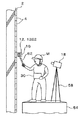
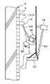
図4に、建物躯体2の近傍に足場54を構築し、作業者Mが足場54を利用して建物外面部に対する検出作業を行なう場合の例を示し、図5に、作業者Mが建物上部から吊り下げられたゴンドラ56を利用して建物外面部に対する検出作業を行なう場合の例を示す。
図4に示す例では、足場54上に設置した三脚58に取り付けた撮像部17を用いて撮像範囲Aの撮像を行なう。図5に示す例では、ゴンドラ56に設けた支持部材60に取着した撮像部17を用いて撮像範囲Aの撮像を行なう。
Next, the operation of the
First, as shown in FIG. 2, a plurality of reference points P1, P2, P3 and P4 are installed on the surface of the
At this time, the positions of the reference points P1, P2, P3 and P4 are measured and known.
Next, the
FIG. 4 shows an example where a
In the example shown in FIG. 4, imaging of the imaging range A is performed using the
作業者は、検出部12を診断対象となる外装材4の表面に当接させる(ステップS14)。
なお、図4、図5に示すように、検出部12の筐体1202に支持棒62の先端が取着されており、作業者Mは支持棒62を把持することにより検出部12を広い範囲にわたって容易に移動できるように図られている。
The worker brings the
As shown in FIGS. 4 and 5, the tip of the
次に、作業者Mが検出部12を操作することにより、外装材4の表面が打撃され打音や振動が検出され、その検出結果(検出信号)が評価部14に供給される(ステップS16,S18)。また、検出部12により検出を行うと同時に、打音や振動の検出に合わせて撮像部17で画像の撮像が行われる(ステップS19)。撮像された画像は、画像補正部18により台形補正等が施される(ステップS20)。
Next, when the worker M operates the
評価部14は、検出結果に基づいて外装材4の損傷、例えば浮きの有無を判定すると共に、外装材背面に形成された空洞の深さに基づいて浮きの程度を判定する。
すなわち、評価部14は、建物外面部の状態を評価する個別評価情報としての外装材4の損傷の有無および損傷の程度を生成する(ステップS21)。
The
That is, the
位置情報生成部20は、検出部12による建物外面部の状態の検出がなされた時刻に対応して撮像部17で撮像された画像情報に基づいて、複数の基準点P1、P2、P3、P4の位置に対する指標部16の相対的な位置を示す位置情報を生成する(ステップS22)。
検査対象物評価情報生成部22は、個別評価情報と位置情報とを関連付けた検査対象物評価情報を生成し、(ステップS24)、生成された検査対象物評価情報は記憶部24に格納される(ステップS26)。
作業者Mは、次に評価を行なうべき外面箇所の有無を判断し(ステップS28)、次に評価すべき外面箇所があれば、ステップS14に戻り同様の検出動作を行なう。次に評価すべき外面箇所が無ければ、すなわち、撮像範囲Aにおける建物外面部の状態の検出が全て完了したならば、コンピュータ30のキーボードあるいはマウスを操作することで一連の操作が終了した旨を表示部26に報知する。
これにより、表示制御部28は、記憶部24に格納されている画像情報に基づいて建物躯体2の画像を表示部26に表示させると共に、記憶部24に格納されている位置情報によって特定される建物躯体2の画像上の箇所に、位置情報に関連付けられた個別評価情報を表示させ(ステップS30)、一連の動作を終了する。
The position
The inspection object evaluation
The operator M determines the presence or absence of an outer surface location to be evaluated next (step S28), and if there is an outer surface location to be evaluated next, returns to step S14 and performs the same detection operation. If there is no outer surface to be evaluated next, that is, if detection of the state of the building outer surface in the imaging range A is all completed, the keyboard or mouse of the
Thus, the
この結果、例えば損傷が浮きである場合には、外装材4の浮きが有る箇所は赤色のマークが当該外装材4の画像に重ね合わせて表示される。また、外装材4の浮きが無い箇所は青色のマークが当該外装材4の画像に重ね合わせて表示される。
また、外装材4の浮きの程度が大きい(背面の空洞が深い)ほど赤色の濃度が濃いマークで表示され、外装材4の浮きの程度が小さい(背面の空洞が浅い)ほど赤色の濃度を薄くしたマークで表示される。
例えば、空洞の深さが5mm未満であれば薄い赤色、5mm以上であれば濃い赤色といったように表示される。なお、濃度は2段階に限定されず3段階以上であってもよい。
また、空洞の深さを示す数値を当該外装材4の画像に重ね合わせて表示してもよい。
As a result, for example, in the case where the damage is floating, a red mark is superimposed on the image of the
Also, the higher the degree of floating of the exterior material 4 (the deeper the back cavity), the higher the density of red is displayed, and the smaller the degree of floating of the exterior material 4 (the shallower back cavity) the higher the red density. Displayed with a dimmed mark.
For example, if the depth of the cavity is less than 5 mm, it is displayed as light red, and if 5 mm or more, it is displayed as deep red. The concentration is not limited to two but may be three or more.
Also, a numerical value indicating the depth of the cavity may be superimposed on the image of the
なお、本実施の形態では、画像情報と位置情報と個別評価情報とを表示部26の表示画面上に表示する場合について説明したが、コンピュータにプリンタ装置を接続し、画像情報と位置情報と個別評価情報とを印刷媒体上に印刷により表示させるようにしてもよいことは無論である。この場合、表示部26はプリンタ装置によって構成されることになる。
In the present embodiment, the image information, the position information, and the individual evaluation information are displayed on the display screen of the
以上説明したように本実施の形態によれば、検出部12による検査対象物の状態の検出結果またはその検出結果に基づいて生成される評価結果を示す個別情報と、検査対象物の状態の検出がなされた時刻に対応して撮像された画像情報に基づいて、複数の基準点の位置に対する検出部12の相対的な位置を示す位置情報を検査対象物の検出箇所の位置情報として生成する。そして、個別情報と位置情報とを関連付けた検査対象物評価情報を生成するようにした。
したがって、個別情報と位置情報とを関連付けた評価を短時間で的確に行いつつ構成の簡素化を図る上で有利となる。
また、画像情報および位置情報の補正を行うので、撮像画像に含まれる歪みや光学的誤差を補正してより精度よく検査対象物の検査を行う上で有利となる。
As described above, according to the present embodiment, the individual information indicating the detection result of the state of the inspection object by the
Therefore, it is advantageous in simplifying the configuration while accurately performing the evaluation in which the individual information and the position information are associated in a short time.
Further, since the correction of the image information and the position information is performed, it is advantageous in correcting the distortion and the optical error included in the captured image to inspect the inspection object more accurately.
また、本実施の形態によれば、検査対象物評価情報をCSVファイルとして出力するので、検査対象物評価情報の汎用性を高めて検査の有用性を向上させる上で有利となる。
また、本実施の形態によれば、撮像部17は検出部12により打音または振動が検出された際に撮像を行うので、一定間隔で常時撮像を行う場合と比較して、撮像部17の電力消費量を軽減するとともに、個別情報に対応する画像を特定しやすくする上で有利となる。
また、本実施の形態において、検査対象物の画像上にその状態を入力可能な補助入力端末または検査対象物の状態を入力可能な状態入力部を設けるようにすれば、検査作業をより効率的に行う上で有利となる。
また、本実施の形態によれば、表示部26に検査対象物の表面の画像を表示させ、その上に個別情報を重畳して表示するので、検査対象物の状態を効率よく評価する上で有利となる。
また、本実施の形態によれば、建物躯体2に接着された外装材4の損傷の有無を評価するので、外装材の損傷の有無を効率的よく評価する上で有利となる。
また、本実施の形態によれば、損傷がある外装材4の枚数および損傷面積を検査対象物評価情報として生成するので、検査対象物の損傷状態をより直感的に把握可能とする上で有利となる。
Moreover, according to the present embodiment, the inspection object evaluation information is output as a CSV file, which is advantageous in enhancing the versatility of the inspection object evaluation information and improving the usefulness of inspection.
Further, according to the present embodiment, since the
Further, in the present embodiment, by providing an auxiliary input terminal capable of inputting the state on the image of the inspection object or a state input unit capable of inputting the state of the inspection object, the inspection work can be made more efficient. It is advantageous to do.
Further, according to the present embodiment, since the image of the surface of the inspection object is displayed on the
Further, according to the present embodiment, the presence or absence of damage to the
Further, according to the present embodiment, the number of damaged
(第2の実施の形態)
次に第2の実施の形態について図6を参照して説明する。
なお、以下の実施の形態において、第1の実施の形態と同様の部分、部材については同一の符号を付してその説明を省略する。
第1の実施の形態では、評価対象となる建物外面の全域が撮像部17の撮像範囲内に収まる場合について説明した。
第2の実施の形態では、建物外面が大きく、建物外面の全域が撮像部17の撮像範囲内に収まり切れない場合について説明する。
具体的には、図6に示すように、建物外面の面積が撮像部17の撮像範囲よりも大きいため、撮像部17の撮像範囲を第1の範囲と第2の範囲との2つの範囲に移動させて、それぞれの範囲において建物外面部の状態の検出を行なう。
Second Embodiment
Next, a second embodiment will be described with reference to FIG.
In the following embodiments, the same parts and members as those in the first embodiment are denoted by the same reference numerals, and the description thereof is omitted.
In the first embodiment, the case where the entire area of the building outer surface to be evaluated falls within the imaging range of the
In the second embodiment, the case where the building outer surface is large and the entire area of the building outer surface can not fit within the imaging range of the
Specifically, as shown in FIG. 6, since the area of the building outer surface is larger than the imaging range of the
まず、評価対象となる建物外面に設けられた外装材4の表面に複数の基準点P1、P2、P3、P4を設置する。これら複数の基準点P1、P2、P3、P4により第1の基準点が構成される。この際、撮像部17によって撮像される撮像範囲は第1の範囲A1であり、第1の範囲A1内に、各第1の基準点P1、P2、P3、P4の全てが撮像されるように撮像部17を設置する。
そして、第1の実施の形態と同様の要領によって第1の範囲A1に対する建物外面部の状態の検出および評価を行なう。
第1の範囲A1に対する建物外面部の状態の検出が終了したならば、撮像部17により撮像される撮像範囲を第1の範囲A1から第1の範囲A1に隣接する第2の範囲A2に移動し、かつ、第1の範囲A1と第2の範囲A2とが互いに重複する重複範囲Bを含むように撮像部17を移動させる。
ここで、予め、重複範囲Bには、複数の第1の基準点P3、P4が含まれるように第2の範囲A2を設定する。
さらに、重複範囲Bを除く第2の範囲A2に1以上の基準点で構成される第2の基準点P5、P6を設置する。
First, a plurality of reference points P1, P2, P3 and P4 are installed on the surface of the
Then, detection and evaluation of the state of the building outer surface with respect to the first range A1 are performed in the same manner as in the first embodiment.
When the detection of the state of the building outer surface with respect to the first range A1 is completed, the imaging range imaged by the
Here, the second range A2 is set in advance so that the overlapping range B includes the plurality of first reference points P3 and P4.
Further, in the second range A2 excluding the overlapping range B, second reference points P5 and P6 configured of one or more reference points are installed.
そして、撮像部17により第2の範囲A2が撮像した状態で、位置情報生成部20は、重複範囲Bに位置する複数の基準点P3、P4で構成される第1の基準点に基づいて重複範囲Bを除く第2の範囲A2に位置する1以上の基準点P5、P6で構成される第2の基準点の位置を特定する。
これにより位置情報生成部20は、第2の範囲における位置情報の生成を、第2の基準点の位置を用いて行なう。
以下、第1の実施の形態と同様の要領によって第2の範囲A2に対する建物外面部の状態の検出および評価を行なう。
Then, in a state in which the second range A2 is imaged by the
Thus, the position
Hereinafter, detection and evaluation of the state of the building outer surface with respect to the second range A2 are performed in the same manner as in the first embodiment.
第2の実施の形態によれば、重複範囲Bに位置する複数の基準点で構成される第1の基準点に基づいて重複範囲Bを除く第2の範囲A2に位置する1以上の基準点で構成される第2の基準点の位置を特定し、位置情報生成部20による第2の範囲A2における位置情報の生成を第2の基準点の位置を用いて行なうようにした。
したがって、第2の範囲A2における第2の基準点の位置が既知でなくても第2の範囲A2における位置情報を正確に検出できるため、広範囲にわたって建物外面部の状態の検出および評価を効率よく行なう上で有利となる。
なお、本実施の形態では、撮像部17の撮像範囲を第1の範囲A1と第2の範囲A2との2つの範囲に移動させて建物外面部の状態の検出および評価を行なう場合について説明したが、撮像部17の撮像範囲を3つ以上の範囲に移動させて建物外面部の状態の検出および評価を行なうようにしてもよい。
この場合は、撮像部17の撮像範囲を現在の範囲から次の範囲に移動させる毎に、重複範囲を除く次の範囲に新たな基準点(第2の基準点)を設置し、現在の範囲と次の範囲との重複範囲に位置する基準点(第1の基準点)に基づいて、新たな基準点(第2の基準点)の位置を特定し、特定した新たな基準点(第2の基準点)を用いて次の範囲における位置情報の生成を行えば良い。
According to the second embodiment, one or more reference points located in the second range A2 excluding the overlapping range B based on the first reference points formed by the plurality of reference points located in the overlapping range B The position of the second reference point configured by the above is specified, and the generation of the position information in the second range A2 by the position
Therefore, even if the position of the second reference point in the second range A2 is not known, the position information in the second range A2 can be accurately detected, so that the state of the building outer surface part can be detected and evaluated efficiently over a wide range. It is advantageous to do.
In the present embodiment, the case where the state of the building outer surface portion is detected and evaluated by moving the imaging range of the
In this case, every time the imaging range of the
(第3の実施の形態)
次に第3の実施の形態について説明する。
第2の実施の形態では、第1の基準点がP1、P2、P3、P4の4つの基準点で構成され、第2の基準点がP5,P6の2点の基準点で構成されている場合について説明したが、第1の基準点は少なくとも3つあればよく、第2の基準点は少なくとも1つあればよい。
以下、図6を流用して説明する。
基準点P2、P5は無いものとする。
評価対象となる建物外面に設けられた外装材4の表面に複数の基準点P1、P3、P4を設置する。これら複数の基準点P1、P3、P4により第1の基準点が構成される。この際、撮像部17によって撮像される撮像範囲は第1の範囲A1であり、第1の範囲A1内に、各第1の基準点P1、P3、P4の全てが撮像されるように撮像部17を設置する。
そして、第1の実施の形態と同様の要領によって第1の範囲A1に対する建物外面部の状態の検出および評価を行なう。
第1の範囲A1に対する建物外面部の状態の検出が終了したならば、撮像部17により撮像される撮像範囲を第1の範囲A1から第1の範囲A1に隣接する第2の範囲A2に移動し、かつ、第1の範囲A1と第2の範囲A2とが互いに重複する重複範囲Bを含むように撮像部17を移動させる。
ここで、予め、重複範囲Bには、複数の第1の基準点P3、P4が含まれるように第2の範囲A2を設定する。
さらに、重複範囲Bを除く第2の範囲A2に1つの第2の基準点P6を設置する。
Third Embodiment
Next, a third embodiment will be described.
In the second embodiment, the first reference point is composed of four reference points P1, P2, P3 and P4, and the second reference point is composed of two reference points P5 and P6. Although the case has been described, there may be at least three first reference points and at least one second reference point.
Hereinafter, description will be made with reference to FIG.
It is assumed that there are no reference points P2 and P5.
A plurality of reference points P1, P3 and P4 are installed on the surface of the
Then, detection and evaluation of the state of the building outer surface with respect to the first range A1 are performed in the same manner as in the first embodiment.
When the detection of the state of the building outer surface with respect to the first range A1 is completed, the imaging range imaged by the
Here, the second range A2 is set in advance so that the overlapping range B includes the plurality of first reference points P3 and P4.
Furthermore, one second reference point P6 is set in the second range A2 excluding the overlapping range B.
そして、撮像部17により第2の範囲A2が撮像した状態で、位置情報生成部20は、重複範囲Bに位置する複数の基準点P3、P4で構成される第1の基準点に基づいて重複範囲Bを除く第2の範囲A2に位置する1つの基準点P6で構成される第2の基準点の位置を特定する。
これにより位置情報生成部20は、第2の範囲における位置情報の生成を、第2の基準点P6の位置を用いて行なう。
以下、第1の実施の形態と同様の要領によって第2の範囲A2に対する建物外面部の状態の検出および評価を行なう。
第3の実施の形態においても第2の実施の形態と同様の効果が奏される。
Then, in a state in which the second range A2 is imaged by the
Thus, the position
Hereinafter, detection and evaluation of the state of the building outer surface with respect to the second range A2 are performed in the same manner as in the first embodiment.
Also in the third embodiment, the same effect as that of the second embodiment can be obtained.
なお、実施の形態では、検査対象物が建物であり、タイルなどの外装材4の浮きや剥がれなどの接着状態を評価する場合について説明したが、本発明は、タイルやモルタルなどの外装材が設けられていない場合には、建物外面に加え、この建物外面近くの内部の状態を評価する場合、また、タイルやモルタルなどの外装材が設けられている場合には、外装材の表面に加え、外装材の表面の内側の外装材部分や外装材の内側の建物躯体の表面や表面近くの内部を評価する場合に広く適用可能である。
さらに、本発明は、建物の室内の床、天井、壁面、室内のコンクリート躯体などを評価する場合に広く適用可能である。
また、本発明は、検査対象物が建物に限定されず、高架橋やダムなどの構造物などを評価する場合に広く適用可能である。
In the embodiment, the inspection object is a building and the case of evaluating the adhesion state such as floating or peeling of the
Furthermore, the present invention can be widely applied to the case of evaluating the floor, ceiling, wall surface, indoor concrete frame and the like of the interior of a building.
Moreover, this invention is not limited to a test object, and it is widely applicable, when evaluating structures, such as a viaduct and a dam, not only a building.
また、実施の形態では、建物外面部の状態の検出結果に基づいて生成される評価結果を示す個別評価情報と、検査対象物の検出箇所の位置を示す位置情報とを関連付けた検査対象物評価情報を生成し、また、検査対象物評価情報に含まれる位置情報によって特定される建物外面の画像上の箇所に、検査対象物評価情報に含まれ位置情報に関連付けられた個別評価情報を表示部26に表示させる場合について説明した。この場合、個別評価情報は本発明の個別情報に相当する。
しかしながら、個別評価情報に代えて建物外面部の状態の検出結果を示す個別測定情報と、検査対象物の検出箇所の位置を示す位置情報とを関連付けた検査対象物評価情報を生成し、また、検査対象物評価情報に含まれる位置情報によって特定される建物外面の画像上の箇所に、検査対象物評価情報に含まれ位置情報に関連付けられた個別測定情報を表示部26に表示させるようにしてもよい。この場合、個別測定情報は本発明の個別情報に相当する。
Further, in the embodiment, an inspection object evaluation that associates individual evaluation information indicating an evaluation result generated based on a detection result of a state of a building outer surface with position information indicating a position of a detection point of the inspection object. Information is generated, and individual evaluation information included in inspection object evaluation information and associated with the position information is displayed at a location on the image of the building outer surface specified by the position information included in the inspection object evaluation information The case of displaying on 26 has been described. In this case, the individual evaluation information corresponds to the individual information of the present invention.
However, instead of the individual evaluation information, inspection object evaluation information is generated in which individual measurement information indicating the detection result of the state of the building outer surface is associated with position information indicating the position of the detection point of the inspection object. The individual measurement information included in the inspection object evaluation information and associated with the position information is displayed on the
例えば、建物外面部の状態として温度を検出する場合、温度の測定値(生データ)を個別測定情報として扱い、温度の測定値(個別測定情報)と検出箇所の位置を示す位置情報とを関連付けた検査対象物評価情報を生成し、検査対象物評価情報に含まれる位置情報によって特定される建物外面の画像上の箇所に、検査対象物評価情報に含まれ位置情報に関連付けられた温度の測定値(個別測定情報)を表示部26に表示させるようにしてもよい。
このようにすると、検出部12によって検出された建物外面部の状態を示す個別測定情報そのものを評価する上で有利となる。
For example, when temperature is detected as the state of the building outer surface, the measured value of temperature (raw data) is treated as individual measurement information, and the measured value of temperature (individual measurement information) is associated with position information indicating the position of the detection location. Of the inspection object evaluation information and measuring the temperature included in the inspection object evaluation information and associated with the position information at the location on the image of the building outer surface specified by the position information included in the inspection object evaluation information The value (individual measurement information) may be displayed on the
This is advantageous in evaluating the individual measurement information itself indicating the state of the building outer surface detected by the
また、温度の測定値(個別測定情報)と検査対象物の検出箇所の位置を示す位置情報とを関連付けた検査対象物評価情報を生成したのち、検査対象物評価情報に含まれる個別測定情報に基づいて評価を行い、その評価結果を個別評価情報として生成し、この個別評価情報を検査対象物評価情報に含まれる位置情報と関連付けるようにしてもよい。この場合、検査対象物評価情報に含まれる位置情報によって特定される建物外面の画像上の箇所に、位置情報に関連付けられた個別評価情報を表示部26に表示させるようにしてもよい。
このようにすると、個別測定情報を評価した個別評価情報に基づいて建物外面部の状態を的確に評価する上で有利となる。
In addition, after generating inspection object evaluation information in which the measured value of temperature (individual measurement information) and the position information indicating the position of the detection point of the inspection object are associated, individual measurement information included in the inspection object evaluation information The evaluation may be performed based on the evaluation result, the evaluation result may be generated as individual evaluation information, and the individual evaluation information may be associated with the position information included in the inspection object evaluation information. In this case, the individual evaluation information associated with the position information may be displayed on the
In this way, it is advantageous to accurately evaluate the state of the building exterior based on the individual evaluation information obtained by evaluating the individual measurement information.
2 建物躯体
4 外装材
10 状態評価装置
12 検出部
14 評価部
16 指標部
17 撮像部
18 画像補正部
20 位置情報生成部
21 位置情報補正部
22 検査対象物評価情報生成部
24 記憶部
26 表示部
28 表示制御部
30 コンピュータ
Claims (11)
前記検査対象物の状態を検出する検出部と、
前記検出部に一体的に設けられた指標部と、
前記指標部と、前記検査対象物の表面の互いに離れた少なくとも2箇所に設定された複数の基準点とを含む範囲を撮像して画像情報を生成する撮像部と、
前記撮像部で撮像された前記画像情報の歪みを補正し、補正済み画像情報を生成する画像補正部と、
前記検査対象物の状態の検出がなされた時刻に撮像された前記画像情報に対応する前記補正済み画像情報に基づいて、前記複数の基準点の位置に対する前記指標部の相対的な位置を示す位置情報を前記検査対象物の検出箇所の位置情報として生成する位置情報生成部と、
前記指標部の位置と、前記検出部における前記検査対象物の検出箇所の位置との位置関係に基づいて前記位置情報を補正する位置情報補正部と、
前記個別情報と補正された前記位置情報とを関連付けた検査対象物評価情報を生成する検査対象物評価情報生成部と、
を備えることを特徴とする検査対象物の状態評価装置。 State evaluation of the inspection object in which individual information indicating the detection result of the state of the inspection object or the evaluation result generated based on the detection result is associated with position information indicating the position of the detection point of the inspection object A device,
A detection unit that detects a state of the inspection object;
An indicator unit provided integrally with the detection unit;
An imaging unit configured to image an area including the index unit and a plurality of reference points set at least two places apart from each other on the surface of the inspection object to generate image information;
An image correction unit that corrects distortion of the image information captured by the imaging unit and generates corrected image information;
A position indicating the relative position of the indicator with respect to the positions of the plurality of reference points based on the corrected image information corresponding to the image information captured at the time when the state of the inspection object is detected A position information generation unit that generates information as position information of a detected position of the inspection object;
A position information correction unit that corrects the position information based on a positional relationship between the position of the index unit and the position of the detection portion of the inspection object in the detection unit;
An inspection object evaluation information generation unit that generates inspection object evaluation information in which the individual information and the corrected position information are associated with each other;
An apparatus for evaluating the condition of an inspection object, comprising:
前記位置情報補正部は、前記検出部の検出箇所をいずれかの前記基準点に合わせた状態における前記指標部の前記画像情報上の位置と、前記基準点の位置情報とに基づいて前記位置関係情報を算出する、
ことを特徴とする請求項1記載の検査対象物の状態評価装置。 The position information of the reference point is known,
The positional information correction unit is configured to determine the positional relationship based on the position on the image information of the indicator unit and the positional information on the reference point in a state in which the detection point of the detection unit is aligned with any of the reference points. Calculate information,
The state evaluation device for an inspection object according to claim 1, characterized in that
ファイルとして前記検査対象物評価情報を出力する、
ことを特徴とする請求項1または2記載の検査対象物の状態評価装置。 The inspection object evaluation information generation unit outputs the inspection object evaluation information as a data file in which the individual information is associated with the position information.
The condition evaluation device for the inspection object according to claim 1 or 2, characterized in that:
前記撮像部は、前記検出部により前記物理量の変化が検出された際に撮像を行い、前記画像情報を生成する、
ことを特徴とする請求項1から3のいずれか1項記載の検査対象物の状態評価装置。 The detection unit detects a physical quantity around the inspection object,
The imaging unit performs imaging when the change in the physical quantity is detected by the detection unit, and generates the image information.
The state evaluation device of the inspection object according to any one of claims 1 to 3, characterized in that.
ことを特徴とする請求項4記載の検査対象物の状態評価装置。 The detection unit detects a change in the physical quantity that occurs when the inspection object is struck.
The apparatus for evaluating the state of an inspection object according to claim 4, wherein
前記検査対象物評価情報生成部は、前記補助入力端末に入力された前記検出対象物の状態を前記個別情報として前記位置情報と関連付けて前記検査対象物評価情報を生成する、
ことを特徴とする請求項1から5のいずれか1項記載の検査対象物の状態評価装置。 An auxiliary input terminal that can display the corrected image, specify a predetermined location on the corrected image, and can input the state of the location of the detection target corresponding to the predetermined location.
The inspection object evaluation information generation unit associates the state of the detection object input to the auxiliary input terminal with the position information as the individual information to generate the inspection object evaluation information.
The state evaluation device of the inspection object according to any one of claims 1 to 5, characterized in that.
前記検査対象物評価情報生成部は、前記検出部が前記検出対象物の所定箇所にある際に前記状態入力部が操作された場合、当該状態入力部への操作内容に対応する前記検出対象物の状態を前記個別情報として前記位置情報と関連付けて前記検査対象物評価情報を生成する、
ことを特徴とする請求項1から5のいずれか1項記載の検査対象物の状態評価装置。 The detection unit further includes a state input unit capable of inputting the state of the inspection object;
When the state input unit is operated when the detection unit is at a predetermined position of the detection object, the inspection object evaluation information generation unit corresponds to the detection object corresponding to the content of the operation on the state input unit. The inspection object evaluation information is generated in association with the position information as the individual information.
The state evaluation device of the inspection object according to any one of claims 1 to 5, characterized in that.
前記補正済み画像情報に基づいて前記検査対象物の表面の画像を前記表示部に表示させると共に、前記検査対象物評価情報に含まれる前記位置情報によって特定される前記検査対象物の表面の画像上の箇所に、前記検査対象物評価情報に含まれ前記位置情報に関連付けられた前記個別情報を表示させる表示制御部とを備える、
ことを特徴とする請求項1から7のいずれか1項記載の検査対象物の状態評価装置。 A display unit for displaying an image;
An image of the surface of the inspection object is displayed on the display unit based on the corrected image information, and an image of the surface of the inspection object specified by the position information included in the inspection object evaluation information is displayed A display control unit configured to display the individual information included in the inspection object evaluation information and associated with the position information at the location of
The state evaluation device of the inspection object according to any one of claims 1 to 7, characterized in that:
前記個別情報は、前記個別評価情報を含む、
ことを特徴とする請求項1から8のいずれか1項記載の検査対象物の状態評価装置。 An evaluation unit that evaluates the state of the inspection object based on the individual measurement information indicating the state of the inspection object detected by the detection unit, and generates the individual evaluation information.
The individual information includes the individual evaluation information.
The state evaluation device of the inspection object according to any one of claims 1 to 8, characterized in that.
前記評価部は、前記外装材の損傷の有無を評価する、
ことを特徴とする請求項9記載の検査対象物の状態評価装置。 The inspection object is a building frame and an exterior material bonded to the building frame,
The evaluation unit evaluates whether the exterior material is damaged or not.
The apparatus for evaluating the state of an inspection object according to claim 9, wherein
前記検査対象物評価情報生成部は、前記損傷があると判断された検出箇所を含む前記単位外装材の損傷枚数および当該枚数に前記単位面積を掛け合せた損傷面積を前記検査対象物評価情報として生成する、
ことを特徴とする請求項1から10のいずれか1項記載の検査対象物の状態評価装置。 A plurality of unit exterior materials having a predetermined unit area are adhered to the building frame,
The inspection object evaluation information generation unit generates, as the inspection object evaluation information, the number of damages on the unit exterior material including the detected portion determined to be damaged and the damage area obtained by multiplying the number of sheets by the unit area. Do,
The state evaluation device of the inspection object according to any one of claims 1 to 10, characterized in that.
Priority Applications (1)
| Application Number | Priority Date | Filing Date | Title |
|---|---|---|---|
| JP2017209826A JP7142280B2 (en) | 2017-10-30 | 2017-10-30 | Condition evaluation device for inspection objects |
Applications Claiming Priority (1)
| Application Number | Priority Date | Filing Date | Title |
|---|---|---|---|
| JP2017209826A JP7142280B2 (en) | 2017-10-30 | 2017-10-30 | Condition evaluation device for inspection objects |
Publications (2)
| Publication Number | Publication Date |
|---|---|
| JP2019082402A true JP2019082402A (en) | 2019-05-30 |
| JP7142280B2 JP7142280B2 (en) | 2022-09-27 |
Family
ID=66669579
Family Applications (1)
| Application Number | Title | Priority Date | Filing Date |
|---|---|---|---|
| JP2017209826A Active JP7142280B2 (en) | 2017-10-30 | 2017-10-30 | Condition evaluation device for inspection objects |
Country Status (1)
| Country | Link |
|---|---|
| JP (1) | JP7142280B2 (en) |
Cited By (7)
| Publication number | Priority date | Publication date | Assignee | Title |
|---|---|---|---|---|
| WO2019230687A1 (en) * | 2018-05-28 | 2019-12-05 | パナソニックIpマネジメント株式会社 | Hammering test terminal, hammering test system, and hammering test data registration method |
| JP2021032425A (en) * | 2019-08-19 | 2021-03-01 | 株式会社日立国際電気 | Shooting training system |
| JP2022062971A (en) * | 2020-10-09 | 2022-04-21 | 株式会社長谷工コーポレーション | Detection device and detection method |
| JP2023170299A (en) * | 2022-05-19 | 2023-12-01 | 株式会社哲建 | Inspection equipment, inspection method, and program. |
| US20240125740A1 (en) * | 2022-10-13 | 2024-04-18 | Subaru Corporation | Tapping inspection system and tapping inspection method |
| JP2024108044A (en) * | 2023-01-30 | 2024-08-09 | 日本鉄塔工業株式会社 | 3D survey method for components incorporated in a structure |
| JP2024125596A (en) * | 2023-03-06 | 2024-09-19 | 日本電波株式会社 | Hammering test result output device and hammering test result output method |
Citations (8)
| Publication number | Priority date | Publication date | Assignee | Title |
|---|---|---|---|---|
| US4881405A (en) * | 1986-05-21 | 1989-11-21 | Centre Experimental De Recherche Et D'etudes Du Batiment | Method and device for mechanical testing of civil engineering structure surfacings |
| JP2006132973A (en) * | 2004-11-02 | 2006-05-25 | Fujimitsu Komuten:Kk | Crack inspection device and method of concrete structure |
| JP2011123006A (en) * | 2009-12-14 | 2011-06-23 | Tokyu Construction Co Ltd | Wall surface degradation diagnostic system and diagnostic method |
| JP2011180007A (en) * | 2010-03-02 | 2011-09-15 | Nihon Bisoh Co Ltd | Structure examination system and position measuring apparatus used for the same |
| JP2013242186A (en) * | 2012-05-18 | 2013-12-05 | Acs Kk | On-vehicle measurement system |
| JP2014134471A (en) * | 2013-01-10 | 2014-07-24 | Takenaka Komuten Co Ltd | Wall surface diagnosis result recording system, wall surface diagnosis result recording method and wall surface diagnosis result recording program |
| JP2016205901A (en) * | 2015-04-17 | 2016-12-08 | 株式会社フジタ | Position recognition apparatus for inspected object |
| JP2016223935A (en) * | 2015-06-01 | 2016-12-28 | 株式会社Nttファシリティーズ | Image processing system, image processing method, and program |
-
2017
- 2017-10-30 JP JP2017209826A patent/JP7142280B2/en active Active
Patent Citations (8)
| Publication number | Priority date | Publication date | Assignee | Title |
|---|---|---|---|---|
| US4881405A (en) * | 1986-05-21 | 1989-11-21 | Centre Experimental De Recherche Et D'etudes Du Batiment | Method and device for mechanical testing of civil engineering structure surfacings |
| JP2006132973A (en) * | 2004-11-02 | 2006-05-25 | Fujimitsu Komuten:Kk | Crack inspection device and method of concrete structure |
| JP2011123006A (en) * | 2009-12-14 | 2011-06-23 | Tokyu Construction Co Ltd | Wall surface degradation diagnostic system and diagnostic method |
| JP2011180007A (en) * | 2010-03-02 | 2011-09-15 | Nihon Bisoh Co Ltd | Structure examination system and position measuring apparatus used for the same |
| JP2013242186A (en) * | 2012-05-18 | 2013-12-05 | Acs Kk | On-vehicle measurement system |
| JP2014134471A (en) * | 2013-01-10 | 2014-07-24 | Takenaka Komuten Co Ltd | Wall surface diagnosis result recording system, wall surface diagnosis result recording method and wall surface diagnosis result recording program |
| JP2016205901A (en) * | 2015-04-17 | 2016-12-08 | 株式会社フジタ | Position recognition apparatus for inspected object |
| JP2016223935A (en) * | 2015-06-01 | 2016-12-28 | 株式会社Nttファシリティーズ | Image processing system, image processing method, and program |
Cited By (9)
| Publication number | Priority date | Publication date | Assignee | Title |
|---|---|---|---|---|
| WO2019230687A1 (en) * | 2018-05-28 | 2019-12-05 | パナソニックIpマネジメント株式会社 | Hammering test terminal, hammering test system, and hammering test data registration method |
| JPWO2019230687A1 (en) * | 2018-05-28 | 2021-06-24 | パナソニックIpマネジメント株式会社 | Striking sound inspection terminal, tapping sound inspection system and tapping sound inspection data registration method |
| JP2021032425A (en) * | 2019-08-19 | 2021-03-01 | 株式会社日立国際電気 | Shooting training system |
| JP2022062971A (en) * | 2020-10-09 | 2022-04-21 | 株式会社長谷工コーポレーション | Detection device and detection method |
| JP7589001B2 (en) | 2020-10-09 | 2024-11-25 | 株式会社長谷工コーポレーション | Detection device and detection method |
| JP2023170299A (en) * | 2022-05-19 | 2023-12-01 | 株式会社哲建 | Inspection equipment, inspection method, and program. |
| US20240125740A1 (en) * | 2022-10-13 | 2024-04-18 | Subaru Corporation | Tapping inspection system and tapping inspection method |
| JP2024108044A (en) * | 2023-01-30 | 2024-08-09 | 日本鉄塔工業株式会社 | 3D survey method for components incorporated in a structure |
| JP2024125596A (en) * | 2023-03-06 | 2024-09-19 | 日本電波株式会社 | Hammering test result output device and hammering test result output method |
Also Published As
| Publication number | Publication date |
|---|---|
| JP7142280B2 (en) | 2022-09-27 |
Similar Documents
| Publication | Publication Date | Title |
|---|---|---|
| JP2019082402A (en) | State evaluation device of inspection object | |
| JP5218177B2 (en) | Image processing apparatus and method | |
| CN103206925B (en) | Soldering inspection is with checking reference enrollment method and the base board checking device by the method | |
| JP2011191282A (en) | Displacement measuring method using moire fringe | |
| CN108362712A (en) | A kind of substrate motherboard and its detection method | |
| WO2017110279A1 (en) | Damage information processing device and damage information processing method | |
| JP2014134470A (en) | Wall surface diagnosis result recording system, wall surface diagnosis result recording method and wall surface diagnosis result recording program | |
| JP5078296B2 (en) | Photogrammetry apparatus and photogrammetry system | |
| JP6652327B2 (en) | Inspection object condition evaluation device | |
| JP2009053001A (en) | Structure inspection device | |
| JP2013250107A (en) | Buried object exploration apparatus | |
| KR101785410B1 (en) | a bridge management system which uses a image | |
| JP2024520169A (en) | A method for calculating crack line length using continuous photographed images of crack lines in a building subject to safety diagnosis, and a worker terminal having a program installed thereon for executing the method | |
| KR101426487B1 (en) | Apparatus for inspecting of display panel and method thereof | |
| JP2004318790A (en) | Inspection device and inspection method for structure, and recording medium | |
| KR102688199B1 (en) | Imaging apparatus and driving method of the same | |
| WO2006112242A1 (en) | Substrate inspecting apparatus | |
| JP2006010312A (en) | Imaging device | |
| JP7589001B2 (en) | Detection device and detection method | |
| JP2019174390A (en) | Position detection method | |
| JP7044331B2 (en) | Image processing systems, image processing methods and programs for efficiently inspecting structures such as bridges | |
| JP7244832B2 (en) | Condition evaluation device for inspection objects | |
| TWI477768B (en) | Method and apparatus for automatic optical inspection of flat panel substrate | |
| JP6389120B2 (en) | Data processing apparatus, data processing method, and program | |
| JP2013015385A (en) | Three-dimensional digital recording system |
Legal Events
| Date | Code | Title | Description |
|---|---|---|---|
| A621 | Written request for application examination |
Free format text: JAPANESE INTERMEDIATE CODE: A621 Effective date: 20201015 |
|
| A977 | Report on retrieval |
Free format text: JAPANESE INTERMEDIATE CODE: A971007 Effective date: 20210908 |
|
| A131 | Notification of reasons for refusal |
Free format text: JAPANESE INTERMEDIATE CODE: A131 Effective date: 20210928 |
|
| A521 | Request for written amendment filed |
Free format text: JAPANESE INTERMEDIATE CODE: A523 Effective date: 20211105 |
|
| A02 | Decision of refusal |
Free format text: JAPANESE INTERMEDIATE CODE: A02 Effective date: 20220405 |
|
| A521 | Request for written amendment filed |
Free format text: JAPANESE INTERMEDIATE CODE: A523 Effective date: 20220701 |
|
| C60 | Trial request (containing other claim documents, opposition documents) |
Free format text: JAPANESE INTERMEDIATE CODE: C60 Effective date: 20220701 |
|
| A521 | Request for written amendment filed |
Free format text: JAPANESE INTERMEDIATE CODE: A821 Effective date: 20220701 |
|
| A911 | Transfer to examiner for re-examination before appeal (zenchi) |
Free format text: JAPANESE INTERMEDIATE CODE: A911 Effective date: 20220721 |
|
| C21 | Notice of transfer of a case for reconsideration by examiners before appeal proceedings |
Free format text: JAPANESE INTERMEDIATE CODE: C21 Effective date: 20220726 |
|
| TRDD | Decision of grant or rejection written | ||
| A01 | Written decision to grant a patent or to grant a registration (utility model) |
Free format text: JAPANESE INTERMEDIATE CODE: A01 Effective date: 20220823 |
|
| A61 | First payment of annual fees (during grant procedure) |
Free format text: JAPANESE INTERMEDIATE CODE: A61 Effective date: 20220901 |
|
| R150 | Certificate of patent or registration of utility model |
Ref document number: 7142280 Country of ref document: JP Free format text: JAPANESE INTERMEDIATE CODE: R150 |
|
| S533 | Written request for registration of change of name |
Free format text: JAPANESE INTERMEDIATE CODE: R313533 |
|
| S533 | Written request for registration of change of name |
Free format text: JAPANESE INTERMEDIATE CODE: R313533 |
|
| R350 | Written notification of registration of transfer |
Free format text: JAPANESE INTERMEDIATE CODE: R350 |
|
| S111 | Request for change of ownership or part of ownership |
Free format text: JAPANESE INTERMEDIATE CODE: R313117 |
|
| R350 | Written notification of registration of transfer |
Free format text: JAPANESE INTERMEDIATE CODE: R350 |
|
| R250 | Receipt of annual fees |
Free format text: JAPANESE INTERMEDIATE CODE: R250 |
|
| S531 | Written request for registration of change of domicile |
Free format text: JAPANESE INTERMEDIATE CODE: R313531 |
|
| R350 | Written notification of registration of transfer |
Free format text: JAPANESE INTERMEDIATE CODE: R350 |