JP2021032425A - Shooting training system - Google Patents
Shooting training system Download PDFInfo
- Publication number
- JP2021032425A JP2021032425A JP2019149701A JP2019149701A JP2021032425A JP 2021032425 A JP2021032425 A JP 2021032425A JP 2019149701 A JP2019149701 A JP 2019149701A JP 2019149701 A JP2019149701 A JP 2019149701A JP 2021032425 A JP2021032425 A JP 2021032425A
- Authority
- JP
- Japan
- Prior art keywords
- target
- image
- infrared camera
- training system
- shooting
- Prior art date
- Legal status (The legal status is an assumption and is not a legal conclusion. Google has not performed a legal analysis and makes no representation as to the accuracy of the status listed.)
- Pending
Links
Images
Landscapes
- Aiming, Guidance, Guns With A Light Source, Armor, Camouflage, And Targets (AREA)
Abstract
Description
本開示は射撃訓練システムに関し、例えば実弾を用いる射撃訓練システムに適用可能である。 The present disclosure relates to a shooting training system, and is applicable to, for example, a shooting training system using live ammunition.
スクリーン上に投影された映像に対して、弾丸を発する実弾射撃訓練または実弾に模したレーザ光等の光ビームを照射する模擬弾射撃訓練を行う射撃訓練システムがある。これらの射撃訓練システムでは、標的側に弾丸の通過した位置(着弾位置)または模擬弾の照射位置(着弾位置)を検知可能なセンサを配置し座標を検出している。着弾位置の検出は、実弾射撃訓練システムでは音や温度、衝撃波等を検知する物理的なセンサが用いられ(特許文献1〜4)、模擬弾射撃訓練システムではカメラが用いられている(特許文献5〜8)。 There is a shooting training system that performs live shooting training that emits bullets or simulated bullet shooting training that irradiates a light beam such as a laser beam that imitates a live bullet on the image projected on the screen. In these shooting training systems, a sensor capable of detecting the position where the bullet has passed (landing position) or the irradiation position of the simulated bullet (landing position) is placed on the target side to detect the coordinates. For the detection of the landing position, a physical sensor that detects sound, temperature, shock wave, etc. is used in the live-fire training system (Patent Documents 1 to 4), and a camera is used in the simulated fire-fire training system (Patent Documents). 5-8).
本開示の課題は、簡易な構成で着弾位置が検知可能な射撃システムを提供することにある。 An object of the present disclosure is to provide a shooting system capable of detecting the landing position with a simple configuration.
本開示のうち、代表的なものの概要を簡単に説明すれば、下記のとおりである。
すなわち、射撃訓練システムは、ラバーで構成される実弾射撃の標的と、該標的を撮影する赤外線カメラと、該赤外線カメラが撮影した映像を画像処理する端末と、を備える。該端末は、弾丸が標的に着弾するときの熱を赤外線カメラにより検出させ、画像処理により座標として着弾位置を検出するよう構成される。
A brief outline of the representative ones of the present disclosure is as follows.
That is, the shooting training system includes a target for live shooting made of rubber, an infrared camera for photographing the target, and a terminal for image processing the image captured by the infrared camera. The terminal is configured to detect the heat when a bullet lands on a target with an infrared camera and detect the landing position as coordinates by image processing.
上記射撃訓練システムによれば、簡易な構成で着弾位置が検知可能である。 According to the shooting training system, the landing position can be detected with a simple configuration.
以下、実施形態について、図面を用いて説明する。ただし、以下の説明において、同一構成要素には同一符号を付し繰り返しの説明を省略することがある。 Hereinafter, embodiments will be described with reference to the drawings. However, in the following description, the same components may be designated by the same reference numerals and repeated description may be omitted.
射撃訓練は、着弾地点に設置された、得点が記載された標的に対して、射座側から射撃を行い、高得点をとれるように練度向上のため行われる。射撃訓練においては、始端時間で準備を完了させ実射の訓練時間を確保する必要がある。着弾の判定は、かつては人力によって採点がなされていた。この手間を省略するため、採点の自動化は必須となる。また、維持整備に手間と費用のかかる構成は努めて避ける必要がある。 Shooting training is carried out to improve the skill level so that a high score can be obtained by shooting from the shooting seat side at the target with the score written at the landing point. In shooting training, it is necessary to complete the preparation at the start time and secure the training time for actual shooting. The landing judgment was once scored manually. In order to save this trouble, automation of scoring is indispensable. In addition, it is necessary to make efforts to avoid configurations that require labor and cost for maintenance.
本願発明らは、標的への着弾結果を点数として出力する射撃訓練等において使用可能な、弾丸等の移動体が、標的に着弾した位置、すなわち、弾丸等の移動体が通過した位置を、座標として検出する方式について検討した。 The present inventions coordinate the position where a moving object such as a bullet has landed on the target, that is, the position where the moving object such as a bullet has passed, which can be used in shooting training or the like that outputs the impact result on the target as a score. We examined the method of detecting as.
(1)ラバーセンサ
ラバーセンサ方式は、ラバーで構成された空間(木枠の裏表にラバーを貼りつけた構造)内にセンサを配置し、センサの配置位置(センサ間の距離)と各センサが衝撃波を検知した時間から弾の通過した位置を割り出し、座標として出力する検知方式である。この検知方式では、ラバーが損耗し空間が広がると、正しく検知ができなくなるため、ラバーを張り替える必要がある。木枠の裏表にラバーを張り付けるので、大きな標的を構成するためには、大きなラバーが必要となり大掛かりになる。
(1) Rubber sensor In the rubber sensor method, sensors are placed in a space composed of rubber (a structure in which rubber is attached to the front and back of a wooden frame), and the sensor placement position (distance between sensors) and each sensor are displayed. This is a detection method that calculates the position where the bullet has passed from the time when the shock wave is detected and outputs it as coordinates. In this detection method, if the rubber is worn and the space is widened, it cannot be detected correctly, so it is necessary to replace the rubber. Since rubber is attached to the front and back of the wooden frame, a large rubber is required to form a large target, which is a large scale.
(2)衝撃波検知
衝撃波検知方式は、弾丸等の飛翔体が発する衝撃波を検知するセンサを使用し、センサの配置と衝撃波の検知時間から座標を判定する検知方式である。この検知方式では、屋外に設置した場合、風等の環境条件の影響を受ける。一定量以上の衝撃波を発生しない低速の移動体は検知できない。標的と射手に角度があると誤差を生じる。
(2) Shock wave detection The shock wave detection method is a detection method that uses a sensor that detects a shock wave emitted by a flying object such as a bullet, and determines the coordinates from the sensor arrangement and the shock wave detection time. When installed outdoors, this detection method is affected by environmental conditions such as wind. A low-speed moving object that does not generate a certain amount of shock waves cannot be detected. If there is an angle between the target and the shooter, an error will occur.
(3)カメラ(可視光)検知方式
カメラ(可視光)検知方式は、可視光カメラで標的を撮影し、着弾前と後の画像の変化、すなわち、標的に弾丸が貫通することによるできる孔を着弾位置として特定し、映像から座標として出力する検知方式である。この検知方式では、標的が損耗してくると、弾丸が通過した位置が判別できなくなり、画像処理にて判別が難しくなる。
(3) Camera (visible light) detection method In the camera (visible light) detection method, a target is photographed with a visible light camera, and the change in the image before and after landing, that is, the hole created by the bullet penetrating the target. This is a detection method that identifies the landing position and outputs it as coordinates from the video. In this detection method, when the target is worn out, the position where the bullet has passed cannot be determined, and it becomes difficult to determine the position by image processing.
そこで、実施形態は、上述の問題点を解決するため、赤外線(近赤外〜遠赤外)を検知するカメラ(以下、赤外線カメラという。)で弾丸が標的に命中した時に発生する熱を撮影し、画像によって判定することで、着弾位置を検知するものである。これにより簡易な構成で正確に着弾位置が検知可能な射撃システムを提供することが可能となる。 Therefore, in the embodiment, in order to solve the above-mentioned problems, a camera that detects infrared rays (near infrared to far infrared) (hereinafter referred to as an infrared camera) captures the heat generated when the bullet hits the target. However, the landing position is detected by judging from the image. This makes it possible to provide a shooting system that can accurately detect the landing position with a simple configuration.
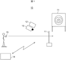
実施形態の射撃訓練システムについて図1、2を用いて説明する。図1は実施形態における射撃訓練システムの概略構成図である。図2は図1の射撃訓練システムのブロック構成図である。 The shooting training system of the embodiment will be described with reference to FIGS. 1 and 2. FIG. 1 is a schematic configuration diagram of a shooting training system according to an embodiment. FIG. 2 is a block configuration diagram of the shooting training system of FIG.
図1に示すように、射撃訓練システム10は、標的11と、標的11に映像を投影するプロジェクタ12と、標的11を撮影する赤外線カメラ13と、プロジェクタ12や赤外線カメラ13を制御する端末14と、を備える。標的11は射撃対象となり、ラバー等で構成されるスクリーンである。プロジェクタ12は標的11に射撃対象の図や映像を投影可能であって、弾丸の当たらない位置に設置される。赤外線カメラ13は標的11が撮影可能であって、弾丸の当たらない位置に設置される。射手が射座側から標的11に対して射撃を実施し、火器15から発射された弾丸が標的11に命中・貫通することで、標的11に摩擦による熱が生じ赤外線カメラ13により温度変化を検出させる。着弾結果は射手が端末14に設けられる表示装置により見ることができる。
As shown in FIG. 1, the
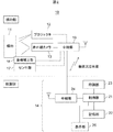
図2に示すように、プロジェクタ12は中継部16を介して端末14によって制御されるようにしてもよいし、他の装置とは独立していてもよい。赤外線カメラ13はカメラおよびレンズを有し、標的11を撮影し、撮影した映像を中継部16に伝送する。中継部16は無線又は有線を介して取得した映像を端末14へ伝送する。センサ部17は標的11側の照度、温度、風速等の環境データを取得し、端末14へ伝送されデータの補正に使用してもよいし、使用しなくてもよい。使用した場合は、着弾の精度を調整することができ、誤検知を低減することができる。座標補正部18は、標的11を撮影している赤外線カメラ13の映像の台形補正と、赤外線カメラ13が撮影した映像とプロジェクタ12の投影映像の座標を合わせるために使用される。
As shown in FIG. 2, the
端末14は、中継部24を介して無線又は有線から伝送された映像を制御部21へ伝送する。制御部21は、標的11を撮影した映像から座標を算出する。座標は、着弾地点の温度変化が発生した場所の画素から算出される。
The
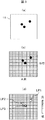
着弾検知について図3を用いて説明する。図3は着弾検知を説明する図であり、図3(a)は標的への着弾結果を示す図であり、図3(b)は赤外線カメラで撮影した画像の画素から座標を算出するイメージを示す図であり、図3(c)は赤外線カメラで撮影した温度画像を示す図である。
図3(a)に黒丸で示すように、3発の弾丸が標的11に着弾している。制御部21は画像処理により温度変化の生じた箇所の画素から着弾点を座標に変換する。ここで、図3(b)に示すように、撮影された標的11は、A列、B行で構成され、すなわち、A×Bの解像度を有する。図3(b)の黒丸は着弾画像を表している。
Landing detection will be described with reference to FIG. FIG. 3 is a diagram for explaining impact detection, FIG. 3 (a) is a diagram showing the impact result on a target, and FIG. 3 (b) is an image of calculating coordinates from pixels of an image taken by an infrared camera. 3 (c) is a diagram showing a temperature image taken by an infrared camera.
As shown by the black circles in FIG. 3A, three bullets have landed on the
また、制御部21は、標的11に投影している映像に点数があれば座標から点数計算を行い、採点を行う。端末14の記録部22にあらかじめ標的と点数テーブルを保有させておき、映像上の標的と標的に割り付けた点数テーブルから着弾点に応じて点数を算出し、得点として計算をする。点数は射撃中に計算され、合計得点を算出し、射撃結果として出力される。制御部21は射撃結果をデータとして記録部22に保存し、計算され採点された射撃結果は印刷部23で印刷したり、表示部25で表示したりする。
Further, if the image projected on the
射撃する銃の種類から連射の射撃方法がある。この場合、温度の変化によるスレッショルドを設けて連射による着弾を判断する。すなわち、標的11に着弾した弾が発生させる温度は時間とともに下がっていく。例えば、図3(c)に示すように、着弾点LP1,LP2,LP3の順に温度が高くなっており、着弾点LP1,LP2,LP3の順に着弾時期が新しくなっている。一番高温になる温度で着弾とし、連射された次の弾が着弾するまでに下がる温度より高い温度をスレッショルドとしておけば、次の弾の着弾を判別することができる。季節や射場の環境による温度変化に対応して、スレッショルドを調整することにより、誤検知を無くすことができる。
There is a continuous shooting method depending on the type of gun to shoot. In this case, a threshold due to a change in temperature is provided to determine the impact due to continuous firing. That is, the temperature generated by the bullet landing on the
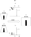
次に、座標補正部18について図4を用いて説明する。図4は標的画像の補正を説明する図であり、図4(a)は天井に赤外線カメラを取り付け場合の標的側の側面図であり、図4(b)は床面に赤外線カメラを取り付け場合の標的側の側面図であり、図4(c)は図4(a)の場合の補正前の標的映像を示す図であり、図4(d)は図4(b)の場合の補正前の標的映像を示す図であり、図4(e)は補正された標的映像を示す図である。
Next, the coordinate
標的11の持つ座標に対して、赤外線カメラ13で撮影した映像の座標を合わせるため、補正する必要がある。座標補正部18は、標的11側に熱源または近赤外LEDまたは赤外線反射材等を備え、赤外線カメラ13でとらえた熱源又は近赤外LEDまたは赤外線反射材に合わせるように画像を補正する。また、画像に合わせて座標を合わせこむ。
It is necessary to correct the coordinates of the image captured by the
また、射座側から発射される弾丸が命中しない場所に赤外線カメラ13およびプロジェクタ12を設置するという制約がある。このため図4(a)(b)に示すように、標的11と赤外線カメラ13の位置関係は標的11に対して赤外線カメラ13を天井31又は床面(地面)32に取り付け、ある程度の角度を持たせて設置する必要がある。その結果、標的映像は、図4(c)(d)に示すように、上下方向で幅が異なる台形状になり、標的11と画像の座標が異なってしまう。なお、プロジェクタ12から投影される映像も台形補正されている。また、赤外線カメラ13およびプロジェクタ12を射手が発射した実弾による直接の被弾から保護する防弾材33が設けられている。
Further, there is a restriction that the
そこで、赤外線カメラ13にレンズを取りつけ、座標補正部18における台形補正により、図4(e)に示すように、標的11と画像の座標を合わせる。また、標的11に表示させた映像と撮影された映像の座標を合わせる。
Therefore, a lens is attached to the
本実施形態は、赤外線カメラのみの簡単な構成で弾丸の着弾位置を検知することが可能である。 In this embodiment, it is possible to detect the landing position of a bullet with a simple configuration of only an infrared camera.
また、本実施形態は、プロジェクタ等で映像により標的を投影する射撃方式がある。映像を投影していても、着弾時の熱変化をとらえるため、従来の画像処理では判別の難しかった、着弾位置が映像で判別できない映像の暗い部分への着弾に対しても問題なく検知が可能となる。また、屋外の昼夜においても同様な方式で射撃訓練が可能となる。 Further, in the present embodiment, there is a shooting method in which a target is projected by an image with a projector or the like. Even if the image is projected, the heat change at the time of landing is captured, so it is possible to detect the landing on a dark part of the image where the landing position cannot be determined by the image, which was difficult to distinguish with conventional image processing. It becomes. In addition, shooting training can be performed in the same manner during the day and night outdoors.
標的は、伸び率の大きいラバーを使用することにより弾が貫通しても大きな穴が開かない。本実施形態においても、標的11にラバーを使用しているので、簡単に固定して射撃が可能であり、整備性に有利である。標的11がラバー等の材料のみとなるため、安価となる。着弾により損傷した標的11は、ラバー等の交換のみになるため、メンテナンス費用が低減できる。
By using a rubber with a high elongation rate, the target does not open a large hole even if the bullet penetrates. Also in this embodiment, since rubber is used for the
また、射撃においては、標的の後方にバックストップと呼ばれる弾丸が跳弾しないように受け止める構造物である停弾装置が設置される。本実施形態においては、温度変化が検知できる状態であれば、特に木枠等のラバーを設置する構造を持たなくても、停弾装置にラバーを張り付けて固定しても良いし、停弾装置そのものを標的として使用しても良い。 In shooting, a bullet stop device called a backstop is installed behind the target, which is a structure that catches bullets so that they do not bounce. In the present embodiment, as long as the temperature change can be detected, the rubber may be attached and fixed to the bullet stop device without having a structure for installing a rubber such as a wooden frame, or the bullet stop device may be fixed. It may be used as a target.
標的には、昇降/下降、起きれ/倒れ、回転による隠顕動作をするものがある。また、走行する標的に対して射撃訓練が可能な移動標的がある。標的が撮影可能なように赤外線カメラを取り付けることで、このような標的に対しても標的側に着弾検知のセンサとして、使用することが可能となる。 Some targets perform hidden movements by ascending / descending, getting up / falling, and rotating. In addition, there are moving targets that can be trained for shooting against moving targets. By attaching an infrared camera so that the target can be photographed, it is possible to use such a target as a sensor for landing detection on the target side.
以上、本発明者らによってなされた発明を実施形態に基づき具体的に説明したが、本発明は、上記実施形態に限定されるものではなく、種々変更可能であることはいうまでもない。 Although the inventions made by the present inventors have been specifically described above based on the embodiments, it goes without saying that the present invention is not limited to the above embodiments and can be variously modified.
例えば、実施形態では標的はスクリーンにプロジェクタで映像を投影して構成しているが、スクリーンにプロジェクタで映像を投影しないで標的を構成してもよい。 For example, in the embodiment, the target is configured by projecting an image on the screen with a projector, but the target may be configured without projecting the image on the screen by the projector.
また、赤外線カメラおよびプロジェクタを天井または床面に設置する例を説明したが、左右の壁等に設置するようにしてもよい。 Further, although the example in which the infrared camera and the projector are installed on the ceiling or the floor surface has been described, they may be installed on the left and right walls or the like.
また、赤外線カメラを標的よりも前(射座側)に設置する例を説明したが、標的よりも後に設置するようにしてもよい。 Further, although the example in which the infrared camera is installed in front of the target (shooting seat side) has been described, the infrared camera may be installed after the target.
また、赤外線カメラは弾丸が標的に命中・貫通することで標的に発生する摩擦熱を検知する例を説明したが、弾丸自体が発する熱を検知するようにしてもよい。 Further, although the infrared camera has described an example of detecting the frictional heat generated at the target when the bullet hits / penetrates the target, the heat generated by the bullet itself may be detected.
10・・・射撃訓練システム
11・・・標的
13・・・赤外線カメラ
14・・・端末
10 ...
Claims (4)
前記標的を撮影する赤外線カメラと、
前記赤外線カメラが撮影した映像を画像処理する端末と、
を備え、
前記端末は、弾丸が前記標的に着弾するときの熱を前記赤外線カメラにより検出させ、画像処理により座標として着弾位置を検出するよう構成される射撃訓練システム。 The target of live shooting composed of rubber,
An infrared camera that shoots the target and
A terminal that processes images taken by the infrared camera and
With
The terminal is a shooting training system configured to detect the heat when a bullet lands on the target by the infrared camera and detect the landing position as coordinates by image processing.
さらに、座標補正部を備え、
前記赤外線カメラは射座側から発射される弾丸が命中しない場所に設置され、
前記座標補正部は、前記赤外線カメラが設置される場所に起因する映像の歪を補正するよう構成される射撃訓練システム。 In the shooting training system of claim 1,
In addition, it is equipped with a coordinate correction unit.
The infrared camera is installed in a place where bullets fired from the shooting seat side do not hit.
The coordinate correction unit is a shooting training system configured to correct distortion of an image caused by a place where the infrared camera is installed.
前記座標補正部は、前記標的側に熱源または近赤外LEDまたは赤外線反射材を備え、前記赤外線カメラでとらえた前記熱源または前記近赤外LEDに合わせるように画像を補正し、補正した画像に合わせて座標を合わせこむよう構成される射撃訓練システム。 In the shooting training system of claim 2,
The coordinate correction unit is provided with a heat source or a near-infrared LED or an infrared reflector on the target side, and corrects the image so as to match the heat source or the near-infrared LED captured by the infrared camera, and the corrected image is obtained. A shooting training system that is configured to match the coordinates.
さらに、前記標的に映像を投影する映像投影装置を備える射撃訓練システム。 In the shooting training system of claim 3,
Further, a shooting training system including an image projection device for projecting an image on the target.
Priority Applications (1)
| Application Number | Priority Date | Filing Date | Title |
|---|---|---|---|
| JP2019149701A JP2021032425A (en) | 2019-08-19 | 2019-08-19 | Shooting training system |
Applications Claiming Priority (1)
| Application Number | Priority Date | Filing Date | Title |
|---|---|---|---|
| JP2019149701A JP2021032425A (en) | 2019-08-19 | 2019-08-19 | Shooting training system |
Publications (1)
| Publication Number | Publication Date |
|---|---|
| JP2021032425A true JP2021032425A (en) | 2021-03-01 |
Family
ID=74676411
Family Applications (1)
| Application Number | Title | Priority Date | Filing Date |
|---|---|---|---|
| JP2019149701A Pending JP2021032425A (en) | 2019-08-19 | 2019-08-19 | Shooting training system |
Country Status (1)
| Country | Link |
|---|---|
| JP (1) | JP2021032425A (en) |
Cited By (3)
| Publication number | Priority date | Publication date | Assignee | Title |
|---|---|---|---|---|
| JP2023016609A (en) * | 2021-07-21 | 2023-02-02 | 株式会社日立国際電気 | shooting training system |
| CN116026190A (en) * | 2022-12-08 | 2023-04-28 | 沈阳中科智胜科技有限公司 | Method, storage medium and equipment for fusing target report based on multiple sensors |
| JP2024021926A (en) * | 2022-08-04 | 2024-02-16 | 株式会社日立国際電気 | shooting training system |
Citations (8)
| Publication number | Priority date | Publication date | Assignee | Title |
|---|---|---|---|---|
| JPH11108596A (en) * | 1997-10-03 | 1999-04-23 | Nippon Avionics Co Ltd | Bullet hole detection device and automatic shooting system |
| JP2000146487A (en) * | 1998-11-17 | 2000-05-26 | Babcock Hitachi Kk | Shooting training apparatus |
| JP2002544471A (en) * | 1999-05-14 | 2002-12-24 | デイナミート ノーベル ゲゼルシャフト ミット ベシュレンクテル ハフツング エクスプロジーフシュトッフ− ウント ジステームテヒニク | Hit evaluation or shooting evaluation method at shooting facility and shooting facility |
| CN1536327A (en) * | 2003-05-13 | 2004-10-13 | 上海亿湾特训练设备科技有限公司 | Hitting point temperature difference location method |
| CN2716792Y (en) * | 2004-07-08 | 2005-08-10 | 上海亿湾特训练设备科技有限公司 | A novel impact point coordinate positioning device |
| US20070160960A1 (en) * | 2005-10-21 | 2007-07-12 | Laser Shot, Inc. | System and method for calculating a projectile impact coordinates |
| JP2010026870A (en) * | 2008-07-22 | 2010-02-04 | Seiko Epson Corp | Image processing apparatus, image display apparatus and image data generating method |
| JP2019082402A (en) * | 2017-10-30 | 2019-05-30 | 株式会社フジタ | State evaluation device of inspection object |
-
2019
- 2019-08-19 JP JP2019149701A patent/JP2021032425A/en active Pending
Patent Citations (8)
| Publication number | Priority date | Publication date | Assignee | Title |
|---|---|---|---|---|
| JPH11108596A (en) * | 1997-10-03 | 1999-04-23 | Nippon Avionics Co Ltd | Bullet hole detection device and automatic shooting system |
| JP2000146487A (en) * | 1998-11-17 | 2000-05-26 | Babcock Hitachi Kk | Shooting training apparatus |
| JP2002544471A (en) * | 1999-05-14 | 2002-12-24 | デイナミート ノーベル ゲゼルシャフト ミット ベシュレンクテル ハフツング エクスプロジーフシュトッフ− ウント ジステームテヒニク | Hit evaluation or shooting evaluation method at shooting facility and shooting facility |
| CN1536327A (en) * | 2003-05-13 | 2004-10-13 | 上海亿湾特训练设备科技有限公司 | Hitting point temperature difference location method |
| CN2716792Y (en) * | 2004-07-08 | 2005-08-10 | 上海亿湾特训练设备科技有限公司 | A novel impact point coordinate positioning device |
| US20070160960A1 (en) * | 2005-10-21 | 2007-07-12 | Laser Shot, Inc. | System and method for calculating a projectile impact coordinates |
| JP2010026870A (en) * | 2008-07-22 | 2010-02-04 | Seiko Epson Corp | Image processing apparatus, image display apparatus and image data generating method |
| JP2019082402A (en) * | 2017-10-30 | 2019-05-30 | 株式会社フジタ | State evaluation device of inspection object |
Cited By (5)
| Publication number | Priority date | Publication date | Assignee | Title |
|---|---|---|---|---|
| JP2023016609A (en) * | 2021-07-21 | 2023-02-02 | 株式会社日立国際電気 | shooting training system |
| JP7444819B2 (en) | 2021-07-21 | 2024-03-06 | 株式会社日立国際電気 | shooting training system |
| JP2024021926A (en) * | 2022-08-04 | 2024-02-16 | 株式会社日立国際電気 | shooting training system |
| JP7741039B2 (en) | 2022-08-04 | 2025-09-17 | 株式会社国際電気 | Shooting Training System |
| CN116026190A (en) * | 2022-12-08 | 2023-04-28 | 沈阳中科智胜科技有限公司 | Method, storage medium and equipment for fusing target report based on multiple sensors |
Similar Documents
| Publication | Publication Date | Title |
|---|---|---|
| KR101017144B1 (en) | Screen real shooting system by laser coordinate tracking | |
| US8360776B2 (en) | System and method for calculating a projectile impact coordinates | |
| US20110297742A1 (en) | Methodology for bore sight alignment and correcting ballistic aiming points using an optical (strobe) tracer | |
| US20100201620A1 (en) | Firearm training system | |
| JP2021032425A (en) | Shooting training system | |
| US6973865B1 (en) | Dynamic pointing accuracy evaluation system and method used with a gun that fires a projectile under control of an automated fire control system | |
| CA3116464A1 (en) | Device and method for shot analysis | |
| US20140335478A1 (en) | System and method for marksmanship training | |
| US20070254266A1 (en) | Marksmanship training device | |
| JP2020041743A (en) | Shooting training system | |
| JP2016166731A (en) | Shooting system, gun, and data processing device | |
| KR101314179B1 (en) | Apparatus for fire training simulation system | |
| KR101330060B1 (en) | Method and system for training full duplex simulator shooting tactics using laser | |
| AU2020225664B2 (en) | Device and method for shot analysis | |
| US20080192979A1 (en) | Shot pattern and target display | |
| US20140375562A1 (en) | System and Process for Human-Computer Interaction Using a Ballistic Projectile as an Input Indicator | |
| JP3654753B2 (en) | Bullet hole detection device and automatic shooting scoring device | |
| US20070160960A1 (en) | System and method for calculating a projectile impact coordinates | |
| JP4614783B2 (en) | Shooting training system | |
| KR102151340B1 (en) | impact point detection method of shooting system with bullet ball pellet | |
| RU88790U1 (en) | MULTIMEDIA INTERACTIVE RUNNING DASH | |
| KR101263767B1 (en) | A real shoot training system using a moving image | |
| RU2579831C1 (en) | Method of forming projection target and device therefor | |
| JP7444819B2 (en) | shooting training system | |
| KR101542926B1 (en) | Simulation of fire shooting system |
Legal Events
| Date | Code | Title | Description |
|---|---|---|---|
| A621 | Written request for application examination |
Free format text: JAPANESE INTERMEDIATE CODE: A621 Effective date: 20220322 |
|
| A977 | Report on retrieval |
Free format text: JAPANESE INTERMEDIATE CODE: A971007 Effective date: 20230117 |
|
| A131 | Notification of reasons for refusal |
Free format text: JAPANESE INTERMEDIATE CODE: A131 Effective date: 20230131 |
|
| A521 | Request for written amendment filed |
Free format text: JAPANESE INTERMEDIATE CODE: A523 Effective date: 20230322 |
|
| A131 | Notification of reasons for refusal |
Free format text: JAPANESE INTERMEDIATE CODE: A131 Effective date: 20230530 |
|
| A02 | Decision of refusal |
Free format text: JAPANESE INTERMEDIATE CODE: A02 Effective date: 20231128 |