JP2019085902A - Electric air quantity adjustment device - Google Patents
Electric air quantity adjustment device Download PDFInfo
- Publication number
- JP2019085902A JP2019085902A JP2017213239A JP2017213239A JP2019085902A JP 2019085902 A JP2019085902 A JP 2019085902A JP 2017213239 A JP2017213239 A JP 2017213239A JP 2017213239 A JP2017213239 A JP 2017213239A JP 2019085902 A JP2019085902 A JP 2019085902A
- Authority
- JP
- Japan
- Prior art keywords
- throttle
- throttle valve
- recess
- adjusting device
- drive
- Prior art date
- Legal status (The legal status is an assumption and is not a legal conclusion. Google has not performed a legal analysis and makes no representation as to the accuracy of the status listed.)
- Pending
Links
- 230000029058 respiratory gaseous exchange Effects 0.000 claims description 26
- 238000003780 insertion Methods 0.000 claims description 11
- 230000037431 insertion Effects 0.000 claims description 11
- 238000011144 upstream manufacturing Methods 0.000 claims description 6
- 238000004891 communication Methods 0.000 claims description 3
- 239000000463 material Substances 0.000 claims description 2
- 239000004576 sand Substances 0.000 description 5
- 230000007246 mechanism Effects 0.000 description 4
- 239000000428 dust Substances 0.000 description 3
- 238000004519 manufacturing process Methods 0.000 description 3
- 230000008859 change Effects 0.000 description 2
- 239000000446 fuel Substances 0.000 description 2
- 230000009467 reduction Effects 0.000 description 2
- 229910000831 Steel Inorganic materials 0.000 description 1
- 230000008901 benefit Effects 0.000 description 1
- 238000006073 displacement reaction Methods 0.000 description 1
- 230000000694 effects Effects 0.000 description 1
- 230000006872 improvement Effects 0.000 description 1
- 238000000034 method Methods 0.000 description 1
- 230000004044 response Effects 0.000 description 1
- 238000007789 sealing Methods 0.000 description 1
- 239000010959 steel Substances 0.000 description 1
- 238000005406 washing Methods 0.000 description 1
- XLYOFNOQVPJJNP-UHFFFAOYSA-N water Substances O XLYOFNOQVPJJNP-UHFFFAOYSA-N 0.000 description 1
Images




Classifications
-
- F—MECHANICAL ENGINEERING; LIGHTING; HEATING; WEAPONS; BLASTING
- F02—COMBUSTION ENGINES; HOT-GAS OR COMBUSTION-PRODUCT ENGINE PLANTS
- F02D—CONTROLLING COMBUSTION ENGINES
- F02D9/00—Controlling engines by throttling air or fuel-and-air induction conduits or exhaust conduits
- F02D9/08—Throttle valves specially adapted therefor; Arrangements of such valves in conduits
- F02D9/10—Throttle valves specially adapted therefor; Arrangements of such valves in conduits having pivotally-mounted flaps
- F02D9/1065—Mechanical control linkage between an actuator and the flap, e.g. including levers, gears, springs, clutches, limit stops of the like
-
- F—MECHANICAL ENGINEERING; LIGHTING; HEATING; WEAPONS; BLASTING
- F02—COMBUSTION ENGINES; HOT-GAS OR COMBUSTION-PRODUCT ENGINE PLANTS
- F02D—CONTROLLING COMBUSTION ENGINES
- F02D9/00—Controlling engines by throttling air or fuel-and-air induction conduits or exhaust conduits
- F02D9/02—Controlling engines by throttling air or fuel-and-air induction conduits or exhaust conduits concerning induction conduits
-
- F—MECHANICAL ENGINEERING; LIGHTING; HEATING; WEAPONS; BLASTING
- F02—COMBUSTION ENGINES; HOT-GAS OR COMBUSTION-PRODUCT ENGINE PLANTS
- F02D—CONTROLLING COMBUSTION ENGINES
- F02D9/00—Controlling engines by throttling air or fuel-and-air induction conduits or exhaust conduits
- F02D9/08—Throttle valves specially adapted therefor; Arrangements of such valves in conduits
- F02D9/10—Throttle valves specially adapted therefor; Arrangements of such valves in conduits having pivotally-mounted flaps
- F02D9/1035—Details of the valve housing
- F02D9/106—Sealing of the valve shaft in the housing, e.g. details of the bearings
Landscapes
- Engineering & Computer Science (AREA)
- Chemical & Material Sciences (AREA)
- Combustion & Propulsion (AREA)
- Mechanical Engineering (AREA)
- General Engineering & Computer Science (AREA)
- Control Of Throttle Valves Provided In The Intake System Or In The Exhaust System (AREA)
Abstract
Description
本発明は、エンジンに供給される空気量を調整する空気量調整装置に関し、特に、別体として構成した駆動部とスロットル部とを一体に接続し前記モータにより前記スロットルバルブを開閉可能とした電動式空気量調整装置に関する。 The present invention relates to an air amount adjusting device for adjusting an air amount supplied to an engine, and in particular, an electric motor which integrally connects a separate drive unit and a throttle unit so that the throttle valve can be opened and closed by the motor. Type air amount adjusting device.
従来、2輪車をはじめ汎用エンジンは排気量や気筒数などの違いからスロットルボディの取り付け方法が異なり、エンジンの数とほぼ同等のスロットルボディが存在していた。 In the past, two-wheeled vehicles and other general-purpose engines differed in the method of attaching the throttle body due to differences in displacement and the number of cylinders, and there were throttle bodies substantially equal to the number of engines.
一方、近年は排出ガスの規制強化対策や利便性の向上の要求から、スロットルバルブ開度を電子的に制御しエンジン回転速度をより細かく制御する方策がとられており、このスロットルバルブを制御する手段として、モータおよびギア類を有する駆動部と、スロットルバルブを有するスロットル部とが別体で構成され、これらを組み合わせることで精密な角度制御を可能として供給する空気量を調整してエンジン制御を行うことが例えば特表2004−510911号公報(特許文献1)などに提示されているように知られている。 On the other hand, in recent years, there have been measures to electronically control the throttle valve opening to more finely control the engine rotation speed in response to the demand for measures to strengthen regulations on exhaust gas and improvement of convenience, and this throttle valve is controlled. As a means, a drive unit having a motor and gears, and a throttle unit having a throttle valve are separately formed, and by combining these, precise angle control is possible, and the amount of air supplied is adjusted to control engine control. What is performed is known, for example, as disclosed in JP-A-2004-510911 (Patent Document 1).
この特許文献1記載の発明は、図8に示すように駆動部1aとスロットル部2aとを別体で製造した後に一体に接続することで、駆動部を多種の製品間で共用化できるとともにスロットル部の構造も簡素化できるため、設計・製造コストを低廉に出来る利点がある。
According to the invention described in
しかしながら、このように別体で製造した駆動部とスロットル部とを組み合わせる方式の場合、スロットルバルブの回転軸を駆動部に差し込んで連結する際に芯ブレを生じるおそれがあった。 However, in the case of combining the drive unit and the throttle unit separately manufactured as described above, there is a possibility that a center deviation may occur when the rotary shaft of the throttle valve is inserted into and connected to the drive unit.
また、自動車用においては、これらの構成部品は雨水や砂塵から保護すべく、密閉式のカバーで覆う必要があるが、完全密閉の場合、温度変化により内圧が変化し密閉性が甘いと雨水等を吸収することがあった。 In addition, in automotive applications, these components need to be covered with a closed cover to protect them from rainwater and sand dust, but in the case of complete sealing, the internal pressure changes due to temperature changes, and if the sealability is poor, rainwater etc. Was absorbed.
一方で、芝刈り機など野外の非舗装路で用いられる汎用エンジンは、砂塵環境で用いられること、また、高圧洗浄機による洗車が高頻度で生じることが予想され、自動車用途に比べ、カバー内部の呼吸孔からの雨水や砂塵が侵入する確率が高まることが考えられるため、防水・防塵性能が特に強く求められていた。 On the other hand, general-purpose engines used on outdoor non-paved roads, such as lawn mowers, are expected to be used in a dusty environment and to cause frequent occurrence of car washing by high-pressure washers. Since the probability that rain water and dust from the breathing hole of the body will intrude is considered to increase, waterproof and dustproof performance have been particularly strongly demanded.
本発明は、エンジンに供給される空気量を調整する空気量調整装置において、駆動部とスロットル部を別体から構成することによって部品の共通化を容易にするとともにスロットルバルブの回転軸を芯ブレが生じることなく正確に駆動部に接続することを可能とし、更に、雨水や砂塵が駆動部に浸入することを防止した電動式空気量調整装置を提供することを課題とする。 The present invention relates to an air amount adjusting device for adjusting the amount of air supplied to an engine, in which the drive portion and the throttle portion are separately provided to facilitate the sharing of parts and to make the rotational shaft of the throttle valve It is an object of the present invention to provide an electrically-operated air amount adjusting device capable of accurately connecting to a drive unit without occurrence of the above, and further preventing rainwater and sand dust from entering the drive unit.
前記課題を解決するためになされた本発明は、モータを有する駆動部と、スロットルバルブを有するスロットル部と、を別体として構成し、前記駆動部と前記スロットル部とを一体に接続して前記モータにより前記スロットルバルブを開閉可能とした、エンジンへ供給される空気流量を調整する電動式空気量調整装置であって、前記スロットルバルブの回転軸に取り付けられる軸受の外輪を前記駆動部に形成された凹部および前記スロットル部に形成された凹部の双方に挿入されるインローとして用い、前記駆動部と前記スロットル部との間で前記回転軸の同心を得ることを特徴とする。 The present invention, which has been made to solve the above problems, has a drive unit having a motor and a throttle unit having a throttle valve as separate parts, and the drive unit and the throttle unit are integrally connected to each other. An electric air amount adjusting device for adjusting the flow rate of air supplied to an engine, wherein the throttle valve can be opened and closed by a motor, wherein an outer ring of a bearing attached to a rotation shaft of the throttle valve is formed in the drive portion It is characterized in that it is used as an inlay inserted into both of the recessed portion and the recessed portion formed in the throttle portion, and the concentricity of the rotation axis is obtained between the drive portion and the throttle portion.
また、前記軸受が球軸受である場合、製作精度が高く、かつ入手の容易な軸受を使用できるため、精度面およびコスト面の両方において望ましい。 In addition, when the bearing is a ball bearing, it is desirable both in terms of accuracy and cost because bearings with high manufacturing accuracy and easy to obtain can be used.
更に、前記駆動部は下面の回転軸挿入孔を除いてシール材により前記スロットル部と密接されており、前記回転軸挿入孔は前記駆動部の前記凹部に形成された呼吸溝、前記スロットル部の前記凹部に形成された呼吸溝および前記スロットル部における前記スロットルバルブの上流位置に形成された呼吸孔と連通する場合、呼吸溝および呼吸孔によって駆動部内が大気圧とほぼ等しい気圧に保たれるため、例えば温度変化による内圧の変化を生じることなく防水・防塵効果を発揮することができる。 Furthermore, the drive unit is in close contact with the throttle unit by a seal material except for the rotation shaft insertion hole on the lower surface, and the rotation shaft insertion hole is a breathing groove formed in the recess of the drive unit; When communicating with the breathing groove formed in the recess and the breathing hole formed in the throttle unit at a position upstream of the throttle valve, the inside of the drive unit is maintained at an atmospheric pressure substantially equal to the atmospheric pressure by the breathing groove and breathing hole For example, the waterproof / dustproof effect can be exhibited without causing a change in internal pressure due to a temperature change.
本発明の電動式空気量調整装置によれば、軸受の外輪を駆動部とスロットル部の双方の凹部に挿入されるインローとして用いることで、駆動部とスロットル部の間で確実な回転軸の位置合わせをして、芯ブレの発生を防止することを可能とした。 According to the electric air amount adjusting device of the present invention, by using the outer ring of the bearing as the inlay inserted into the recess of both the drive portion and the throttle portion, the position of the rotary shaft can be assured between the drive portion and the throttle portion It was possible to prevent the occurrence of core blurring by aligning them.
更に、シールされた駆動部内に通じる呼吸溝および呼吸孔を設けたことでスロットルバルブ上流のエアクリーナとの間のクリーンかつほぼ大気圧の環境と連通していることで駆動部内がクリーンな状態かつほぼ大気圧に保たれるため、例えば温度変化による内圧の変化を生じることがなく、駆動部内に雨水や砂塵が浸入することを防止することができるとともに、呼吸溝および呼吸孔を予め内部に形成したことで、余分な配管をする必要もないことから部品数の削減及び省コスト化に貢献できる。 Furthermore, by providing a breathing groove and a vent leading to the inside of the sealed drive part, the inside of the drive part is clean and almost clean by communicating with the clean and almost atmospheric environment between the air cleaner and the throttle valve upstream. Since the atmospheric pressure is maintained, for example, changes in internal pressure due to temperature changes do not occur, and it is possible to prevent rainwater and sand from infiltrating into the drive unit, and the breathing groove and breathing hole are formed in advance. This can contribute to the reduction of the number of parts and the cost saving since there is no need to carry out extra piping.
以下に、本発明の好ましい実施の形態について図面を参照して詳細に説明する。 Hereinafter, preferred embodiments of the present invention will be described in detail with reference to the drawings.
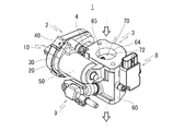
図1は本発明の電動式空気量調整装置の好ましい実施の形態を示す図であり、電動式空気量調整装置1は、ブラケット20およびカバー30をクリップ40により結合してなるハウジング10内にモータ50とギア(図示せず)とからなる減速機構および前記減速機構に接続された回転軸保持部材51を収装した駆動部2と、スロットルボディ60内に回転軸71および弁体72とからなるスロットルバルブ70を回転自在に収装したスロットル部3と、を一体に組み立ててなるものである。
FIG. 1 is a view showing a preferred embodiment of an electric air amount adjusting device according to the present invention, and the electric air amount adjusting
尚、符号91はスロットルバルブ70の開度を検知して出力するセンサー部、符号92は燃料供給部であるが、本明細書においては説明を省略する。
Reference numeral 91 denotes a sensor unit for detecting and outputting the opening degree of the
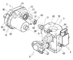
図2は本発明の好ましい実施の形態における駆動部2とスロットル部3を分離した状態を示す分解斜視図である。
FIG. 2 is an exploded perspective view showing a state in which the
駆動部2のハウジング10を構成するブラケット20は、下面に回転軸挿入孔21および前記回転軸挿入孔21と同心でより大径の凹部22を有し、上側凹部22の外周の一部に呼吸溝23が形成されている(図3参照)。
The
スロットル部3のスロットルボディ60は、上面に回転軸挿入孔61および前記回転軸挿入孔61と同心でより大径の凹部62を有し、凹部62の外周の一部に呼吸溝63が形成されている(図4参照)。
The
また、スロットルボディ60を貫通して形成された気体流路64におけるスロットルバルブ70の上流位置に、呼吸溝63と連通して形成された呼吸孔65が設けられている。
Further, a
駆動部2およびスロットル部3は、スロットルボディ60の凹部62より突出したスロットルバルブ70の回転軸71に軸受80を取り付け、ハウジング10内に収装した回転軸保持部材21へ回転軸51を差し込んで接続し、スロットルボディ60の通孔66,66を介してブラケット20のネジ穴24,24へ螺着される固定ネジ4,4により駆動部2およびスロットル部3を一体に固定するものである。
The
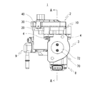
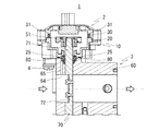
図6は図5に示したA−A線に沿って内部機構を一部省略した断面図、図7は図6の部分拡大図である。 6 is a cross-sectional view in which the internal mechanism is partially omitted along the line A-A shown in FIG. 5, and FIG. 7 is a partially enlarged view of FIG.
この図6および図7に示すように、スロットルバルブ70の回転軸71に取り付けられた軸受80の外輪81は、スロットルボディ60に形成された凹部62およびブラケット20に形成された凹部22の双方に挿入されるインローとしても用いられている。
As shown in FIGS. 6 and 7, the
そうすると、駆動部2およびスロットル部3の間で回転軸71の位置合わせを可能として回転軸71の同心を確保することができ、芯ブレの発生を防止できる。
As a result, the
尚、本実施の形態において、軸受80は鋼球を用いた球軸受を使用することで、外輪81および内輪82がともに高精度で且つ耐久性も優れた軸受を容易に入手可能となるため望ましい。
In the present embodiment, it is desirable that the
更に、ブラケット20に形成された回転軸挿入孔21、ブラケット20の凹部22に形成された呼吸溝23、スロットルボディ60の凹部62に形成された呼吸溝63およびスロットルボディ60の気体流路64に面して形成された呼吸孔65が互いに連通してシール部材25,31によりシールされた駆動部2内と気体流路64とを連通させている。
Furthermore, the rotary
このように気体流路64と駆動部2内とを連通させることで、スロットルバルブ70上流のエアクリーナ(図示せず)との間のクリーンかつほぼ大気圧の環境を通じて駆動部2内をクリーンな状態かつほぼ大気圧に保つことができる。
The communication between the
駆動部2内をクリーンな状態かつほぼ大気圧に保つことで、例えば温度変化による内圧の変化を生じることがなく、駆動部2内に雨水や砂塵が吸い込まれて浸入することを防止することができるとともに、呼吸溝23,63および呼吸孔65を予め内部に形成したことで、余分な配管をする必要もない。
By keeping the inside of the
以上のように、本発明によれば、軸受の外輪を駆動部とスロットル部の双方の凹部に挿入されるインローとして用いることで、駆動部とスロットル部の間で確実な回転軸の位置合わせをして、芯ブレの発生を防止することを可能とした。 As described above, according to the present invention, by using the outer ring of the bearing as the inlay inserted into the recess of both the drive portion and the throttle portion, reliable alignment of the rotary shaft between the drive portion and the throttle portion can be achieved. To prevent the occurrence of core blurring.
更に、シールされた駆動部内に通じる呼吸溝および呼吸孔を設けたことでスロットルバルブ上流のエアクリーナとの間のクリーンかつほぼ大気圧の環境と連通していることで駆動部内がクリーンな状態かつほぼ大気圧に保たれるため、例えば温度変化による内圧の変化を生じることがなく、駆動部内に雨水や砂塵が浸入することを防止することができるとともに、呼吸溝および呼吸孔を予め内部に形成したことで、余分な配管をする必要もないことから部品数の削減及び省コスト化に貢献できる。 Furthermore, by providing a breathing groove and a vent leading to the inside of the sealed drive part, the inside of the drive part is clean and almost clean by communicating with the clean and almost atmospheric environment between the air cleaner and the throttle valve upstream. Since the atmospheric pressure is maintained, for example, changes in internal pressure due to temperature changes do not occur, and it is possible to prevent rainwater and sand from infiltrating into the drive unit, and the breathing groove and breathing hole are formed in advance. This can contribute to the reduction of the number of parts and the cost saving since there is no need to carry out extra piping.
1 電動式空気量調整装置、2 駆動部、3 スロットル部、4 固定ネジ、8 センサー部、9 燃料供給部、10 ハウジング、20 ブラケット、21 回転軸挿入孔、22 凹部、23 呼吸溝、24 ネジ穴、25 シール部材、30 カバー、31 シール部材、40 クリップ、50 モータ、51 回転軸保持部材、60 スロットルボディ、61 回転軸挿入孔、62 凹部、63 呼吸溝、64 気体流路、65 呼吸孔、70 スロットルバルブ、71 回転軸、72 弁体、80 軸受、81 外輪、82 内輪
DESCRIPTION OF
Claims (3)
前記駆動部と前記スロットル部とを一体に接続して前記モータにより前記スロットルバルブを開閉可能とした、エンジンへ供給される空気流量を調整する電動式空気量調整装置であって、
前記スロットルバルブの回転軸に取り付けられる軸受の外輪を前記駆動部に形成された凹部および前記スロットル部に形成された凹部の双方に挿入されるインローとして用い、前記駆動部と前記スロットル部との間で前記回転軸の同心を得ることを特徴とする電動式空気量調整装置。 The drive unit having a motor and the throttle unit having a throttle valve are separately provided,
The electric air amount adjusting device according to claim 1, wherein the driving portion and the throttle portion are integrally connected so that the throttle valve can be opened and closed by the motor.
The outer ring of the bearing attached to the rotary shaft of the throttle valve is used as an inlay inserted into both the recess formed in the drive portion and the recess formed in the throttle portion, and between the drive portion and the throttle portion The motor type air amount adjusting device, wherein the concentricity of the rotating shaft is obtained by
Priority Applications (2)
| Application Number | Priority Date | Filing Date | Title |
|---|---|---|---|
| JP2017213239A JP2019085902A (en) | 2017-11-02 | 2017-11-02 | Electric air quantity adjustment device |
| US16/006,819 US20190128193A1 (en) | 2017-11-02 | 2018-06-12 | Electric air flow control device |
Applications Claiming Priority (1)
| Application Number | Priority Date | Filing Date | Title |
|---|---|---|---|
| JP2017213239A JP2019085902A (en) | 2017-11-02 | 2017-11-02 | Electric air quantity adjustment device |
Publications (1)
| Publication Number | Publication Date |
|---|---|
| JP2019085902A true JP2019085902A (en) | 2019-06-06 |
Family
ID=66243529
Family Applications (1)
| Application Number | Title | Priority Date | Filing Date |
|---|---|---|---|
| JP2017213239A Pending JP2019085902A (en) | 2017-11-02 | 2017-11-02 | Electric air quantity adjustment device |
Country Status (2)
| Country | Link |
|---|---|
| US (1) | US20190128193A1 (en) |
| JP (1) | JP2019085902A (en) |
Families Citing this family (1)
| Publication number | Priority date | Publication date | Assignee | Title |
|---|---|---|---|---|
| US11229867B2 (en) * | 2019-06-12 | 2022-01-25 | Ford Global Technologies, Llc | Air filter assembly |
Family Cites Families (23)
| Publication number | Priority date | Publication date | Assignee | Title |
|---|---|---|---|---|
| US4660996A (en) * | 1986-01-13 | 1987-04-28 | Dixon Industries Corporation | Bearing and sealing member for moveable shaft |
| US4860706A (en) * | 1987-09-14 | 1989-08-29 | Aisan Kogyo Kabushiki Kaisha | Throttle body |
| US5111775A (en) * | 1989-12-06 | 1992-05-12 | Mitsubishi Denki K.K. | Cooling water temperature controlling apparatus |
| JP2612099B2 (en) * | 1991-01-29 | 1997-05-21 | 株式会社日立製作所 | Throttle valve assembly |
| FR2694963B1 (en) * | 1992-08-21 | 1994-10-21 | Solex | Butterfly body with evolutionary intake duct and method of manufacturing such a body. |
| US5370361A (en) * | 1994-04-25 | 1994-12-06 | The Boc Group, Inc. | Butterfly valve |
| EP0714478B1 (en) * | 1994-06-18 | 2000-04-26 | AB Elektronik GmbH | Throttle valve device |
| DE29501451U1 (en) * | 1995-02-01 | 1995-06-14 | Ab Elektronik Gmbh, 59368 Werne | Throttle valve system |
| JPH10153142A (en) * | 1996-11-21 | 1998-06-09 | Aisin Seiki Co Ltd | Throttle control device |
| DE19854595A1 (en) * | 1998-11-26 | 2000-06-08 | Mannesmann Vdo Ag | Throttle valve neck |
| DE10044294A1 (en) * | 2000-09-07 | 2002-05-16 | Siemens Ag | throttle body |
| DE10048937A1 (en) * | 2000-10-04 | 2002-04-11 | Bosch Gmbh Robert | Throttle actuator |
| US6508455B2 (en) * | 2000-12-28 | 2003-01-21 | Visteon Global Technologies, Inc. | Electronic throttle body gear train module |
| JP2004339995A (en) * | 2003-05-14 | 2004-12-02 | Aisan Ind Co Ltd | Intake valve device |
| DE10341396B3 (en) * | 2003-09-05 | 2004-12-16 | Pierburg Gmbh | Flap adjustment arrangement, especially for combustion engine choke flap, has electric motor outside housing and flap support, open on one side, plugged onto contact plate protrusion via pole tube |
| US7571742B2 (en) * | 2005-03-23 | 2009-08-11 | Honeywell International Inc. | Butterfly outflow valve |
| US7694937B2 (en) * | 2006-08-09 | 2010-04-13 | Honeywell International Inc. | Outflow valve |
| DE102010006023B4 (en) * | 2010-01-27 | 2012-04-26 | Pierburg Gmbh | Sealing arrangement for a control device of an internal combustion engine |
| JP2012193847A (en) * | 2011-03-01 | 2012-10-11 | Minebea Co Ltd | Rolling bearing, throttle valve device, and abs device |
| FR2997745B1 (en) * | 2012-11-06 | 2014-11-07 | Sonceboz Automotive Sa | MOTORIZED OVERHEAD VALVE WITH IMPROVED SEALING |
| US10082092B2 (en) * | 2014-04-03 | 2018-09-25 | Ford Global Technologies, Llc | Method and system for vacuum generation using a throttle |
| US9651004B2 (en) * | 2015-05-08 | 2017-05-16 | Ford Global Technologies, Llc | Method and system for vacuum generation using a throttle comprising a hollow passage |
| IT201800003099A1 (en) * | 2018-02-27 | 2019-08-27 | Magneti Marelli Spa | THROTTLE BODY OR ACTUATOR, IN PARTICULAR FOR HIGH PRESSURE GAS SUPPLY, FITTED WITH BREATHER |
-
2017
- 2017-11-02 JP JP2017213239A patent/JP2019085902A/en active Pending
-
2018
- 2018-06-12 US US16/006,819 patent/US20190128193A1/en not_active Abandoned
Also Published As
| Publication number | Publication date |
|---|---|
| US20190128193A1 (en) | 2019-05-02 |
Similar Documents
| Publication | Publication Date | Title |
|---|---|---|
| JP5871997B2 (en) | Flap device and intake system | |
| JP4093173B2 (en) | Throttle control device for internal combustion engine | |
| US20030209682A1 (en) | Valve | |
| JP2006002601A (en) | Intake manifold and manufacturing method thereof | |
| JP4739128B2 (en) | Intake control valve | |
| JP2019085902A (en) | Electric air quantity adjustment device | |
| JP2004060525A (en) | Variable intake system | |
| JP6933066B2 (en) | Valve device | |
| JP2011169230A (en) | Compressor | |
| JP5527583B2 (en) | Intake device for internal combustion engine | |
| JP4831064B2 (en) | Throttle device for a supercharged internal combustion engine | |
| JP3838217B2 (en) | Variable intake system | |
| JP2010223128A (en) | Intake manifold pipe length switching valve actuator and pipe length switching valve actuator | |
| JP2007278123A (en) | Throttle valve control device | |
| CN104797806A (en) | Assembly structure of non-magnetic body | |
| JP3874267B2 (en) | Variable intake system | |
| JP2004339995A (en) | Intake valve device | |
| JP2017110525A (en) | Electronic throttle device for internal combustion engine | |
| JP3971619B2 (en) | Engine intake system | |
| US7296557B2 (en) | Final control element for a control unit | |
| JP2005120897A (en) | Throttle control device | |
| JP2004162680A (en) | Electric type throttle body | |
| WO2021039225A1 (en) | Valve device and method for manufacturing valve device | |
| WO2002097254A1 (en) | Engine intake device | |
| FR2955361A1 (en) | AIR SUPPLY DEVICE FOR INTERNAL COMBUSTION ENGINES |
Legal Events
| Date | Code | Title | Description |
|---|---|---|---|
| A521 | Request for written amendment filed |
Free format text: JAPANESE INTERMEDIATE CODE: A821 Effective date: 20171106 |