JP2019092265A - 電子制御装置、車載システム、および電源装置 - Google Patents
電子制御装置、車載システム、および電源装置 Download PDFInfo
- Publication number
- JP2019092265A JP2019092265A JP2017218505A JP2017218505A JP2019092265A JP 2019092265 A JP2019092265 A JP 2019092265A JP 2017218505 A JP2017218505 A JP 2017218505A JP 2017218505 A JP2017218505 A JP 2017218505A JP 2019092265 A JP2019092265 A JP 2019092265A
- Authority
- JP
- Japan
- Prior art keywords
- unit
- power supply
- control signal
- signal
- current
- Prior art date
- Legal status (The legal status is an assumption and is not a legal conclusion. Google has not performed a legal analysis and makes no representation as to the accuracy of the status listed.)
- Granted
Links
Images






Classifications
-
- H—ELECTRICITY
- H02—GENERATION; CONVERSION OR DISTRIBUTION OF ELECTRIC POWER
- H02M—APPARATUS FOR CONVERSION BETWEEN AC AND AC, BETWEEN AC AND DC, OR BETWEEN DC AND DC, AND FOR USE WITH MAINS OR SIMILAR POWER SUPPLY SYSTEMS; CONVERSION OF DC OR AC INPUT POWER INTO SURGE OUTPUT POWER; CONTROL OR REGULATION THEREOF
- H02M3/00—Conversion of DC power input into DC power output
- H02M3/02—Conversion of DC power input into DC power output without intermediate conversion into AC
- H02M3/04—Conversion of DC power input into DC power output without intermediate conversion into AC by static converters
- H02M3/10—Conversion of DC power input into DC power output without intermediate conversion into AC by static converters using discharge tubes with control electrode or semiconductor devices with control electrode
- H02M3/145—Conversion of DC power input into DC power output without intermediate conversion into AC by static converters using discharge tubes with control electrode or semiconductor devices with control electrode using devices of a triode or transistor type requiring continuous application of a control signal
- H02M3/155—Conversion of DC power input into DC power output without intermediate conversion into AC by static converters using discharge tubes with control electrode or semiconductor devices with control electrode using devices of a triode or transistor type requiring continuous application of a control signal using semiconductor devices only
- H02M3/156—Conversion of DC power input into DC power output without intermediate conversion into AC by static converters using discharge tubes with control electrode or semiconductor devices with control electrode using devices of a triode or transistor type requiring continuous application of a control signal using semiconductor devices only with automatic control of output voltage or current, e.g. switching regulators
-
- B—PERFORMING OPERATIONS; TRANSPORTING
- B60—VEHICLES IN GENERAL
- B60W—CONJOINT CONTROL OF VEHICLE SUB-UNITS OF DIFFERENT TYPE OR DIFFERENT FUNCTION; CONTROL SYSTEMS SPECIALLY ADAPTED FOR HYBRID VEHICLES; ROAD VEHICLE DRIVE CONTROL SYSTEMS FOR PURPOSES NOT RELATED TO THE CONTROL OF A PARTICULAR SUB-UNIT
- B60W60/00—Drive control systems specially adapted for autonomous road vehicles
- B60W60/001—Planning or execution of driving tasks
-
- H—ELECTRICITY
- H02—GENERATION; CONVERSION OR DISTRIBUTION OF ELECTRIC POWER
- H02M—APPARATUS FOR CONVERSION BETWEEN AC AND AC, BETWEEN AC AND DC, OR BETWEEN DC AND DC, AND FOR USE WITH MAINS OR SIMILAR POWER SUPPLY SYSTEMS; CONVERSION OF DC OR AC INPUT POWER INTO SURGE OUTPUT POWER; CONTROL OR REGULATION THEREOF
- H02M3/00—Conversion of DC power input into DC power output
- H02M3/02—Conversion of DC power input into DC power output without intermediate conversion into AC
- H02M3/04—Conversion of DC power input into DC power output without intermediate conversion into AC by static converters
- H02M3/10—Conversion of DC power input into DC power output without intermediate conversion into AC by static converters using discharge tubes with control electrode or semiconductor devices with control electrode
- H02M3/145—Conversion of DC power input into DC power output without intermediate conversion into AC by static converters using discharge tubes with control electrode or semiconductor devices with control electrode using devices of a triode or transistor type requiring continuous application of a control signal
- H02M3/155—Conversion of DC power input into DC power output without intermediate conversion into AC by static converters using discharge tubes with control electrode or semiconductor devices with control electrode using devices of a triode or transistor type requiring continuous application of a control signal using semiconductor devices only
- H02M3/156—Conversion of DC power input into DC power output without intermediate conversion into AC by static converters using discharge tubes with control electrode or semiconductor devices with control electrode using devices of a triode or transistor type requiring continuous application of a control signal using semiconductor devices only with automatic control of output voltage or current, e.g. switching regulators
- H02M3/157—Conversion of DC power input into DC power output without intermediate conversion into AC by static converters using discharge tubes with control electrode or semiconductor devices with control electrode using devices of a triode or transistor type requiring continuous application of a control signal using semiconductor devices only with automatic control of output voltage or current, e.g. switching regulators with digital control
-
- H—ELECTRICITY
- H02—GENERATION; CONVERSION OR DISTRIBUTION OF ELECTRIC POWER
- H02M—APPARATUS FOR CONVERSION BETWEEN AC AND AC, BETWEEN AC AND DC, OR BETWEEN DC AND DC, AND FOR USE WITH MAINS OR SIMILAR POWER SUPPLY SYSTEMS; CONVERSION OF DC OR AC INPUT POWER INTO SURGE OUTPUT POWER; CONTROL OR REGULATION THEREOF
- H02M3/00—Conversion of DC power input into DC power output
- H02M3/02—Conversion of DC power input into DC power output without intermediate conversion into AC
- H02M3/04—Conversion of DC power input into DC power output without intermediate conversion into AC by static converters
- H02M3/10—Conversion of DC power input into DC power output without intermediate conversion into AC by static converters using discharge tubes with control electrode or semiconductor devices with control electrode
- H02M3/145—Conversion of DC power input into DC power output without intermediate conversion into AC by static converters using discharge tubes with control electrode or semiconductor devices with control electrode using devices of a triode or transistor type requiring continuous application of a control signal
- H02M3/155—Conversion of DC power input into DC power output without intermediate conversion into AC by static converters using discharge tubes with control electrode or semiconductor devices with control electrode using devices of a triode or transistor type requiring continuous application of a control signal using semiconductor devices only
- H02M3/156—Conversion of DC power input into DC power output without intermediate conversion into AC by static converters using discharge tubes with control electrode or semiconductor devices with control electrode using devices of a triode or transistor type requiring continuous application of a control signal using semiconductor devices only with automatic control of output voltage or current, e.g. switching regulators
- H02M3/158—Conversion of DC power input into DC power output without intermediate conversion into AC by static converters using discharge tubes with control electrode or semiconductor devices with control electrode using devices of a triode or transistor type requiring continuous application of a control signal using semiconductor devices only with automatic control of output voltage or current, e.g. switching regulators including plural semiconductor devices as final control devices for a single load
-
- H—ELECTRICITY
- H02—GENERATION; CONVERSION OR DISTRIBUTION OF ELECTRIC POWER
- H02M—APPARATUS FOR CONVERSION BETWEEN AC AND AC, BETWEEN AC AND DC, OR BETWEEN DC AND DC, AND FOR USE WITH MAINS OR SIMILAR POWER SUPPLY SYSTEMS; CONVERSION OF DC OR AC INPUT POWER INTO SURGE OUTPUT POWER; CONTROL OR REGULATION THEREOF
- H02M3/00—Conversion of DC power input into DC power output
- H02M3/02—Conversion of DC power input into DC power output without intermediate conversion into AC
- H02M3/04—Conversion of DC power input into DC power output without intermediate conversion into AC by static converters
- H02M3/10—Conversion of DC power input into DC power output without intermediate conversion into AC by static converters using discharge tubes with control electrode or semiconductor devices with control electrode
- H02M3/145—Conversion of DC power input into DC power output without intermediate conversion into AC by static converters using discharge tubes with control electrode or semiconductor devices with control electrode using devices of a triode or transistor type requiring continuous application of a control signal
- H02M3/155—Conversion of DC power input into DC power output without intermediate conversion into AC by static converters using discharge tubes with control electrode or semiconductor devices with control electrode using devices of a triode or transistor type requiring continuous application of a control signal using semiconductor devices only
- H02M3/156—Conversion of DC power input into DC power output without intermediate conversion into AC by static converters using discharge tubes with control electrode or semiconductor devices with control electrode using devices of a triode or transistor type requiring continuous application of a control signal using semiconductor devices only with automatic control of output voltage or current, e.g. switching regulators
- H02M3/158—Conversion of DC power input into DC power output without intermediate conversion into AC by static converters using discharge tubes with control electrode or semiconductor devices with control electrode using devices of a triode or transistor type requiring continuous application of a control signal using semiconductor devices only with automatic control of output voltage or current, e.g. switching regulators including plural semiconductor devices as final control devices for a single load
- H02M3/1584—Conversion of DC power input into DC power output without intermediate conversion into AC by static converters using discharge tubes with control electrode or semiconductor devices with control electrode using devices of a triode or transistor type requiring continuous application of a control signal using semiconductor devices only with automatic control of output voltage or current, e.g. switching regulators including plural semiconductor devices as final control devices for a single load with a plurality of power processing stages connected in parallel
-
- B—PERFORMING OPERATIONS; TRANSPORTING
- B60—VEHICLES IN GENERAL
- B60R—VEHICLES, VEHICLE FITTINGS, OR VEHICLE PARTS, NOT OTHERWISE PROVIDED FOR
- B60R16/00—Electric or fluid circuits specially adapted for vehicles and not otherwise provided for; Arrangement of elements of electric or fluid circuits specially adapted for vehicles and not otherwise provided for
- B60R16/02—Electric or fluid circuits specially adapted for vehicles and not otherwise provided for; Arrangement of elements of electric or fluid circuits specially adapted for vehicles and not otherwise provided for electric constitutive elements
- B60R16/03—Electric or fluid circuits specially adapted for vehicles and not otherwise provided for; Arrangement of elements of electric or fluid circuits specially adapted for vehicles and not otherwise provided for electric constitutive elements for supply of electrical power to vehicle subsystems or for
-
- H—ELECTRICITY
- H02—GENERATION; CONVERSION OR DISTRIBUTION OF ELECTRIC POWER
- H02M—APPARATUS FOR CONVERSION BETWEEN AC AND AC, BETWEEN AC AND DC, OR BETWEEN DC AND DC, AND FOR USE WITH MAINS OR SIMILAR POWER SUPPLY SYSTEMS; CONVERSION OF DC OR AC INPUT POWER INTO SURGE OUTPUT POWER; CONTROL OR REGULATION THEREOF
- H02M1/00—Details of apparatus for conversion
- H02M1/0067—Converter structures employing plural converter units, other than for parallel operation of the units on a single load
- H02M1/008—Plural converter units for generating at two or more independent and non-parallel outputs, e.g. systems with plural point of load switching regulators
Landscapes
- Engineering & Computer Science (AREA)
- Power Engineering (AREA)
- Mechanical Engineering (AREA)
- Automation & Control Theory (AREA)
- Human Computer Interaction (AREA)
- Transportation (AREA)
- Dc-Dc Converters (AREA)
Abstract
【解決手段】自律走行制御ECUが有する電源回路210において、スイッチング回路22は、制御信号Cに基づいて、複数の論理回路に供給する電源をそれぞれ生成する。遷移管理部25は、スイッチング回路22を制御する。クロック生成部26は、複数のクロック信号を生成する。遷移管理部25は、制御信号生成部および複数の遅延部を有する。制御信号生成部は、クロック生成部26が生成するクロック信号から中間制御信号を生成する。遅延部は、指令信号に基づいて中間制御信号を遅延させて制御信号Cとして出力する。クロック生成部が生成するクロック信号は、少なくとも1つのクロック信号が異なる周波数である。
【選択図】図3
Description
〈車載システムの構成例〉
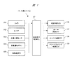
図1は、本実施の形態1による車載システム10の構成の一例を示すブロック図である。
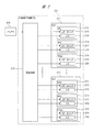
図2は、図1の車載システム10が有する自律走行制御ECU201における構成の一例を示すブロック図である。
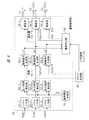
図3は、図2の自律走行制御ECU201が有する電源回路210における構成の一例を示す説明図である。

図4は、図3のスイッチング回路22における回路の一例を示す説明図である。図5は、図4のスイッチング回路22の他の回路例を示す説明図である。
図6は、図3の電源回路210が有する遷移管理部25における一例を示すブロック図である。
図7は、図6の遷移管理部25が実行する遷移判定処理の一例を示すフローチャートである。
図8は、図3の電源回路210が有する管理データベース27におけるデータ構成の一例を示す説明図である。
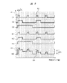
続いて、図9および図10を用いて効果を説明する。
前記実施の形態1では、遷移管理部25が制御信号の遅延を動的に制御して、伝導ノイズを低減させていたが、本実施の形態2においては、静的な制御をする技術について説明する。
図11は、本実施の形態2による遷移管理部25における構成の一例を示す説明図である。
前記実施の形態1では、スイッチング回路22の入力電流Iinを中間制御信号C’から推定する構成としていたが、本実施の形態3においては、入力電流Iinを直接計測して、高精度に伝導ノイズをコントロールする技術について説明する。
以下、図12および図13を用いて、前記実施の形態1と異なる電源回路および遷移管理部を中心に説明する。
図13は、図12の電源回路210が有する遷移管理部25における構成の一例を示す説明図である。
21 負荷
22 スイッチング回路
23 コイル
24 コンデンサ
25 遷移管理部
26 クロック生成部
27 管理データベース
28 電流センサ
41 スイッチ
42 ダイオード
43 スイッチ
51 レベルシフト部
52 出力誤差検出部
53 制御信号生成部
54 遅延部
55 基準電圧生成部
56 遷移判定部
101 カメラ
102 レーダ
103 自車位置センサ
104 自動運転ボタン
105 無線通信部
106 補助制御ECU
107 ブレーキ制御ECU
108 エンジン制御ECU
109 パワーステアリング制御ECU
201 自律走行制御ECU
210 電源回路
215 コアロジック
216 入出力回路
217 コアロジック
218 入出力回路
219 コアロジック
220 入出力回路
300 バッテリ
Claims (15)
- 複数の論理回路および複数の前記論理回路に電源を供給する電源装置を備える電子制御装置であって、
前記電源装置は、
スイッチング信号に基づいて、複数の前記論理回路に供給する電源をそれぞれ生成して出力する複数のスイッチング回路と、
複数の前記スイッチング回路を制御する遷移管理部と、
複数のクロック信号を生成するクロック生成部と、
を有し、
前記遷移管理部は、
前記クロック生成部が生成する前記クロック信号から中間制御信号を生成する制御信号生成部と、
複数の前記スイッチング回路に対応してそれぞれ設けられ、指令信号に基づいて、前記中間制御信号を遅延させ、遅延させた前記中間制御信号を前記スイッチング信号として出力する複数の遅延部と、
を有し、
前記クロック生成部が生成する複数の前記クロック信号は、少なくとも1つのクロック信号が異なる周波数である、電子制御装置。 - 請求項1記載の電子制御装置において、
前記遷移管理部は、予め設定される制御情報に基づいて、前記指令信号を生成する遷移判定部を有し、
前記遷移判定部は、前記指令信号により、複数の前記スイッチング回路の入力電流の変化量の合計値を算出して、算出した前記合計値と予め設定された電流変動しきい値とを比較して、比較した前記合計値が前記電流変動しきい値以下となるように前記遅延部の遅延量を制御する、電子制御装置。 - 請求項2記載の電子制御装置において、
前記遷移判定部は、前記制御信号生成部が生成する前記中間制御信号から複数の前記スイッチング回路の入力電流の変化量の合計値を算出する、電子制御装置。 - 請求項2記載の電子制御装置において、
前記電源装置は、複数の前記スイッチング回路に入力される入力電流を計測する電流計測部を有し、
前記遷移判定部は、前記電流計測部が計測した電流の計測結果から前記入力電流の変化量の合計値を算出する、電子制御装置。 - 請求項2記載の電子制御装置において、
前記遷移判定部は、計測タイミング信号に同期して、前記入力電流の立ち上り/立ち下りの有無を判定し、その判定結果から前記入力電流の変化量の合計値を算出する、電子制御装置。 - 請求項2記載の電子制御装置において、
前記遷移判定部が比較する前記電流変動しきい値は、前記電子制御装置の動作モード毎に異なる値である、電子制御装置。 - 請求項2記載の車載システムにおいて、
前記電源装置は、前記制御情報を格納する管理データベースを有し、
前記管理データベースは、前記入力電流を演算する際に用いる電流係数、複数の前記スイッチング回路にそれぞれ対応する遅延量、または遅延させる複数の前記スイッチング回路の優先順位の少なくともいずれか1つを格納し、
前記管理データベースに格納される前記電流係数、前記遅延量、または前記優先順位は、前記電子制御装置の動作モード毎にそれぞれ設定されている、電子制御装置。 - 請求項2記載の電子制御装置において、
前記遷移管理部は、複数の前記スイッチング回路が生成する出力電圧の誤差をそれぞれ検出して、その検出結果に基づいて、前記出力電圧の誤差を減少させるように前記中間制御信号を補正する出力電圧補正部を有する、電子制御装置。 - 車両の自律走行を制御する自律走行制御装置を具備する車載システムであって、
前記自律走行制御装置は、
複数の論理回路と、
複数の前記論理回路に電源を供給する電源装置と、
を備え、
前記電源装置は、
スイッチング信号に基づいて、複数の前記論理回路に供給する電源をそれぞれ生成して出力する複数のスイッチング回路と、
複数の前記スイッチング回路を制御する遷移管理部と、
複数のクロック信号を生成するクロック生成部と、
を有し、
前記遷移管理部は、
前記クロック生成部が生成する前記クロック信号から中間制御信号を生成する制御信号生成部と、
複数の前記スイッチング回路に対応してそれぞれ設けられ、指令信号に基づいて、前記中間制御信号を遅延させ、遅延させた前記中間制御信号を前記スイッチング信号として出力する複数の遅延部と、
を有し、
前記クロック生成部が生成する複数の前記クロック信号は、少なくとも1つのクロック信号が異なる周波数である、車載システム。 - 請求項9記載の車載システムにおいて、
前記遷移管理部は、予め設定される制御情報に基づいて、前記指令信号を生成する遷移判定部を有し、
前記遷移判定部は、前記指令信号により、複数の前記スイッチング回路の入力電流の変化量の合計値を算出して、算出した前記合計値と予め設定された電流変動しきい値とを比較して、比較した前記合計値が前記電流変動しきい値以下となるように前記遅延部の遅延量を制御する、車載システム。 - 請求項10記載の車載システムにおいて、
前記遷移判定部は、前記制御信号生成部が生成する前記中間制御信号から複数の前記スイッチング回路の入力電流の変化量の合計値を算出する、車載システム。 - 請求項10記載の車載システムにおいて、
前記電源装置は、複数の前記スイッチング回路の流れる入力電流を計測する電流計測部を有し、
前記遷移判定部は、前記電流計測部が計測した電流の計測結果から前記入力電流の変化量の合計値を算出する、車載システム。 - 請求項10記載の車載システムにおいて、
前記遷移判定部が比較する前記電流変動しきい値は、前記自律走行制御装置の動作モード毎に異なる値である、車載システム。 - スイッチング信号に基づいて、複数の論理回路に供給する電源をそれぞれ生成して出力する複数のスイッチング回路と、
複数の前記スイッチング回路を制御する遷移管理部と、
複数のクロック信号を生成するクロック生成部と、
を有し、
前記遷移管理部は、
前記クロック生成部が生成する前記クロック信号から中間制御信号を生成する制御信号生成部と、
複数の前記スイッチング回路に対応してそれぞれ設けられ、指令信号に基づいて、前記中間制御信号を遅延させ、遅延させた前記中間制御信号を前記スイッチング信号として出力する複数の遅延部と、
を有し、
前記クロック生成部が生成する複数の前記クロック信号は、少なくとも1つのクロック信号が異なる周波数である、電源装置。 - 請求項14記載の電源装置において、
前記遷移管理部は、予め設定される制御情報に基づいて前記指令信号を生成する遷移判定部を有し、
前記遷移判定部は、前記指令信号により、複数の前記スイッチング回路の入力電流の変化量の合計値を算出して、算出した前記合計値と予め設定された電流変動しきい値とを比較して、比較した前記合計値が前記電流変動しきい値以下となるように前記遅延部の遅延量を制御する、電源装置。
Priority Applications (4)
| Application Number | Priority Date | Filing Date | Title |
|---|---|---|---|
| JP2017218505A JP7004547B2 (ja) | 2017-11-13 | 2017-11-13 | 電子制御装置、車載システム、および電源装置 |
| DE112018004580.3T DE112018004580T5 (de) | 2017-11-13 | 2018-09-13 | Elektronisches steuergerät, bordsystem und stromversorgungsgerät |
| US16/760,136 US10938305B2 (en) | 2017-11-13 | 2018-09-13 | Electronic control device, in-vehicle system, and power supply device |
| PCT/JP2018/033927 WO2019092982A1 (ja) | 2017-11-13 | 2018-09-13 | 電子制御装置、車載システム、および電源装置 |
Applications Claiming Priority (1)
| Application Number | Priority Date | Filing Date | Title |
|---|---|---|---|
| JP2017218505A JP7004547B2 (ja) | 2017-11-13 | 2017-11-13 | 電子制御装置、車載システム、および電源装置 |
Publications (2)
| Publication Number | Publication Date |
|---|---|
| JP2019092265A true JP2019092265A (ja) | 2019-06-13 |
| JP7004547B2 JP7004547B2 (ja) | 2022-01-21 |
Family
ID=66437732
Family Applications (1)
| Application Number | Title | Priority Date | Filing Date |
|---|---|---|---|
| JP2017218505A Active JP7004547B2 (ja) | 2017-11-13 | 2017-11-13 | 電子制御装置、車載システム、および電源装置 |
Country Status (4)
| Country | Link |
|---|---|
| US (1) | US10938305B2 (ja) |
| JP (1) | JP7004547B2 (ja) |
| DE (1) | DE112018004580T5 (ja) |
| WO (1) | WO2019092982A1 (ja) |
Families Citing this family (5)
| Publication number | Priority date | Publication date | Assignee | Title |
|---|---|---|---|---|
| US11435438B2 (en) * | 2019-12-30 | 2022-09-06 | Woven Planet North America, Inc. | Dynamic sparse radar array for scenarios |
| CN112653116B (zh) * | 2020-12-18 | 2022-11-01 | 中国科学院国家空间科学中心 | 一种面向低母线电压的低emi星载二次电源系统 |
| US12273075B2 (en) | 2021-07-01 | 2025-04-08 | Epirus, Inc. | Systems and methods for power distribution for amplifier arrays |
| CN113783651B (zh) * | 2021-09-10 | 2024-02-06 | 阿波罗智能技术(北京)有限公司 | 平行驾驶的远程控制方法、装置、云端、车端及平行驾驶系统 |
| CN117922461A (zh) * | 2022-10-14 | 2024-04-26 | 神基科技股份有限公司 | 车辆电源供应回路监控系统及车辆电源供应回路监控方法 |
Citations (5)
| Publication number | Priority date | Publication date | Assignee | Title |
|---|---|---|---|---|
| JPS63245254A (ja) * | 1987-03-30 | 1988-10-12 | Toshiba Corp | スイツチングレギユレ−タ |
| JP2003259634A (ja) * | 2002-03-01 | 2003-09-12 | Auto Network Gijutsu Kenkyusho:Kk | 負荷駆動回路及び負荷駆動方法 |
| WO2015136746A1 (ja) * | 2014-03-12 | 2015-09-17 | 日本電気株式会社 | 電源装置及び電源装置の動作方法 |
| WO2016080452A1 (ja) * | 2014-11-19 | 2016-05-26 | エイディシーテクノロジー株式会社 | 自動運転制御装置 |
| JP2017153218A (ja) * | 2016-02-23 | 2017-08-31 | 富士通株式会社 | 電源装置 |
Family Cites Families (4)
| Publication number | Priority date | Publication date | Assignee | Title |
|---|---|---|---|---|
| JP5897642B2 (ja) * | 2014-05-30 | 2016-03-30 | ファナック株式会社 | Dc/dcコンバータ |
| JP5911030B2 (ja) | 2014-09-03 | 2016-04-27 | 三菱電機株式会社 | デジタル制御電源装置 |
| CN108141130A (zh) * | 2015-09-15 | 2018-06-08 | 日本电气株式会社 | 切换电源设备、切换电源的驱动方法和切换电源的驱动程序 |
| CN106533136B (zh) * | 2016-12-19 | 2019-03-22 | 成都芯源系统有限公司 | 多通道开关电源及其控制器和控制方法 |
-
2017
- 2017-11-13 JP JP2017218505A patent/JP7004547B2/ja active Active
-
2018
- 2018-09-13 WO PCT/JP2018/033927 patent/WO2019092982A1/ja not_active Ceased
- 2018-09-13 DE DE112018004580.3T patent/DE112018004580T5/de active Granted
- 2018-09-13 US US16/760,136 patent/US10938305B2/en active Active
Patent Citations (5)
| Publication number | Priority date | Publication date | Assignee | Title |
|---|---|---|---|---|
| JPS63245254A (ja) * | 1987-03-30 | 1988-10-12 | Toshiba Corp | スイツチングレギユレ−タ |
| JP2003259634A (ja) * | 2002-03-01 | 2003-09-12 | Auto Network Gijutsu Kenkyusho:Kk | 負荷駆動回路及び負荷駆動方法 |
| WO2015136746A1 (ja) * | 2014-03-12 | 2015-09-17 | 日本電気株式会社 | 電源装置及び電源装置の動作方法 |
| WO2016080452A1 (ja) * | 2014-11-19 | 2016-05-26 | エイディシーテクノロジー株式会社 | 自動運転制御装置 |
| JP2017153218A (ja) * | 2016-02-23 | 2017-08-31 | 富士通株式会社 | 電源装置 |
Also Published As
| Publication number | Publication date |
|---|---|
| US20200254947A1 (en) | 2020-08-13 |
| JP7004547B2 (ja) | 2022-01-21 |
| US10938305B2 (en) | 2021-03-02 |
| WO2019092982A1 (ja) | 2019-05-16 |
| DE112018004580T5 (de) | 2020-11-12 |
Similar Documents
| Publication | Publication Date | Title |
|---|---|---|
| US10938305B2 (en) | Electronic control device, in-vehicle system, and power supply device | |
| KR101423871B1 (ko) | 시험장치 | |
| US8836305B2 (en) | DC/DC converter | |
| CN106716173B (zh) | 用于运行机动车中多个雷达传感器的方法和机动车 | |
| US7791324B2 (en) | Switching regulator without a dedicated input current sense element | |
| US8698469B1 (en) | System and method for predicting output voltage ripple and controlling a switched-mode power supply | |
| KR101710252B1 (ko) | 자동차를 구동하기 위한 전기 에너지 저장 시스템을 테스트하기 위한 방법 및 장치 | |
| CN102684475B (zh) | Dc/dc降压转换器中用于负载电流的前馈控制的系统和方法 | |
| US20130049686A1 (en) | Control circuit for limiting a load current, charging circuit and motor vehicle | |
| US10132843B2 (en) | Detector and a voltage converter | |
| US20120113701A1 (en) | Inverter current measurement using a shunt resistor | |
| US20130285627A1 (en) | Apparatus and method for controlling a plurality of power converting modules and apparatus and method for analyzing power quantity imbalance | |
| US9829944B2 (en) | Multiphase voltage regulator using coupled inductors | |
| US9467058B2 (en) | Method and apparatus for controlling output voltage of DC-DC converter | |
| CN113614550B (zh) | 用于分析耗电器中的电流的设备和具有这种设备的耗电器 | |
| US9667135B2 (en) | Multiphase DC voltage converter and method for controlling a multiphase DC voltage converter | |
| US9401641B2 (en) | Systems and methods for self-calibration of a voltage regulator | |
| US20190308637A1 (en) | Electronic control device, in-vehicle system, and power supply control method | |
| US20200348740A1 (en) | Smart controller with phantom inductor current sensing for switched mode power supplies | |
| US20140269831A1 (en) | Power device temperature monitor | |
| CN109213297B (zh) | 半导体装置以及半导体装置的控制方法 | |
| CN119137837A (zh) | 外来对象检测和相关装置、方法及系统 | |
| WO2018230149A1 (ja) | 電子制御装置、車載システム、および電源装置 | |
| US20240372479A1 (en) | Dc-to-dc converters | |
| US10908205B2 (en) | Method and a device for determining a switching current of a converter of a system for inductive power transfer and a method of control |
Legal Events
| Date | Code | Title | Description |
|---|---|---|---|
| A621 | Written request for application examination |
Free format text: JAPANESE INTERMEDIATE CODE: A621 Effective date: 20200312 |
|
| A131 | Notification of reasons for refusal |
Free format text: JAPANESE INTERMEDIATE CODE: A131 Effective date: 20210601 |
|
| A521 | Request for written amendment filed |
Free format text: JAPANESE INTERMEDIATE CODE: A523 Effective date: 20210802 |
|
| A131 | Notification of reasons for refusal |
Free format text: JAPANESE INTERMEDIATE CODE: A131 Effective date: 20211102 |
|
| A521 | Request for written amendment filed |
Free format text: JAPANESE INTERMEDIATE CODE: A523 Effective date: 20211209 |
|
| TRDD | Decision of grant or rejection written | ||
| A01 | Written decision to grant a patent or to grant a registration (utility model) |
Free format text: JAPANESE INTERMEDIATE CODE: A01 Effective date: 20211221 |
|
| A61 | First payment of annual fees (during grant procedure) |
Free format text: JAPANESE INTERMEDIATE CODE: A61 Effective date: 20220104 |
|
| R150 | Certificate of patent or registration of utility model |
Ref document number: 7004547 Country of ref document: JP Free format text: JAPANESE INTERMEDIATE CODE: R150 |
|
| R250 | Receipt of annual fees |
Free format text: JAPANESE INTERMEDIATE CODE: R250 |
|
| R250 | Receipt of annual fees |
Free format text: JAPANESE INTERMEDIATE CODE: R250 |