JP2019096572A - 端子付き電線の製造方法および端子付き電線 - Google Patents
端子付き電線の製造方法および端子付き電線 Download PDFInfo
- Publication number
- JP2019096572A JP2019096572A JP2017227445A JP2017227445A JP2019096572A JP 2019096572 A JP2019096572 A JP 2019096572A JP 2017227445 A JP2017227445 A JP 2017227445A JP 2017227445 A JP2017227445 A JP 2017227445A JP 2019096572 A JP2019096572 A JP 2019096572A
- Authority
- JP
- Japan
- Prior art keywords
- terminal
- wire
- electric wire
- bonding
- conductor
- Prior art date
- Legal status (The legal status is an assumption and is not a legal conclusion. Google has not performed a legal analysis and makes no representation as to the accuracy of the status listed.)
- Granted
Links
Images









Classifications
-
- H—ELECTRICITY
- H01—ELECTRIC ELEMENTS
- H01R—ELECTRICALLY-CONDUCTIVE CONNECTIONS; STRUCTURAL ASSOCIATIONS OF A PLURALITY OF MUTUALLY-INSULATED ELECTRICAL CONNECTING ELEMENTS; COUPLING DEVICES; CURRENT COLLECTORS
- H01R43/00—Apparatus or processes specially adapted for manufacturing, assembling, maintaining, or repairing of line connectors or current collectors or for joining electric conductors
- H01R43/28—Apparatus or processes specially adapted for manufacturing, assembling, maintaining, or repairing of line connectors or current collectors or for joining electric conductors for wire processing before connecting to contact members, not provided for in groups H01R43/02 - H01R43/26
-
- B—PERFORMING OPERATIONS; TRANSPORTING
- B23—MACHINE TOOLS; METAL-WORKING NOT OTHERWISE PROVIDED FOR
- B23K—SOLDERING OR UNSOLDERING; WELDING; CLADDING OR PLATING BY SOLDERING OR WELDING; CUTTING BY APPLYING HEAT LOCALLY, e.g. FLAME CUTTING; WORKING BY LASER BEAM
- B23K20/00—Non-electric welding by applying impact or other pressure, with or without the application of heat, e.g. cladding or plating
- B23K20/002—Non-electric welding by applying impact or other pressure, with or without the application of heat, e.g. cladding or plating specially adapted for particular articles or work
- B23K20/004—Wire welding
-
- H—ELECTRICITY
- H01—ELECTRIC ELEMENTS
- H01R—ELECTRICALLY-CONDUCTIVE CONNECTIONS; STRUCTURAL ASSOCIATIONS OF A PLURALITY OF MUTUALLY-INSULATED ELECTRICAL CONNECTING ELEMENTS; COUPLING DEVICES; CURRENT COLLECTORS
- H01R11/00—Individual connecting elements providing two or more spaced connecting locations for conductive members which are, or may be, thereby interconnected, e.g. end pieces for wires or cables supported by the wire or cable and having means for facilitating electrical connection to some other wire, terminal, or conductive member, blocks of binding posts
- H01R11/11—End pieces or tapping pieces for wires, supported by the wire and for facilitating electrical connection to some other wire, terminal or conductive member
-
- H—ELECTRICITY
- H01—ELECTRIC ELEMENTS
- H01R—ELECTRICALLY-CONDUCTIVE CONNECTIONS; STRUCTURAL ASSOCIATIONS OF A PLURALITY OF MUTUALLY-INSULATED ELECTRICAL CONNECTING ELEMENTS; COUPLING DEVICES; CURRENT COLLECTORS
- H01R4/00—Electrically-conductive connections between two or more conductive members in direct contact, i.e. touching one another; Means for effecting or maintaining such contact; Electrically-conductive connections having two or more spaced connecting locations for conductors and using contact members penetrating insulation
- H01R4/10—Electrically-conductive connections between two or more conductive members in direct contact, i.e. touching one another; Means for effecting or maintaining such contact; Electrically-conductive connections having two or more spaced connecting locations for conductors and using contact members penetrating insulation effected solely by twisting, wrapping, bending, crimping, or other permanent deformation
- H01R4/18—Electrically-conductive connections between two or more conductive members in direct contact, i.e. touching one another; Means for effecting or maintaining such contact; Electrically-conductive connections having two or more spaced connecting locations for conductors and using contact members penetrating insulation effected solely by twisting, wrapping, bending, crimping, or other permanent deformation by crimping
-
- H—ELECTRICITY
- H01—ELECTRIC ELEMENTS
- H01R—ELECTRICALLY-CONDUCTIVE CONNECTIONS; STRUCTURAL ASSOCIATIONS OF A PLURALITY OF MUTUALLY-INSULATED ELECTRICAL CONNECTING ELEMENTS; COUPLING DEVICES; CURRENT COLLECTORS
- H01R43/00—Apparatus or processes specially adapted for manufacturing, assembling, maintaining, or repairing of line connectors or current collectors or for joining electric conductors
- H01R43/04—Apparatus or processes specially adapted for manufacturing, assembling, maintaining, or repairing of line connectors or current collectors or for joining electric conductors for forming connections by deformation, e.g. crimping tool
- H01R43/048—Crimping apparatus or processes
-
- H—ELECTRICITY
- H01—ELECTRIC ELEMENTS
- H01R—ELECTRICALLY-CONDUCTIVE CONNECTIONS; STRUCTURAL ASSOCIATIONS OF A PLURALITY OF MUTUALLY-INSULATED ELECTRICAL CONNECTING ELEMENTS; COUPLING DEVICES; CURRENT COLLECTORS
- H01R43/00—Apparatus or processes specially adapted for manufacturing, assembling, maintaining, or repairing of line connectors or current collectors or for joining electric conductors
- H01R43/04—Apparatus or processes specially adapted for manufacturing, assembling, maintaining, or repairing of line connectors or current collectors or for joining electric conductors for forming connections by deformation, e.g. crimping tool
- H01R43/058—Crimping mandrels
-
- B—PERFORMING OPERATIONS; TRANSPORTING
- B23—MACHINE TOOLS; METAL-WORKING NOT OTHERWISE PROVIDED FOR
- B23K—SOLDERING OR UNSOLDERING; WELDING; CLADDING OR PLATING BY SOLDERING OR WELDING; CUTTING BY APPLYING HEAT LOCALLY, e.g. FLAME CUTTING; WORKING BY LASER BEAM
- B23K20/00—Non-electric welding by applying impact or other pressure, with or without the application of heat, e.g. cladding or plating
- B23K20/10—Non-electric welding by applying impact or other pressure, with or without the application of heat, e.g. cladding or plating making use of vibrations, e.g. ultrasonic welding
-
- B—PERFORMING OPERATIONS; TRANSPORTING
- B23—MACHINE TOOLS; METAL-WORKING NOT OTHERWISE PROVIDED FOR
- B23K—SOLDERING OR UNSOLDERING; WELDING; CLADDING OR PLATING BY SOLDERING OR WELDING; CUTTING BY APPLYING HEAT LOCALLY, e.g. FLAME CUTTING; WORKING BY LASER BEAM
- B23K2101/00—Articles made by soldering, welding or cutting
- B23K2101/36—Electric or electronic devices
- B23K2101/38—Conductors
-
- H—ELECTRICITY
- H01—ELECTRIC ELEMENTS
- H01R—ELECTRICALLY-CONDUCTIVE CONNECTIONS; STRUCTURAL ASSOCIATIONS OF A PLURALITY OF MUTUALLY-INSULATED ELECTRICAL CONNECTING ELEMENTS; COUPLING DEVICES; CURRENT COLLECTORS
- H01R4/00—Electrically-conductive connections between two or more conductive members in direct contact, i.e. touching one another; Means for effecting or maintaining such contact; Electrically-conductive connections having two or more spaced connecting locations for conductors and using contact members penetrating insulation
- H01R4/10—Electrically-conductive connections between two or more conductive members in direct contact, i.e. touching one another; Means for effecting or maintaining such contact; Electrically-conductive connections having two or more spaced connecting locations for conductors and using contact members penetrating insulation effected solely by twisting, wrapping, bending, crimping, or other permanent deformation
- H01R4/18—Electrically-conductive connections between two or more conductive members in direct contact, i.e. touching one another; Means for effecting or maintaining such contact; Electrically-conductive connections having two or more spaced connecting locations for conductors and using contact members penetrating insulation effected solely by twisting, wrapping, bending, crimping, or other permanent deformation by crimping
- H01R4/183—Electrically-conductive connections between two or more conductive members in direct contact, i.e. touching one another; Means for effecting or maintaining such contact; Electrically-conductive connections having two or more spaced connecting locations for conductors and using contact members penetrating insulation effected solely by twisting, wrapping, bending, crimping, or other permanent deformation by crimping for cylindrical elongated bodies, e.g. cables having circular cross-section
- H01R4/184—Electrically-conductive connections between two or more conductive members in direct contact, i.e. touching one another; Means for effecting or maintaining such contact; Electrically-conductive connections having two or more spaced connecting locations for conductors and using contact members penetrating insulation effected solely by twisting, wrapping, bending, crimping, or other permanent deformation by crimping for cylindrical elongated bodies, e.g. cables having circular cross-section comprising a U-shaped wire-receiving portion
- H01R4/185—Electrically-conductive connections between two or more conductive members in direct contact, i.e. touching one another; Means for effecting or maintaining such contact; Electrically-conductive connections having two or more spaced connecting locations for conductors and using contact members penetrating insulation effected solely by twisting, wrapping, bending, crimping, or other permanent deformation by crimping for cylindrical elongated bodies, e.g. cables having circular cross-section comprising a U-shaped wire-receiving portion combined with a U-shaped insulation-receiving portion
Landscapes
- Engineering & Computer Science (AREA)
- Manufacturing & Machinery (AREA)
- Mechanical Engineering (AREA)
- Connections Effected By Soldering, Adhesion, Or Permanent Deformation (AREA)
- Manufacturing Of Electrical Connectors (AREA)
Abstract
Description
ワイヤバレル部を備えた端子を、前記ワイヤバレル部が前記接合部位形成工程で形成された接合部位の少なくとも一部を覆うように前記電線に設置する端子設置工程と、
を有し、前記接合部位形成工程で形成され前記端子設置工程で前記端子が設置される前の前記接合部位の断面形状が、前記接合部位を前記ワイヤバレル部内で前記ワイヤバレル部に係合させつつ前記接合部位を任意の角度回転したときに、前記接合部位の断面の幾何中心と前記ワイヤバレル部との間の距離の値の変域が、「0.71〜1.29」の範囲内に収まる形状に形成されている端子付き電線の製造方法である。
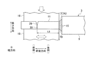
接合部位形成工程では、まず、長手方向(長さ方向)の一部(たとえば前端部)で、所定の長さにわたって被覆9が非存在であることで(たとえば、被覆9の一部が除去されて)導体7が露出している電線3を用意する。
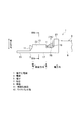
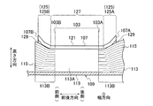
3、105 電線
5、109 端子
7、113 導体
7A、113A 露出導体
9、111 被覆
11、103 接合部位
13、107 ワイヤバレル部
15 素線
17 底板部
19 幾何中心
23 側板部
107A ワイヤバレル部の端
103A 接合部位の端
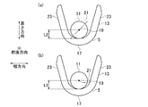
L1、L2、L3、L4、L5、L6、L7 接合部位断面の幾何中心とワイヤバレル部との間の距離
Claims (8)
- 長手方向の一部で、所定の長さにわたって被覆が非存在であることで導体が露出している電線の、前記露出している導体の長手方向の少なくとも一部に、前記導体の素線同士が接合されている接合部位を形成する接合部位形成工程と、
ワイヤバレル部を備えた端子を、前記ワイヤバレル部が前記接合部位形成工程で形成された接合部位の少なくとも一部を覆うように前記電線に設置する端子設置工程と、
を有し、前記接合部位形成工程で形成され前記端子設置工程で前記端子が設置される前の前記接合部位の断面形状が、前記接合部位を前記ワイヤバレル部内で前記ワイヤバレル部に係合させつつ前記接合部位を任意の角度回転したときに、前記接合部位の断面の幾何中心と前記ワイヤバレル部との間の距離の値の変域が、「0.71〜1.29」の範囲内に収まる形状に形成されていることを特徴とする端子付き電線の製造方法。 - 請求項1に記載の端子付き電線の製造方法において、
前記距離の値の変域が、「0.8〜1.2」の範囲内に収まっていることを特徴とする端子付き電線の製造方法。 - 請求項1または請求項2に記載の端子付き電線の製造方法において、
前記接合部位形成工程で形成され前記端子設置工程で前記端子が設置される前の前記接合部位の断面形状は、円形状もしくは円に近似した形状もしくは正方形以上の数の角部を有する正多角形状もしくは正多角形状に近似した形状に形成されていることを特徴とする端子付き電線の製造方法。 - 請求項1〜請求項3のいずれか1項に記載の端子付き電線の製造方法において、
前記接合部位形成工程で形成された接合部位に設置される前の前記端子のワイヤバレル部の断面は、曲率半径が前記接合部位の円もしくは外接円の半径と等しいか僅かに大きい円弧状の底板部と一対の側板部とを備えて「U」字状に形成されており、
前記端子設置工程での前記ワイヤバレル部の設置は、前記ワイヤバレル部の内で、前記底板部内面の最も底の部位もしくはこの近傍に前記接合部位を接触させておいて、前記ワイヤバレル部をカシメることでなされることを特徴とする端子付き電線の製造方法。 - 請求項1〜請求項4のいずれか1項に記載の端子付き電線の製造方法において、
前記接合部位形成工程で、前記露出している導体の長手方向の中間部で前記露出している導体を切断することを特徴とする端子付き電線の製造方法。 - 請求項1〜請求項5のいずれか1項に記載の端子付き電線の製造方法において、
前記端子設置工程は、前記ワイヤバレル部の、前記被覆側に位置している端が、前記接合部位の、前記被覆側に位置している端よりも、前記被覆側に位置するように前記端子を前記電線に設置する工程であることを特徴とする端子付き電線の製造方法。 - 請求項6に記載の端子付き電線において、
前記電線の長手方向と前記ワイヤバレル部の前後方向とがお互いに一致しており、
前後方向で、前記接合部位が前記ワイヤバレル部の内側に位置していることを特徴とする端子付き電線の製造方法。 - 請求項1〜請求項7のいずれか1項に記載の端子付き電線の製造方法において、
複数本の前記電線に1つの前記端子が設置することを特徴とする端子付き電線。
Priority Applications (4)
| Application Number | Priority Date | Filing Date | Title |
|---|---|---|---|
| JP2017227445A JP6706605B2 (ja) | 2017-11-28 | 2017-11-28 | 端子付き電線の製造方法 |
| CN201811391446.6A CN109980481B (zh) | 2017-11-28 | 2018-11-21 | 装接有端子的电线的制造方法和装接有端子的电线 |
| DE102018220079.3A DE102018220079B4 (de) | 2017-11-28 | 2018-11-22 | Verfahren zum Fertigen einer mit einem Anschluss versehenen elektrischen Leitung |
| US16/200,910 US10826261B2 (en) | 2017-11-28 | 2018-11-27 | Method for manufacturing terminal-equipped electric wire, and terminal-equipped electric wire |
Applications Claiming Priority (1)
| Application Number | Priority Date | Filing Date | Title |
|---|---|---|---|
| JP2017227445A JP6706605B2 (ja) | 2017-11-28 | 2017-11-28 | 端子付き電線の製造方法 |
Publications (2)
| Publication Number | Publication Date |
|---|---|
| JP2019096572A true JP2019096572A (ja) | 2019-06-20 |
| JP6706605B2 JP6706605B2 (ja) | 2020-06-10 |
Family
ID=66442199
Family Applications (1)
| Application Number | Title | Priority Date | Filing Date |
|---|---|---|---|
| JP2017227445A Active JP6706605B2 (ja) | 2017-11-28 | 2017-11-28 | 端子付き電線の製造方法 |
Country Status (4)
| Country | Link |
|---|---|
| US (1) | US10826261B2 (ja) |
| JP (1) | JP6706605B2 (ja) |
| CN (1) | CN109980481B (ja) |
| DE (1) | DE102018220079B4 (ja) |
Families Citing this family (10)
| Publication number | Priority date | Publication date | Assignee | Title |
|---|---|---|---|---|
| DE102017124693B3 (de) * | 2017-10-23 | 2018-11-29 | Lisa Dräxlmaier GmbH | Verfahren zum stoffschlüssigen Fügen einer elektrischen Leitung an ein elektrisches Kontaktteil |
| JP2019096569A (ja) * | 2017-11-28 | 2019-06-20 | 矢崎総業株式会社 | 端子付き電線、端子付き電線の製造方法および電線 |
| JP6670282B2 (ja) * | 2017-11-28 | 2020-03-18 | 矢崎総業株式会社 | 端子付き電線および端子付き電線の製造方法 |
| JP2019121467A (ja) | 2017-12-28 | 2019-07-22 | 株式会社オートネットワーク技術研究所 | 端子付き電線、及び端子付き電線の製造方法 |
| JP2021041415A (ja) * | 2019-09-06 | 2021-03-18 | 矢崎総業株式会社 | 超音波加工装置及び超音波加工方法 |
| CN115298904A (zh) | 2020-05-27 | 2022-11-04 | 古河电气工业株式会社 | 带端子的电线、线束、端子、端子压接刀模、带端子的电线的制造方法 |
| JP7234188B2 (ja) * | 2020-07-22 | 2023-03-07 | 矢崎総業株式会社 | 電線の製造方法および電線製造装置 |
| DE102020131708B3 (de) * | 2020-11-30 | 2022-04-14 | Wieland Electric Gmbh | Ultraschallverdichten von Litzen |
| DE102021109290B4 (de) * | 2021-04-14 | 2024-11-21 | Te Connectivity Germany Gmbh | Werkzeug zur Herstellung einer Anordnung |
| CN121097471B (zh) * | 2025-08-28 | 2026-04-17 | 浙江上加电力科技有限公司 | 一种接线端子接线优化方法及系统 |
Citations (5)
| Publication number | Priority date | Publication date | Assignee | Title |
|---|---|---|---|---|
| US6393924B1 (en) * | 1997-11-10 | 2002-05-28 | Schunk Ultraschalltechnik Gmbh | Testing method for non-destructive testing of a welded connector, a testing device and an ultrasonic welding apparatus having such a device |
| JP2003338327A (ja) * | 2002-05-20 | 2003-11-28 | Yazaki Corp | 端 子 |
| WO2010058786A1 (ja) * | 2008-11-19 | 2010-05-27 | 株式会社オートネットワーク技術研究所 | 端子金具付き電線及び端子金具付き電線の製造方法 |
| JP2011081918A (ja) * | 2009-10-02 | 2011-04-21 | Sumitomo Wiring Syst Ltd | 電線の止水構造および該止水構造の形成方法 |
| JP2016115505A (ja) * | 2014-12-15 | 2016-06-23 | 株式会社オートネットワーク技術研究所 | 車載ネットワークにおける幹線構造、及び車載ネットワーク用コネクタ |
Family Cites Families (13)
| Publication number | Priority date | Publication date | Assignee | Title |
|---|---|---|---|---|
| US5532433A (en) * | 1991-11-13 | 1996-07-02 | Yazaki Corporation | Waterproof-type terminal connection structure and method of producing same |
| DE19581647D2 (de) | 1994-04-18 | 1998-07-23 | Bema Gmbh | Verfahren und Vorrichtung zur Erzeugung eines festen Litzenendes sowie Litze |
| JP2003338328A (ja) * | 2002-05-20 | 2003-11-28 | Yazaki Corp | 溶接端子及びその溶接装置 |
| JP4374187B2 (ja) * | 2002-12-20 | 2009-12-02 | 矢崎総業株式会社 | 端子と被覆電線との接続方法 |
| JP2005302448A (ja) * | 2004-04-09 | 2005-10-27 | Yazaki Corp | 被覆電線の端末接続方法、スリーブ仮接続用プレス装置及び電線接続用導電性スリーブ |
| JP4951356B2 (ja) * | 2007-01-18 | 2012-06-13 | 矢崎総業株式会社 | 圧着機及び電線付き端子金具 |
| JP5196535B2 (ja) * | 2007-12-20 | 2013-05-15 | 矢崎総業株式会社 | アルミニウム電線に対する端子圧着方法 |
| JP5017156B2 (ja) | 2008-03-24 | 2012-09-05 | 矢崎総業株式会社 | 電線に対する端子の圧着方法 |
| ITTO20090034A1 (it) | 2009-01-19 | 2010-07-20 | Boggio Elisabetta | Metodo per collegare un cavo elettrico in alluminio ad un terminale o capocorda in bronzo o in ottone e relativo assieme di collegamento. |
| JP5374208B2 (ja) * | 2009-03-27 | 2013-12-25 | 矢崎総業株式会社 | 圧着端子金具 |
| JP5482324B2 (ja) | 2010-03-12 | 2014-05-07 | 住友電装株式会社 | 端子付電線の製造方法及び端子付電線 |
| JP2011222311A (ja) | 2010-04-09 | 2011-11-04 | Yazaki Corp | 電線接続方法及びワイヤハーネス |
| JP6163149B2 (ja) * | 2014-12-15 | 2017-07-12 | 株式会社オートネットワーク技術研究所 | 端子付き電線の製造方法 |
-
2017
- 2017-11-28 JP JP2017227445A patent/JP6706605B2/ja active Active
-
2018
- 2018-11-21 CN CN201811391446.6A patent/CN109980481B/zh active Active
- 2018-11-22 DE DE102018220079.3A patent/DE102018220079B4/de active Active
- 2018-11-27 US US16/200,910 patent/US10826261B2/en active Active
Patent Citations (5)
| Publication number | Priority date | Publication date | Assignee | Title |
|---|---|---|---|---|
| US6393924B1 (en) * | 1997-11-10 | 2002-05-28 | Schunk Ultraschalltechnik Gmbh | Testing method for non-destructive testing of a welded connector, a testing device and an ultrasonic welding apparatus having such a device |
| JP2003338327A (ja) * | 2002-05-20 | 2003-11-28 | Yazaki Corp | 端 子 |
| WO2010058786A1 (ja) * | 2008-11-19 | 2010-05-27 | 株式会社オートネットワーク技術研究所 | 端子金具付き電線及び端子金具付き電線の製造方法 |
| JP2011081918A (ja) * | 2009-10-02 | 2011-04-21 | Sumitomo Wiring Syst Ltd | 電線の止水構造および該止水構造の形成方法 |
| JP2016115505A (ja) * | 2014-12-15 | 2016-06-23 | 株式会社オートネットワーク技術研究所 | 車載ネットワークにおける幹線構造、及び車載ネットワーク用コネクタ |
Also Published As
| Publication number | Publication date |
|---|---|
| US10826261B2 (en) | 2020-11-03 |
| DE102018220079B4 (de) | 2024-08-01 |
| CN109980481B (zh) | 2021-06-25 |
| US20190165535A1 (en) | 2019-05-30 |
| DE102018220079A1 (de) | 2019-05-29 |
| CN109980481A (zh) | 2019-07-05 |
| JP6706605B2 (ja) | 2020-06-10 |
Similar Documents
| Publication | Publication Date | Title |
|---|---|---|
| JP2019096572A (ja) | 端子付き電線の製造方法および端子付き電線 | |
| JP6674433B2 (ja) | 端子付き電線および端子付き電線の製造方法 | |
| JP6670282B2 (ja) | 端子付き電線および端子付き電線の製造方法 | |
| JP6655056B2 (ja) | 電線の導体の超音波接合方法、端子付き電線の製造方法および電線 | |
| JP5601259B2 (ja) | 端子金具 | |
| US10511105B2 (en) | Electric wire with terminal and method of manufacturing electric wire with terminal | |
| JP6785210B2 (ja) | 電線の導体の超音波接合方法、端子付き電線の製造方法および超音波接合装置 | |
| CN110021827A (zh) | 装接有端子的电线、装接有端子的电线的制造方法和电线 | |
| CN103718394A (zh) | 将线缆焊接至端子的方法以及由此获得的端子 | |
| US11791599B2 (en) | Electric cable with terminal and method for manufacturing electric cable with terminal | |
| JP2019153420A (ja) | 電線の導体の接合方法および電線 | |
| JP2025074603A (ja) | ホーン及び超音波接合装置 | |
| TWI336892B (en) | Flat cable | |
| JP2021010947A (ja) | 平角導線の切断方法および平角導線 | |
| US10673150B2 (en) | Terminal-bonded cable | |
| JP2005144532A (ja) | 超音波溶接装置及び超音波溶接方法 | |
| JP5797032B2 (ja) | 電線接続端子 | |
| JP2005297055A (ja) | 超音波接合用ホーン | |
| JP2021044176A (ja) | 端子金具、端子付き電線、および端子システム | |
| JP2023170508A (ja) | 端子、端子付き電線 | |
| JP2017004844A (ja) | 端子付き電線及びその製造方法 | |
| JP2020004641A (ja) | 端子付電線及びその製造方法 | |
| JP2021044177A (ja) | 端子金具、および端子付き電線 | |
| WO2017187955A1 (ja) | 導電部材 | |
| JP2016207306A (ja) | 端子および端子付き電線 |
Legal Events
| Date | Code | Title | Description |
|---|---|---|---|
| A621 | Written request for application examination |
Free format text: JAPANESE INTERMEDIATE CODE: A621 Effective date: 20190117 |
|
| A131 | Notification of reasons for refusal |
Free format text: JAPANESE INTERMEDIATE CODE: A131 Effective date: 20190910 |
|
| A977 | Report on retrieval |
Free format text: JAPANESE INTERMEDIATE CODE: A971007 Effective date: 20190913 |
|
| A521 | Request for written amendment filed |
Free format text: JAPANESE INTERMEDIATE CODE: A523 Effective date: 20191030 |
|
| A131 | Notification of reasons for refusal |
Free format text: JAPANESE INTERMEDIATE CODE: A131 Effective date: 20200128 |
|
| A521 | Request for written amendment filed |
Free format text: JAPANESE INTERMEDIATE CODE: A523 Effective date: 20200326 |
|
| TRDD | Decision of grant or rejection written | ||
| A01 | Written decision to grant a patent or to grant a registration (utility model) |
Free format text: JAPANESE INTERMEDIATE CODE: A01 Effective date: 20200512 |
|
| A61 | First payment of annual fees (during grant procedure) |
Free format text: JAPANESE INTERMEDIATE CODE: A61 Effective date: 20200518 |
|
| R150 | Certificate of patent or registration of utility model |
Ref document number: 6706605 Country of ref document: JP Free format text: JAPANESE INTERMEDIATE CODE: R150 |
|
| R250 | Receipt of annual fees |
Free format text: JAPANESE INTERMEDIATE CODE: R250 |
|
| S531 | Written request for registration of change of domicile |
Free format text: JAPANESE INTERMEDIATE CODE: R313531 |
|
| R350 | Written notification of registration of transfer |
Free format text: JAPANESE INTERMEDIATE CODE: R350 |
|
| R250 | Receipt of annual fees |
Free format text: JAPANESE INTERMEDIATE CODE: R250 |
|
| R250 | Receipt of annual fees |
Free format text: JAPANESE INTERMEDIATE CODE: R250 |