JP2019161069A - Electrical equipment - Google Patents
Electrical equipment Download PDFInfo
- Publication number
- JP2019161069A JP2019161069A JP2018047194A JP2018047194A JP2019161069A JP 2019161069 A JP2019161069 A JP 2019161069A JP 2018047194 A JP2018047194 A JP 2018047194A JP 2018047194 A JP2018047194 A JP 2018047194A JP 2019161069 A JP2019161069 A JP 2019161069A
- Authority
- JP
- Japan
- Prior art keywords
- packing
- housing
- joint
- flange
- diagonal line
- Prior art date
- Legal status (The legal status is an assumption and is not a legal conclusion. Google has not performed a legal analysis and makes no representation as to the accuracy of the status listed.)
- Pending
Links
Images
Landscapes
- Gasket Seals (AREA)
- Casings For Electric Apparatus (AREA)
- Inverter Devices (AREA)
Abstract
【課題】パッキンの接合部にて雨水等が侵入し難い電気機器を提供する。【解決手段】筐体(11)は、開口部(20)と、開口部(20)から外側に延在する方形状のフランジ部(21)とを備える。蓋体(12)は、筐体(11)の開口部(20)およびフランジ部(21)を覆い、筐体(11)のフランジ部(21)に取り付けられる。パッキン(13)は、フランジ部(21)と蓋体(12)との間に設けられる。筐体(11)は、絞り加工で形成されており、パッキン(13)は、複数の紐状部材(40)〜(43)を接合部(44)にて連結したものであり、接合部(44)は、フランジ部(21)の隅部(22)に位置する。【選択図】図4PROBLEM TO BE SOLVED: To provide an electric device in which rainwater or the like is hard to enter at a joint of packing. A housing (11) includes an opening (20) and a rectangular flange portion (21) extending outward from the opening (20). The lid (12) covers the opening (20) and the flange (21) of the housing (11) and is attached to the flange (21) of the housing (11). The packing (13) is provided between the flange portion (21) and the lid (12). The housing (11) is formed by drawing, and the packing (13) is formed by connecting a plurality of string-shaped members (40) to (43) at a joint portion (44), and the joint portion (13). 44) is located at the corner (22) of the flange portion (21). [Selection diagram] FIG. 4
Description
本発明は、例えば、パワーコンディショナ等の電気機器に関する。具体的には、本発明は、上記電気機器における筐体および蓋体の間を密閉するためのパッキンに関する。 The present invention relates to an electric device such as a power conditioner. Specifically, this invention relates to the packing for sealing between the housing | casing and cover bodies in the said electric equipment.
多くの電気機器は、電気部品を収容する筐体と、該筐体の開口部およびフランジ部を覆う蓋体とを備えている。また、風雨に曝される電気機器には、雨水等の侵入を防止するためのパッキンが上記筐体のフランジ部と上記蓋体との間に設けられている。 Many electrical devices include a housing that houses electrical components and a lid that covers an opening and a flange portion of the housing. In addition, a packing for preventing intrusion of rainwater or the like is provided between the flange portion of the casing and the lid body in an electrical device exposed to wind and rain.
上記パッキンを、シート状の弾性部材からの打ち抜きで形成する場合、上記パッキンの開口に対応する部分の材料が無駄となる。そこで、特許文献1では、上記パッキンを、複数の紐状部材に分割し、隣り合う紐状部材どうしを接合している。 When the packing is formed by punching from a sheet-like elastic member, the material corresponding to the opening of the packing is wasted. So, in patent document 1, the said packing is divided | segmented into several string-like members, and the adjacent string-like members are joined.
特許文献1のようなパッキンの場合、隣り合う紐状部材どうしが接合された接合部において、雨水等の侵入を防止するような工夫が必要である。そこで、特許文献1に記載のパッキンでは、接合部は、雨水等の侵入経路を長くするために、複数の接合面を有している。 In the case of the packing as in Patent Document 1, it is necessary to devise measures to prevent intrusion of rainwater or the like at a joint portion where adjacent string-like members are joined together. So, in the packing of patent document 1, in order to lengthen the penetration | invasion path | routes, such as rain water, a junction part has a some junction surface.
しかしながら、上記侵入を防止するには、上記パッキンだけでなく、上記筐体および上記蓋体の特徴も考慮する必要がある。本開示の一態様は、パッキンの接合部にて雨水等が侵入し難い電気機器を提供することを目的とする。 However, in order to prevent the intrusion, it is necessary to consider not only the packing but also the characteristics of the housing and the lid. An object of one embodiment of the present disclosure is to provide an electrical device in which rainwater or the like hardly enters at a joint portion of the packing.
上記の課題を解決するために、本開示の一態様に係る電気機器は、電気部品を収容する角型の筐体であって開口部と、該開口部から外側に延在する方形状のフランジ部とを備える筐体と、該筐体の開口部およびフランジ部を覆い、前記筐体のフランジ部に取り付けられる蓋体と、前記筐体のフランジ部と前記蓋体との間に設けられたパッキンとを備える電気機器であって、前記筐体は、絞り加工で形成されており、前記パッキンは、複数の紐状部材を接合部にて連結したものであり、前記接合部は、前記フランジ部の隅部に位置する。 In order to solve the above-described problem, an electrical device according to an aspect of the present disclosure is a rectangular housing that houses electrical components, and includes an opening and a rectangular flange that extends outward from the opening. A cover that covers the opening and the flange of the casing and is attached to the flange of the casing, and is provided between the flange of the casing and the lid An electrical device including a packing, wherein the casing is formed by drawing, and the packing is formed by connecting a plurality of string-like members at a joint portion, and the joint portion includes the flange. Located in the corner of the part.
ところで、角型の筐体を絞り加工で形成する場合、側壁の傾き等を調整する必要があるが、このような調整を行っても、前記筐体におけるフランジ部の隅部は傾斜し難い。 By the way, when a square casing is formed by drawing, it is necessary to adjust the inclination of the side wall and the like. However, even if such an adjustment is performed, the corner portion of the flange portion in the casing is not easily inclined.
そこで、前記の構成によると、角型の筐体は、絞り加工で形成されており、パッキンの接合部は、前記筐体におけるフランジ部の隅部に位置する。従って、前記パッキンの接合部が、前記フランジ部に密着することができ、前記パッキンの接合部にて雨水等が侵入し難くなる。 Therefore, according to the above configuration, the rectangular casing is formed by drawing, and the joint portion of the packing is located at the corner of the flange portion of the casing. Accordingly, the joint portion of the packing can be in close contact with the flange portion, and rainwater or the like hardly enters at the joint portion of the packing.
前記電気機器では、前記蓋体は、前記筐体のフランジ部にて締結されることが好ましい。この場合、前記パッキンの接合部が前記蓋体および前記筐体のフランジ部に良好に密着することができ、前記パッキンの接合部にて雨水等がさらに侵入し難くなる。 In the electric device, it is preferable that the lid is fastened at a flange portion of the casing. In this case, the joint portion of the packing can be in good contact with the lid and the flange portion of the housing, and rainwater and the like are less likely to enter the joint portion of the packing.
ところで、前記フランジ部の隅部は、隅部どうしの対角線を含む位置が、前記のような調整を行っても最も傾斜し難い。そこで、前記電気機器では、前記接合部は、前記フランジ部の隅部どうしの対角線の方向を含む接合面、または、前記対角線と交わる接合面を有することが好ましい。この場合、前記パッキンの接合部が、前記フランジ部にさらに密着することができ、前記パッキンの接合部にて雨水等がさらに侵入し難くなる。 By the way, the corner portion of the flange portion is most difficult to be inclined even if the position including the diagonal line between the corner portions is adjusted as described above. Therefore, in the electric device, it is preferable that the joint portion has a joint surface including a diagonal direction between corners of the flange portion or a joint surface intersecting with the diagonal line. In this case, the joint portion of the packing can be further adhered to the flange portion, and rainwater or the like is less likely to enter the joint portion of the packing.
前記電気機器では、前記接合部は、前記フランジ部の隅部どうしの対角線に平行な接合面、または前記対角線の方向を含む接合面と、前記対角線に垂直な接合面とを有することが好ましい。この場合、前記対角線に平行な接合面、または前記対角線の方向を含む接合面における隙間と、前記対角線に垂直な接合面における隙間とが略垂直となるため、一方の隙間に侵入した雨水等が他方の隙間に侵入し難くなる。その結果、雨水等がさらに侵入し難くなる。 In the electric device, it is preferable that the joint portion has a joint surface parallel to a diagonal line between corners of the flange portion, or a joint surface including a direction of the diagonal line, and a joint surface perpendicular to the diagonal line. In this case, since the gap in the joint surface parallel to the diagonal line or the joint surface including the direction of the diagonal line and the gap in the joint surface perpendicular to the diagonal line are substantially perpendicular, rainwater or the like that has entered one gap It becomes difficult to enter the other gap. As a result, rainwater or the like becomes more difficult to enter.
ところで、角型の筐体を絞り加工で形成する場合、開口部の隅部は湾曲した形状となる。そこで、前記パッキンは、前記フランジ部の隅部にて湾曲する湾曲部を備えることが好ましい。この場合、前記接合部は、前記湾曲部に位置することになり、前記パッキンは、前記筐体の開口部に対応した形状となり、前記パッキンの接合部にて雨水等がさらに侵入し難くなる。 By the way, when a rectangular housing is formed by drawing, the corner of the opening has a curved shape. Therefore, it is preferable that the packing includes a bending portion that bends at a corner portion of the flange portion. In this case, the joint portion is located at the curved portion, and the packing has a shape corresponding to the opening of the casing, and rainwater or the like is more difficult to enter at the joint portion of the packing.
本開示の一態様によれば、パッキンの接合部にて雨水等が侵入し難い電気機器を提供することができる。 According to one embodiment of the present disclosure, it is possible to provide an electrical device in which rainwater or the like hardly enters at a joint portion of the packing.
以下、本開示の一側面に係る実施の形態(以下、「本実施形態」とも表記する)を、図面に基づいて説明する。 Hereinafter, an embodiment according to an aspect of the present disclosure (hereinafter also referred to as “this embodiment”) will be described with reference to the drawings.
§1 適用例
まず、図4に基づいて、本開示が適用される場面の一例について説明する。
§1 Application Example First, an example of a scene to which the present disclosure is applied will be described based on FIG.
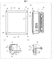
図4は、蓋体を取り付けたパワーコンディショナの構成を示す図である。図4の(a)は正面図である。図4の(b)および(c)は、図4の(a)のA−A線における矢視断面図であって、上記パワーコンディショナの前側上部および前側下部をそれぞれ示す図である。 FIG. 4 is a diagram illustrating a configuration of a power conditioner to which a lid is attached. FIG. 4A is a front view. FIGS. 4B and 4C are cross-sectional views taken along the line AA in FIG. 4A, and show the front upper portion and the front lower portion of the power conditioner, respectively.
図4に示すように、パワーコンディショナ10(電気機器)は、電気部品を収容する角型の筐体11であって開口部20と、該開口部20から外側に延在する方形状のフランジ部21とを備える筐体11と、該筐体11の開口部20およびフランジ部21を覆い、筐体11のフランジ部21に取り付けられる蓋体12と、筐体11のフランジ部21と蓋体12との間に設けられたパッキン13とを備える。
As shown in FIG. 4, the power conditioner 10 (electrical device) is a
筐体11は、絞り加工で形成されており、パッキン13は、複数の紐状部材40〜43を接合部44にて連結したものであり、接合部44は、フランジ部21の隅部22に位置する。
The
ところで、角型の筐体11を絞り加工で形成する場合、側壁の傾き等を調整する必要があるが、このような調整を行っても、筐体11におけるフランジ部21の隅部22は傾斜し難い。
By the way, when the
そこで、上記の構成によると、角型の筐体11は、絞り加工で形成されており、パッキン13の接合部44は、筐体11におけるフランジ部21の隅部22に位置する。従って、パッキン13の接合部44が、フランジ部21に密着することができ、パッキン13の接合部44にて雨水等が侵入し難くなる。
Therefore, according to the above configuration, the
§2 構成例
本開示の実施の形態について図1〜図5に基づいて説明する。
§2 Configuration example An embodiment of the present disclosure will be described with reference to FIGS.
(パワーコンディショナの構成)
本実施の形態のパワーコンディショナは、太陽光発電を利用した系統連系システムに用いられるパワーコンディショナ(Power Conditioning System)である。
(Configuration of inverter)
The power conditioner of this Embodiment is a power conditioner (Power Conditioning System) used for the grid connection system using photovoltaic power generation.
系統連系システムは、住宅の屋根等に設置する複数の太陽電池と、各太陽電池により発電された直流電力を交流電力に変換するパワーコンディショナとで構成される。そして、この系統連系システムは、パワーコンディショナと商用電力系統との間に接続された負荷に対して、系統連系運転と自立運転との何れか一方に切り替えて交流電力を供給するものである。ここで、系統連系運転とは、パワーコンディショナと商用電力系統とを連系して運転することを示す。また、自立運転とは、例えば商用電力系統が停電している場合等に、パワーコンディショナのみを運転することを示す。 The grid interconnection system includes a plurality of solar cells installed on a roof of a house and a power conditioner that converts DC power generated by each solar cell into AC power. This grid interconnection system supplies AC power to the load connected between the power conditioner and the commercial power grid by switching to either grid grid operation or independent operation. is there. Here, the grid interconnection operation means that the power conditioner and the commercial power system are linked and operated. In addition, the self-sustained operation indicates that only the power conditioner is operated, for example, when the commercial power system has a power failure.
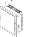
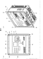
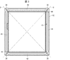
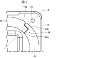
図1は、パワーコンディショナ10の構成を示す斜視図である。図2は、蓋体12を外したパワーコンディショナ10の構成を示す図である。図2の(a)は正面図である。図2の(b)はパワーコンディショナ10を下側から見上げた斜視図である。図3は、蓋体12およびパッキン13の構成を示す背面図である。図5は、図3に示す蓋体12の隅部における蓋体12およびパッキン13の構成を示す背面図である。なお、本願においては、正面側を前側と称し、背面側を後側と称する場合がある。
FIG. 1 is a perspective view showing the configuration of the
図1〜図5に示すように、パワーコンディショナ10は、略直方体の筐体11と、蓋体12と、筐体11および蓋体12の間を密閉するパッキン13とを備える。
As shown in FIGS. 1 to 5, the
筐体11は、内部に各種の電気部品を収容し、外部の背面にファン、放熱板等が設けられている。筐体11は、前側に略方形状の開口部20と、該開口部20から外側に延在する略方形状のフランジ部21とを備える。筐体11は、金属製であり、絞り加工によって形成されている。このため、筐体11の開口部20は、4つの隅部において湾曲している。また、フランジ部21の4つの隅部22には孔部23が設けられている。
The
蓋体12は、筐体11の開口部20およびフランジ部21を覆う略方形の板状部材である。蓋体12の4隅には、孔部30が設けられている。蓋体12は、ボルト14およびナット15により筐体11に取り付け可能となっている。
The
パッキン13は、蓋体12と筐体11のフランジ部21との間に設けられる。パッキン13は、ゴム等によって形成された弾性部材である。パッキン13は、筐体11の開口部20に対応する形状であり、該開口部20よりも稍大きいサイズとなっている。従って、パッキン13は、フランジ部21の隅部22において湾曲する湾曲部を有し、その他の部分では直線状である直線部を有している。
The packing 13 is provided between the
本実施形態では、パッキン13は、4本の紐状部材40〜43からなり、隣り合う紐状部材40〜43どうしは、フランジ部21の隅部22にて接合している。すなわち、パッキン13の接合部44は、上記湾曲部に位置することになる。
In the present embodiment, the packing 13 includes four
これにより、上述のように、パッキン13の接合部44が、フランジ部21に密着することができ、パッキン13の接合部44にて雨水等が侵入し難くなる。また、パッキン13は、筐体11の開口部20に対応した形状となり、パッキン13の接合部44にて雨水等がさらに侵入し難くなる。
As a result, as described above, the
なお、上下の紐状部材40・42は同じ形状であり、左右の紐状部材41・43は同じ形状である。すなわち、本実施形態では、2種類の紐状部材を生成すればよいため、生産性が向上する。
The upper and lower string-
(パワーコンディショナの組み立て方法)
上記構成のパワーコンディショナ10は、下記のように組み立てられる。すなわち、まず、筐体11内に電気部品を収容する。また、蓋体12の背面にパッキン13を取り付ける。なお、蓋体12においてパッキン13が取り付けられる面は平坦な面である。
(How to assemble the inverter)
The
次に、筐体11の開口部20およびフランジ部21を覆うように蓋体12を取り付ける。なお、フランジ部21においてパッキン13が接触する面は平坦な面である。そして、ボルト14を蓋体12の孔部30および筐体11の孔部23を貫通させ、貫通させたボルト14にナット15を螺合することにより、蓋体12が筐体11に締結される。従って、パッキン13の接合部44が蓋体12および筐体11のフランジ部21に良好に密着することができ、パッキン13の接合部44にて雨水等がさらに侵入し難くなる。なお、筐体11および蓋体12の間には、パッキン13が押し潰されることを防止するためのスペーサが設けられていることが望ましい。
Next, the
(変形例)
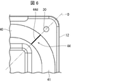
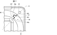
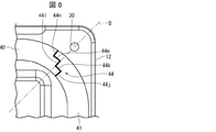
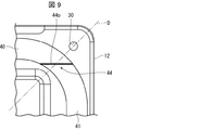
図6〜図9は、図5と同様の背面図であり、パッキン13の接合部44の変形例を示す図である。
(Modification)
6 to 9 are rear views similar to FIG. 5, and are diagrams showing modifications of the
上記実施形態では、図5に示すように、紐状部材40・41どうしの接合部44は、対角線Dに平行な2つの接合面44a・44bと、対角線Dに垂直な1つの接合面44cとを有し、接合面44cは、対角線Dと垂直に交わっている。
In the above embodiment, as shown in FIG. 5, the
一方、図6の例では、接合部44は、対角線Dに平行な1つの接合面44dを有し、接合面44dは、対角線Dの方向を含んでいる。また、図7の例では、接合部44は、対角線Dに平行な3つの接合面44e〜44gと、対角線Dに垂直な2つの接合面44h・44iとを有し、接合面44e・44gは、対角線Dの方向を含んでいる。
On the other hand, in the example of FIG. 6, the
また、図8の例では、接合部44は、対角線Dに平行な3つの接合面44j〜44lと、対角線Dに垂直な2つの接合面44m・44nとを有し、接合面44kは、対角線Dの方向を含んでいる。また、図9の例では、接合部44は、対角線Dと交わる接合面44oを有する。
In the example of FIG. 8, the
ところで、フランジ部21の隅部22は、隅部22どうしの対角線Dを含む位置が、絞り加工の調整を行っても最も傾斜し難い。そこで、接合部44は、図6・図7・図8に示すように対角線Dの方向を含む接合面、または、図5・図9に示すように対角線Dと交わる接合面を有することが望ましい。この場合、パッキン13の接合部44が、フランジ部21にさらに密着することができ、パッキン13の接合部44にて雨水等がさらに侵入し難くなる。
By the way, the
また、接合部44は、図5・図7・図8に示すように、対角線Dに平行な接合面、または対角線Dの方向を含む接合面と、対角線Dに垂直な接合面とを有することがさらに望ましい。この場合、対角線Dに平行な接合面、または対角線Dの方向を含む接合面における隙間と、対角線Dに垂直な接合面における隙間とが略垂直となるため、一方の隙間に侵入した雨水等が他方の隙間に侵入し難くなる。その結果、雨水等がさらに侵入し難くなる。
Further, as shown in FIGS. 5, 7, and 8, the
なお、対角線Dの方向を含む接合面は、対角線から或る程度傾いた方向を含む接合面であってもよい。この傾きは、対角線Dから±15度程度であればよく、対角線Dから±10度程度であればさらによく、対角線Dから±5度程度であれば最もよい。 Note that the joint surface including the direction of the diagonal line D may be a joint surface including a direction inclined to some extent from the diagonal line. The inclination may be about ± 15 degrees from the diagonal D, more preferably about ± 10 degrees from the diagonal D, and most preferably about ± 5 degrees from the diagonal D.
(付記事項)
上記実施形態では、パッキン13は、4つの紐状部材40〜43が4つの隅部22にて接合しているが、これに限定されるものではない。パッキン13は、2つの紐状部材が2つの隅部22にて接合していてもよいし、3つの紐状部材が3つの隅部22にて接合していてもよい。
(Additional notes)
In the said embodiment, although the four string-like members 40-43 have joined the packing 13 in the four
上記実施形態では、パワーコンディショナ10に本発明を適用しているが、これに限定されるものではない。電気部品を収容する筐体と、該筐体の開口部を覆う蓋体とを備える電気機器であれば、本発明を適用することができる。
In the said embodiment, although this invention is applied to the
本発明は上述した各実施形態に限定されるものではなく、請求項に示した範囲で種々の変更が可能であり、異なる実施形態にそれぞれ開示された技術的手段を適宜組み合わせて得られる実施形態についても本発明の技術的範囲に含まれる。 The present invention is not limited to the above-described embodiments, and various modifications are possible within the scope shown in the claims, and embodiments obtained by appropriately combining technical means disclosed in different embodiments. Is also included in the technical scope of the present invention.
10 パワーコンディショナ(電気機器)
11 筐体
12 蓋体
13 パッキン
14 ボルト
15 ナット
20 開口部
21 フランジ部
22 隅部
23、30 孔部
40〜43 紐状部材
44 接合部
44a〜44o 接合面
D 対角線
10 Power conditioner (electric equipment)
DESCRIPTION OF
Claims (5)
該筐体の開口部およびフランジ部を覆い、前記筐体のフランジ部に取り付けられる蓋体と、
前記筐体のフランジ部と前記蓋体との間に設けられたパッキンとを備える電気機器であって、
前記筐体は、絞り加工で形成されており、
前記パッキンは、複数の紐状部材を接合部にて連結したものであり、
前記接合部は、前記フランジ部の隅部に位置することを特徴とする電気機器。 A rectangular housing that accommodates electrical components, the housing comprising an opening and a rectangular flange extending outward from the opening;
A lid that covers the opening and the flange of the housing and is attached to the flange of the housing;
An electrical device comprising a packing provided between a flange portion of the housing and the lid,
The housing is formed by drawing,
The packing is obtained by connecting a plurality of string-like members at a joint portion,
The electric device according to claim 1, wherein the joint portion is located at a corner of the flange portion.
Priority Applications (1)
| Application Number | Priority Date | Filing Date | Title |
|---|---|---|---|
| JP2018047194A JP2019161069A (en) | 2018-03-14 | 2018-03-14 | Electrical equipment |
Applications Claiming Priority (1)
| Application Number | Priority Date | Filing Date | Title |
|---|---|---|---|
| JP2018047194A JP2019161069A (en) | 2018-03-14 | 2018-03-14 | Electrical equipment |
Publications (1)
| Publication Number | Publication Date |
|---|---|
| JP2019161069A true JP2019161069A (en) | 2019-09-19 |
Family
ID=67992662
Family Applications (1)
| Application Number | Title | Priority Date | Filing Date |
|---|---|---|---|
| JP2018047194A Pending JP2019161069A (en) | 2018-03-14 | 2018-03-14 | Electrical equipment |
Country Status (1)
| Country | Link |
|---|---|
| JP (1) | JP2019161069A (en) |
Cited By (1)
| Publication number | Priority date | Publication date | Assignee | Title |
|---|---|---|---|---|
| JP7618333B2 (en) | 2019-12-02 | 2025-01-21 | エルジー エナジー ソリューション リミテッド | Battery pack and device including same |
Citations (6)
| Publication number | Priority date | Publication date | Assignee | Title |
|---|---|---|---|---|
| JPS52114132U (en) * | 1976-02-27 | 1977-08-30 | ||
| JPH022565U (en) * | 1988-06-17 | 1990-01-09 | ||
| JPH11325250A (en) * | 1998-05-08 | 1999-11-26 | Gastar Corp | Packing, sealing structure, gas hot-water supply device and manufacture of packing |
| JP2011192782A (en) * | 2010-03-15 | 2011-09-29 | Omron Corp | Packing structure |
| JP3172419U (en) * | 2011-10-06 | 2011-12-15 | 木谷電器株式会社 | Connection box for photovoltaic system |
| JP2018006532A (en) * | 2016-06-30 | 2018-01-11 | 古野電気株式会社 | Display apparatus |
-
2018
- 2018-03-14 JP JP2018047194A patent/JP2019161069A/en active Pending
Patent Citations (6)
| Publication number | Priority date | Publication date | Assignee | Title |
|---|---|---|---|---|
| JPS52114132U (en) * | 1976-02-27 | 1977-08-30 | ||
| JPH022565U (en) * | 1988-06-17 | 1990-01-09 | ||
| JPH11325250A (en) * | 1998-05-08 | 1999-11-26 | Gastar Corp | Packing, sealing structure, gas hot-water supply device and manufacture of packing |
| JP2011192782A (en) * | 2010-03-15 | 2011-09-29 | Omron Corp | Packing structure |
| JP3172419U (en) * | 2011-10-06 | 2011-12-15 | 木谷電器株式会社 | Connection box for photovoltaic system |
| JP2018006532A (en) * | 2016-06-30 | 2018-01-11 | 古野電気株式会社 | Display apparatus |
Cited By (1)
| Publication number | Priority date | Publication date | Assignee | Title |
|---|---|---|---|---|
| JP7618333B2 (en) | 2019-12-02 | 2025-01-21 | エルジー エナジー ソリューション リミテッド | Battery pack and device including same |
Similar Documents
| Publication | Publication Date | Title |
|---|---|---|
| JP5279829B2 (en) | Terminal box and solar cell module | |
| CN112889356B (en) | Housing for electrical equipment and power control device | |
| JP4313303B2 (en) | Compression unit | |
| US9343600B2 (en) | Integrated microinverter housing for a PV AC module | |
| JP2015022935A (en) | Battery module | |
| JP2019161069A (en) | Electrical equipment | |
| JP3197104U (en) | Rippled roof flake and solar cell assembly including the rippled roof flake | |
| CN103326593B (en) | There is the solar inverter of sealing device | |
| JP2016157743A (en) | Electronic equipment for outdoor installation | |
| WO2020228748A1 (en) | Power supply cabinet | |
| JP7327367B2 (en) | fuel cell unit | |
| JP2017118609A (en) | Electrical equipment storage box | |
| JP6311795B2 (en) | Inverter | |
| JP2019175719A (en) | Fuel cell system | |
| JP5318198B2 (en) | Electronic equipment storage unit | |
| CN110769630A (en) | An electrical box, indoor unit and air conditioner | |
| JP5705023B2 (en) | Connection box for photovoltaic power generation | |
| JP2012033562A (en) | Solar cell module | |
| JP7456283B2 (en) | Joining structure of parts | |
| JP2025501633A (en) | Electrical equipment, electrical equipment mounting systems and solar power plants | |
| JP6016834B2 (en) | Enclosure | |
| JPWO2019064929A1 (en) | Electronics | |
| CN106100573A (en) | Lug plate and apply its photovoltaic component terminal box | |
| CN206179935U (en) | a battery box | |
| CN205986763U (en) | Lug and use its photovoltaic assembly junction box |
Legal Events
| Date | Code | Title | Description |
|---|---|---|---|
| A621 | Written request for application examination |
Free format text: JAPANESE INTERMEDIATE CODE: A621 Effective date: 20210108 |
|
| A977 | Report on retrieval |
Free format text: JAPANESE INTERMEDIATE CODE: A971007 Effective date: 20211227 |
|
| A131 | Notification of reasons for refusal |
Free format text: JAPANESE INTERMEDIATE CODE: A131 Effective date: 20220118 |
|
| A521 | Request for written amendment filed |
Free format text: JAPANESE INTERMEDIATE CODE: A523 Effective date: 20220303 |
|
| A02 | Decision of refusal |
Free format text: JAPANESE INTERMEDIATE CODE: A02 Effective date: 20220726 |