JP2019199687A - Erection tool - Google Patents
Erection tool Download PDFInfo
- Publication number
- JP2019199687A JP2019199687A JP2018092893A JP2018092893A JP2019199687A JP 2019199687 A JP2019199687 A JP 2019199687A JP 2018092893 A JP2018092893 A JP 2018092893A JP 2018092893 A JP2018092893 A JP 2018092893A JP 2019199687 A JP2019199687 A JP 2019199687A
- Authority
- JP
- Japan
- Prior art keywords
- rod
- stopper
- main body
- jig
- erection
- Prior art date
- Legal status (The legal status is an assumption and is not a legal conclusion. Google has not performed a legal analysis and makes no representation as to the accuracy of the status listed.)
- Granted
Links
Images






Landscapes
- Placing Or Removing Of Piles Or Sheet Piles, Or Accessories Thereof (AREA)
Abstract
【課題】鋼材との連結およびその解除を確実に行うことができる建込治具等を提供する。【解決手段】建込治具1は、H形鋼に連結してその建込に用いるものである。建込治具1は、柱状の本体2と、本体2の軸方向に沿って配置されたロッド7と、本体2の下端部に設けられた、H形鋼をその間に差し込むための一対の連結用プレート19と、ロッド7の軸周りの回転により一対の連結用プレート19とH形鋼に設けられたピン孔に出し入れされる連結ピン21と、ロッド7の軸周りの回転を防止するためのストッパ25と、を具備する。【選択図】図1PROBLEM TO BE SOLVED: To provide an erection jig and the like which can surely perform connection and release with a steel material. SOLUTION: An installation jig 1 is connected to an H-shaped steel and used for the installation. The installation jig 1 includes a columnar main body 2, a rod 7 arranged along the axial direction of the main body 2, and a pair of couplings provided at the lower end of the main body 2 for inserting an H-shaped steel therebetween. For preventing rotation of the rod 7 around the axis, and the connecting plate 21 that is inserted into and removed from the pair of connecting plates 19 and the pin holes provided in the H-shaped steel by rotation of the rod 7 around the axis. And a stopper 25. [Selection diagram] Figure 1
Description
本発明は、鋼材の建込治具に関するものである。 The present invention relates to a steel construction jig.
構真柱の施工は、例えば地盤を掘削した掘削部にH形鋼等の鋼材を建て込み、その下端部を構真柱杭のコンクリートに埋設固定することによって行われる。構真柱(鋼材)の天端が地盤面より下方に位置する場合は、鋼材の上端部に建込治具(ヤットコとも呼ばれる)を連結し、地上の建込治具によって鋼材を適切な深さと姿勢で保持しつつ、鋼材の下端部を埋設したコンクリートが固化するのを待つ。 The construction of the structural pillar is performed by, for example, building a steel material such as H-shaped steel in an excavated part excavating the ground and burying and fixing the lower end of the steel in the concrete of the structural pillar pile. When the top end of the structural pillar (steel material) is located below the ground surface, connect an erection jig (also called Yatco) to the upper end of the steel material, and use the erection jig on the ground to bring the steel material to an appropriate depth. The concrete with the lower end of the steel material is awaited to solidify while being held in the posture.
特許文献1、2には、このような建込治具として、下端部に設けた2枚の鋼板の孔にピンの出し入れができるものが記載されている。これらの鋼板の間にH形鋼のウェブの上端部を差し込み、鋼板の孔とH形鋼のウェブの上端部の孔にピンを挿入することで、H形鋼を建込治具に連結することができる。
構真柱の設置数が多い場合、その鋼材の全数に建込治具を連結するには費用がかかり、転用を行うため鋼材との連結およびその解除を確実に行うことができる建込治具が求められている。 When there are many structural pillars installed, it is expensive to connect the construction jig to all of the steel materials, and the construction jig that can be reliably connected to and released from the steel material for diversion. Is required.
特許文献1、2では、建込治具とH形鋼の連結を解除する際、ピンに接続したワイヤ等を地上から引っ張ることによってピンを孔から引き抜くが、このようにワイヤ等の引張操作により連結の解除を行う方法は確実性の面で懸念があった。例えばワイヤ等が何らかの障害物に引っ掛かっていたりすると、ピンの引抜をうまくできない恐れがある。
In
本発明は上述した問題点に鑑みてなされたものであり、その目的は、鋼材との連結およびその解除を確実に行うことができる建込治具等を提供することである。 This invention is made | formed in view of the problem mentioned above, The objective is to provide the erection jig etc. which can perform connection with a steel material, and its cancellation | release reliably.
前述した目的を達成するための本発明は、鋼材に連結して前記鋼材の建込に用いる建込治具であって、柱状の本体と、前記本体の軸方向に沿って配置されたロッドと、前記本体の下端部に設けられた、前記鋼材をその間に差し込むための一対の連結用プレートと、前記ロッドの軸周りの回転により、一対の前記連結用プレートおよびその間に差し込まれた前記鋼材に設けられたピン孔に出し入れされる連結ピンと、前記ロッドの軸周りの回転を防止するためのストッパと、を具備し、前記ロッドから側方に突出するハンドルが、前記ロッドの上下に複数設けられることを特徴とする建込治具である。 The present invention for achieving the above-described object is an erection jig used for erection of the steel material by being connected to a steel material, a columnar main body, and a rod arranged along the axial direction of the main body. A pair of connecting plates provided at the lower end of the main body for inserting the steel material therebetween, and a pair of connecting plates and the steel material inserted between the pair of connecting plates by rotation around the axis of the rod. A connecting pin that is inserted into and removed from the provided pin hole and a stopper for preventing rotation around the axis of the rod, and a plurality of handles that protrude laterally from the rod are provided above and below the rod. It is a built-in jig characterized by this.
本発明では、建込治具と鋼材とを連結するための連結ピンが、ロッドの軸周りの回転によって連結用プレートおよび鋼材のピン孔に出し入れされるので、ロッドの操作により建込治具と鋼材との連結およびその解除を確実に行うことができる。 In the present invention, the connecting pin for connecting the erection jig and the steel material is put in and out of the linking plate and the steel material pin hole by rotation around the axis of the rod. Connection to and release from the steel material can be performed reliably.
また、ロッドにハンドルを設けることにより、ロッドを容易に操作することができる。ハンドルは上下に設けることで、鋼材の建込時に、建込治具の連結とその解除をいずれか適当なハンドルによるロッドの操作により地上で行うことができる。またストッパによって意図しないロッドの回転により連結ピンが連結用プレートおよび鋼材のピン孔から抜け、建込治具と鋼材との連結が解除されて鋼材が建込治具から抜け落ちるのを防止することができる。 Further, the rod can be easily operated by providing a handle on the rod. By providing the handle vertically, when the steel material is installed, the construction jig can be connected and released on the ground by operating the rod with an appropriate handle. Also, it is possible to prevent the connecting pin from coming out of the connecting plate and the pin hole of the steel material due to the unintended rotation of the rod by the stopper, and the connection between the construction jig and the steel material is released and the steel material is prevented from falling out of the construction jig. it can.
前記ストッパは、前記ハンドルの位置を固定するものであることが望ましい。例えば、前記ストッパは上下動および軸周りの回転が可能な棒状の部材であり、側面に突起部が設けられ、前記突起部は、前記ストッパが通された筒状の保持部の側面に設けられた鉤状の溝に通される。
前記のようにハンドルによりロッドの操作を行う場合、ハンドルをストッパによって固定することで意図しないロッドの回転を防止できる。またストッパの突起部を上記した鉤状の溝に通すことで、ストッパの上下動と軸周りの回転によってストッパを複数の高さで固定することが可能になり、ストッパによりロッドの回転が防止された状態とそれが解除された状態とをストッパの高さによって切り替えることができる。
The stopper is preferably one that fixes the position of the handle. For example, the stopper is a rod-shaped member that can move up and down and rotate around an axis, and a protrusion is provided on a side surface, and the protrusion is provided on a side surface of a cylindrical holding portion through which the stopper is passed. It is passed through a bowl-shaped groove.
As described above, when the rod is operated by the handle, unintentional rotation of the rod can be prevented by fixing the handle with the stopper. In addition, by passing the stopper protrusion through the bowl-shaped groove described above, the stopper can be fixed at multiple heights by the vertical movement of the stopper and rotation around the axis, and the stopper prevents the rod from rotating. It is possible to switch between the released state and the released state according to the height of the stopper.
前記ロッドにアームが設けられ、前記アームが前記連結ピンを保持するピン保持部に回転可能に連結されることが望ましい。
これにより、ロッドの回転をクランク式の機構で連結ピンの出し入れ運動に好適に変換し、建込治具と鋼材との連結およびその解除をより確実に行うことができる。
It is preferable that an arm is provided on the rod, and the arm is rotatably connected to a pin holding portion that holds the connecting pin.
Accordingly, the rotation of the rod can be suitably converted into a connecting / removing movement of the connecting pin by a crank type mechanism, and the connection between the erection jig and the steel material and the release thereof can be performed more reliably.
前記本体の軸方向に沿ってプレートが取付けられ、前記プレートに前記本体の軸方向に間隔を空けて複数の孔が設けられることが望ましい。
上記の孔のうち適切なものを選び、建込治具を固定するための固定治具の取付に用いることで、建込治具を鋼材の建込深さに合わせた適切な高さで固定することができる。
Preferably, a plate is attached along the axial direction of the main body, and a plurality of holes are provided in the plate at intervals in the axial direction of the main body.
By selecting an appropriate hole from the above holes and using it for mounting a fixing jig for fixing the erection jig, the erection jig is fixed at an appropriate height that matches the erection depth of the steel material. can do.
前記本体の下端部に、前記鋼材を挟み込むための一対の挟み込みプレートが設けられ、前記本体と前記挟み込みプレートの間に板状のスペーサが1または複数枚配置されることが望ましい。
これにより、挟み込みプレート同士の間隔を鋼材の断面寸法に合わせて調整することができ、挟み込みプレートによって鋼材を適切に挟み込み、鋼材の位置ずれを防ぐことができる。
It is desirable that a pair of sandwiching plates for sandwiching the steel material is provided at the lower end of the main body, and one or more plate-like spacers are disposed between the main body and the sandwiching plate.
Thereby, the space | interval of pinching plates can be adjusted according to the cross-sectional dimension of steel materials, steel materials can be pinched appropriately with a pinching plate, and position shift of steel materials can be prevented.
本発明によれば、鋼材との連結およびその解除を確実に行うことができる建込治具等を提供することができる。 ADVANTAGE OF THE INVENTION According to this invention, the erection jig etc. which can perform connection with a steel material and its cancellation | release reliably can be provided.
以下、図面に基づいて本発明の実施形態を詳細に説明する。 Hereinafter, embodiments of the present invention will be described in detail with reference to the drawings.
(1.建込治具1)
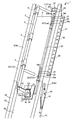
図1は本発明の実施形態に係る建込治具1(ヤットコ)を示す図である。この建込治具1は、H形鋼を地盤の掘削部に建て込んで構真柱とする際に、当該H形鋼の上端部に連結して用いられる。なお図1はH形鋼を連結する前の建込治具1を示したものである。
(1. Built-in jig 1)
FIG. 1 is a view showing an erection jig 1 (Yatco) according to an embodiment of the present invention. This
建込治具1は、本体2に、ロッド7、アーム13、ピン保持部15、連結用プレート19、連結ピン21、ストッパ25、高さ調整用プレート37、および挟み込みプレート41等を設けたものである。
The
建込治具1の本体2は柱状の部材であり、一対のフランジ3(3a、3b)とウェブ5からなるH形鋼が用いられる。
The
本体2の一方のフランジ3aの内側面付近には、本体2の軸方向に沿ってロッド7が配置される。ロッド7は、上端が本体2の上端付近に位置し、下端が本体2の下端より下方に位置する。なお、「上」は図1の上側に対応し、「下」は図1の下側に対応する。
In the vicinity of the inner surface of one
ロッド7はフランジ3aの内側面に固定された筒状のロッド保持部9の内部に通して保持され、軸周りに回転可能である。本実施形態ではロッド保持部9を上下に複数(図1の例では3つ)設けるが、ロッド保持部9の数はこれに限らない。例えばロッド7の中央付近の1ケ所のみにロッド保持部9を設けても良い。
The
ロッド7にはハンドル11が設けられる。ハンドル11はロッド7から側方に突出する棒状部材であり、本実施形態では複数のハンドル11(図1の例では2本のハンドル11a、11b)が上下に設けられる。ロッド7は、いずれかのハンドル11により操作して軸周りに回転させることができる。
A
ロッド7の下端部には、アーム13の一端が固定される。アーム13の他端はピン保持部15に連結される。
One end of the
ピン保持部15は連結ピン21を保持するものであり、対向して配置された一対の水平板15aと、両水平板15aのウェブ5側の端部に固定された鉛直板15bを有する。連結ピン21は、鉛直板15bのウェブ5側の面に固定される。
The
上記したアーム13の他端は、ピン保持部15の一対の水平板15aの間に挿入され、軸17によって水平板15aに対し回転可能に連結される。
The other end of the
本体2のウェブ5の下端部では、連結用プレート19がウェブ5の両面に1枚ずつ固定される。これら一対の連結用プレート19は、その間にH形鋼のウェブを差し込むために設けられる。これらの連結用プレート19の対向する面の下端の角部には面取り20が施される。各連結用プレート19には前記の連結ピン21を通すためのピン孔23が設けられる。
At the lower end portion of the
本体2の他方のフランジ3bの内側面付近には、本体2の軸方向に沿ってストッパ25が配置される。ストッパ25は意図しないロッド7の回転を防止するために設けられる。ストッパ25は上下動可能な棒状部材であり、上端が本体2の上端付近に位置し、下端が本体2の下端付近に位置する。
A
ストッパ25は、フランジ3bの内側面に固定された筒状のストッパ保持部27の内部に通して軸周りに回転可能に保持される。ストッパ保持部27は上下に複数(図1の例では2つ)設けられ、それぞれの側面に鉤状の溝29が形成される。
The
溝29は、ストッパ25の軸方向に沿った直線部29aと、直線部29aの上端を鉤状に折り曲げた折曲部29bを有する。
The
ストッパ25の側面には棒状の突起部31が設けられる。本実施形態では複数の突起部31(図1の例では2つの突起部31a、31b)が上下に設けられ、これらの突起部31がそれぞれ上下のストッパ保持部27の対応する溝29に通される。
A bar-shaped
フランジ3bの内側面には、上部のストッパ保持部27のさらに上方でロック部33が固定される。ロック部33は対向して配置された一対の水平板331からなり、各水平板331はストッパ25の上端25aを通すためのロック孔35を有する。
A
図1ではストッパ25の突起部31が溝29の直線部29aの最下端に配置され、ストッパ25は最も低い位置にある。この時、ストッパ25の上端25aはロック孔35に通されていない(ロック孔35から抜けた)状態である。
In FIG. 1, the
なお、本実施形態では上下2つのハンドル11と突起部31が設けられているが、これに限ることはなく、ハンドル11と突起部31を3つ以上設けてもよい。また本実施形態では2つのストッパ保持部27を設けているが、3つ以上のストッパ保持部27を設けてもよく、1つの長いストッパ保持部27を設けてもよい。後者の場合、溝29は1つのストッパ保持部27に突起部31に対応する分だけ形成することができる。また、ストッパ保持部27と突起部31を1つずつ設けてもよい。
In this embodiment, the upper and lower two
本体2の両フランジ3a、3bの外側面には、本体2の軸方向に沿った高さ調整用プレート37が溶接等によって固定される。高さ調整用プレート37には、本体2の軸方向に間隔を空けて複数の調整孔39が設けられる。
A
両フランジ3a、3bの下端部の外側面には、挟み込みプレート41がそれぞれ1枚ずつ設けられる。これら一対の挟み込みプレート41は、その間にH形鋼のフランジを挟み込むためのものである。これらの挟み込みプレート41はボルト等の締結具43を用いてフランジ3a、3bに固定され、対向する面の下端の角部には面取り42が施される。
One
(2.建込治具1とH形鋼45の連結)
図2、3、6は建込治具1とH形鋼45の連結手順について示す図である。また図4、7はそれぞれ図3、6の建込治具1とH形鋼45の立面図であり、図5は図4の線A−Aに沿った水平断面を示したものである。ここで、本体2の軸方向と直交する方向の断面(以下、単に断面という)の断面寸法は、H形鋼45と略同じであるものとする。
(2. Connection of
2, 3, and 6 are diagrams showing a procedure for connecting the
建込治具1とH形鋼45を連結するには、まず図2に示すように、建込治具1の2枚の連結用プレート19(図1参照)の間にH形鋼45のウェブ49の上端部を差し込み、建込治具1の2枚の挟み込みプレート41(図1参照)でH形鋼45の両フランジ47の上端部を挟み込むようにしてH形鋼45を配置する。連結用プレート19と挟み込みプレート41には面取り20、42が施されているのでH形鋼45はスムーズに配置できる。
In order to connect the
H形鋼45のウェブ49の上端部にはピン孔59(図5参照)が設けられており、図2に示す状態において、H形鋼45のピン孔59と連結用プレート19のピン孔23は対応する位置にある。
A pin hole 59 (see FIG. 5) is provided at the upper end of the
次に、ハンドル11によりロッド7を操作して図2の矢印aに示すように軸周りに回転させる。すると、ロッド7に固定されたアーム13がロッド7と共に回転し、アーム13の先端のピン保持部15がH形鋼45のウェブ49に向かって移動する。
Next, the
これにより、図5に示すように連結ピン21が連結用プレート19とH形鋼45のピン孔23、59に挿入され、図3、4に示すようにH形鋼45が建込治具1に連結される。挟み込みプレート41は、H形鋼45の両フランジ47を挟んでH形鋼45の位置ずれを防止する。この時、上部のハンドル11aの先端はロック部33の一対の水平板331の間に配置される。
As a result, the connecting
次に、図6、7に示すように、ストッパ25を上方に移動させてその上端25aを各水平板331のロック孔35に通すことで、当該上端25aによってハンドル11aの先端を本体2側に抑え、ハンドル11aの位置を固定してロッド7の回転を防止し、連結ピン21が連結用プレート19およびH形鋼45のピン孔23、59から抜けるのを防ぐことができる。
Next, as shown in FIGS. 6 and 7, the
ストッパ25を上方に移動させる際は、図7の矢印bのようにストッパ25の突起部31が溝29の直線部29aの最下端から折曲部29bへと移動するように、ストッパ25を上方に移動させ、そして軸周りに回転させる。
When the
これにより、ストッパ25の上端25aがロック部33の一対の水平板331のロック孔35に挿入された状態で、ストッパ25の高さが固定される。
Accordingly, the height of the
なお、建込治具1とH形鋼45の連結を解除する際は、ストッパ25を上記とは逆に操作してストッパ25の上端25aによるハンドル11aの固定を解除し、その後、ハンドル11によりロッド7を操作して前記の方向(図2の矢印aに示す方向)とは逆に回転させる。これにより連結ピン21が連結用プレート19およびH形鋼45のピン孔23、59から抜けて、建込治具1とH形鋼45の連結が解除される。
When releasing the connection between the
なお、図5に示すように、ピン保持部15側の連結用プレート19のピン孔23は他方の連結用プレート19のピン孔23よりも径が大きい。そのため、連結ピン21はスムーズに出し入れできる。
As shown in FIG. 5, the
(3.H形鋼45の建込方法)
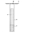
図8は構真柱として用いられるH形鋼45の一例を示す図である。H形鋼45は、地盤51の掘削部53に建て込まれてその天端が地盤面の下方に位置する。H形鋼45の下端部は、構真柱杭57のコンクリートの上端部に埋設される。構真柱杭57の上方の掘削部53は埋戻土58で埋め戻される。
(3. Method for installing H-section steel 45)
FIG. 8 is a view showing an example of an H-
以下、このH形鋼45の建込方法について図9等を参照して説明する。
Hereinafter, a method for installing the H-shaped
本実施形態では、図9(a)に示すように、まず地盤51を鉛直方向に掘削して掘削部53を形成し、構真柱杭57のコンクリートを打設する。そして、H形鋼45を吊り下げるなどして掘削部53内で鉛直方向に配置し、その上端部を地上の架台54で仮支持した状態で建込治具1とH形鋼45を連結する。
In the present embodiment, as shown in FIG. 9A, first, the
連結方法は前記した通りであるが、この際のロッド7やストッパ25の操作は、地盤面に近いロッド7の下部のハンドル11bやストッパ25の下部の突起部31bを持って地上で行うとよい。
The connection method is as described above, but the operation of the
その後、構真柱杭57のコンクリートが固化する前に、図9(b)に示すようにH形鋼45を掘削部53の所定深さまで建て込み、H形鋼45の下端部を構真柱杭57のコンクリートの上端部に埋設する。H形鋼45の天端は地盤面より下方にあるが、建込治具1の一部は地上にあり、高さ調整用プレート37に取付けた固定治具55が地盤面に設けた架台54上に設置される。
After that, before the concrete of the
図10は図9(b)の範囲Bを示す図である。図10に示すように、固定治具55と高さ調整用プレート37とは、高さ調整用プレート37の調整孔39のうち適切なものを選択し、その調整孔39と固定治具55に設けられた図示しない孔の位置を合わせ、これらの孔にボルト61を通し、その先端にナットを締め込むことにより固定される。
FIG. 10 is a diagram showing a range B in FIG. As shown in FIG. 10, as the fixing
これによりH形鋼45の建込深さに合わせて建込治具1を適切な高さで固定することができ、この状態でH形鋼45を保持する。構真柱杭57のコンクリートの固化後、建込治具1とH形鋼45の連結を解除して図9(c)に示すように建込治具1をH形鋼45から取り外す。
Thus, the
建込治具1とH形鋼45の連結の解除方法は前記した通りであるが、この際のストッパ25やロッド7の操作は、ストッパ25の上部の突起部31aやロッド7の上部のハンドル11a(図10参照)を持って地上で行うことができる。
The method of releasing the connection between the
こうして建込治具1の取り外しを行った後、構真柱杭57の上方の掘削部53は図8に示すように埋戻土58で埋め戻す。あるいは流動化処理土などで埋め戻してもよい。取り外した建込治具1は、他のH形鋼45の建て込みに転用することができる。
After removing the
このように、本実施形態では、建込治具1とH形鋼45とを連結するための連結ピン21が、ロッド7の軸周りの回転によって連結用プレート19およびH形鋼45のピン孔23、59に出し入れされるので、ロッド7の操作により建込治具1とH形鋼45との連結およびその解除を確実に行うことができる。
Thus, in this embodiment, the connecting
また本実施形態ではロッド7にハンドル11を設けることにより、ロッド7を容易に操作することができる。ハンドル11は上下に設けられており、H形鋼45を建て込む際、建込治具1とH形鋼45の連結時および連結の解除時の双方において、いずれか適当なハンドル11(連結時は下部のハンドル11b、連結の解除時は上部のハンドル11a)により地上でロッド7の操作を行うことが可能になる。
In this embodiment, the
また本実施形態ではロッド7の回転を防止するためのストッパ25が設けられる。これにより、H形鋼45を建て込む際に意図しないロッド7の回転により連結ピン21が連結用プレート19およびH形鋼45のピン孔23、59から抜け、建込治具1とH形鋼45との連結が解除されてH形鋼45が建込治具1から抜け落ちるのを防止することができる。
In the present embodiment, a
特に本実施形態では、ストッパ25の上端25aによりハンドル11aの先端を本体2側に抑え、ハンドル11aの位置を固定することでロッド7の回転を防止する。またストッパ25の側面の突起部31がストッパ保持部27の側面に設けられた鉤状の溝29に通されることで、ストッパ25の上下動と軸周りの回転によってストッパ25を複数の高さ(図1のように突起部31が直線部29aの最下端にあるときの高さと、図6のように突起部31が折曲部29bに配置されているときの高さ)で固定することが可能になり、ストッパ25によりロッド7の回転が防止された状態とそれが解除された状態とをストッパ25の高さによって切り替えることができる。
In particular, in the present embodiment, the tip end of the
また、ロッド7にはアーム13が設けられ、当該アーム13が連結ピン21を保持するピン保持部15に回転可能に連結されるので、ロッド7の回転をクランク式の機構により連結ピン21の出し入れ運動に好適に変換し、建込治具1とH形鋼45との連結およびその解除をより確実に行うことができる。
The
また本実施形態では、高さ調整用プレート37の複数の調整孔39のうち適切なものを選び、建込治具1を固定するための固定治具55の取付に用いることで、建込治具1をH形鋼45の建込深さに合わせた適切な高さで固定することができる。また建込治具1を転用して複数のH形鋼45を異なる深さで建て込む際にも、各々の深さに合わせて建込治具1を適切な高さで固定することができる。
Moreover, in this embodiment, an appropriate thing is selected from the several adjustment holes 39 of the
しかしながら本発明はこれに限らない。例えば本実施形態では、建込治具1の本体2を、H形鋼45と同様の断面寸法を有するH形鋼としたが、本体2とH形鋼45の断面寸法は同じでなくてもよく、断面寸法の違いをスペーサなどを用いて補うことが可能である。
However, the present invention is not limited to this. For example, in this embodiment, the
例えば図11の例ではH形鋼45のせい(両フランジ47の外側面間の距離)が建込治具1の本体2よりも大きいが、この場合は、締結具43を取り外して挟み込みプレート41を一旦フランジ3から取り外し、当該フランジ3と挟み込みプレート41との間に1または複数枚の板状のスペーサ63(シムプレート)を配置し、挟み込みプレート41とスペーサ63を締結具43によって再度フランジ3に固定する。
For example, in the example of FIG. 11, the H-shaped
スペーサ63の厚みや枚数により挟み込みプレート41同士の離隔をH形鋼45のせいに合わせて調整することができ、挟み込みプレート41によってH形鋼45を適切に挟み込み、H形鋼45の位置ずれを防ぐことができる。また建込治具1を転用してせいが異なる複数のH形鋼45を建て込む際にも、各々のせいに合わせてH形鋼45を適切に挟み込むことができる。
The distance between the sandwiching
ただし、建込治具1を用いて建て込むH形鋼45のせいが一律である場合には、本体2のせいをH形鋼45に合わせて挟み込みプレート41をフランジ3に溶接固定してもよい。あるいは、連結ピン21のみでH形鋼45を安定した状態で連結できるのであれば、挟み込みプレート41を省略することも可能である。
However, if the H-shaped
また、本実施形態では建込治具1の本体2をH形鋼としたが、これに限ることはなく、剛性がH形鋼45と同等の材質であれば断面形状は矩形や円形でも良い。また建込治具1で建て込む鋼材もH形鋼45に限ることはない。これらの断面形状は、建込治具1の本体2と鋼材を連結ピン21により連結できるような組合せであればよい。
In the present embodiment, the
また、本実施形態ではアーム13とピン保持部15からなるクランク式の機構によりロッド7の回転運動を連結ピン21の出し入れ運動に変換したが、変換機構はこれに限らない。例えば回転ギアなどを用いることも可能である。
In the present embodiment, the crank type mechanism including the
また、ロッド7の回転を防止する手段も、前記のストッパ25を用いるものに限らない。建込中にロッド7が回転しなければ他のストッパを用いてもよい。
Further, the means for preventing the rotation of the
また、本実施形態では、高さ調整用プレート37の適切な調整孔39を選んで固定治具55を取付け、これにより建込治具1の固定高さをH形鋼45の建込深さに合わせて調整するが、建込治具1を用いて建て込むH形鋼45の天端の位置が一律であれば、建込治具1のフランジ3の適当な高さに固定治具55を溶接固定してもよい。
Further, in the present embodiment, an
また、本実施形態では構真柱の施工例を説明したが、建込治具1はその他の工事においても適用できる。例えば場所打ちコンクリート杭の芯材や、ソイルセメント壁等の地中連続壁の芯材として鋼材を建て込む際にも適用できる。
Moreover, although the construction example of the construction pillar was demonstrated in this embodiment, the
以上、添付図面を参照しながら、本発明に係る好適な実施形態について説明したが、本発明はかかる例に限定されない。当業者であれば、本願で開示した技術的思想の範疇内において、各種の変更例又は修正例に想到し得ることは明らかであり、それらについても当然に本発明の技術的範囲に属するものと了解される。 The preferred embodiments of the present invention have been described above with reference to the accompanying drawings, but the present invention is not limited to such examples. It will be apparent to those skilled in the art that various changes or modifications can be conceived within the scope of the technical idea disclosed in the present application, and these naturally belong to the technical scope of the present invention. Understood.
1:建込治具
2:本体
7:ロッド
9:ロッド保持部
11、11a、11b:ハンドル
13:アーム
15:ピン保持部
19:連結用プレート
21:連結ピン
23、59:ピン孔
25:ストッパ
27:ストッパ保持部
29:溝
31、31a、31b:突起部
33:ロック部
37:高さ調整用プレート
39:調整孔
41:挟み込みプレート
45:H形鋼
51:地盤
53:掘削部
55:固定治具
57:構真柱杭
58:埋戻土
63:スペーサ
1: Construction jig 2: Body 7: Rod 9:
Claims (6)
柱状の本体と、
前記本体の軸方向に沿って配置されたロッドと、
前記本体の下端部に設けられた、前記鋼材をその間に差し込むための一対の連結用プレートと、
前記ロッドの軸周りの回転により、一対の前記連結用プレートおよびその間に差し込まれた前記鋼材に設けられたピン孔に出し入れされる連結ピンと、
前記ロッドの軸周りの回転を防止するためのストッパと、
を具備し、
前記ロッドから側方に突出するハンドルが、前記ロッドの上下に複数設けられることを特徴とする建込治具。 An erection jig used for erection of the steel material connected to the steel material,
A columnar body,
A rod disposed along the axial direction of the body;
A pair of connecting plates provided at the lower end of the main body for inserting the steel material therebetween;
A connection pin that is inserted into and removed from a pair of the connection plates and a pin hole provided in the steel material inserted between the connection plates by rotation around the axis of the rod;
A stopper for preventing rotation around the axis of the rod;
Comprising
A mounting jig characterized in that a plurality of handles protruding laterally from the rod are provided above and below the rod.
前記突起部は、前記ストッパが通された筒状の保持部の側面に設けられた鉤状の溝に通されることを特徴とする請求項2に記載の建込治具。 The stopper is a rod-like member that can move up and down and rotate around an axis, and has a protrusion on the side surface.
The erection jig according to claim 2, wherein the protrusion is passed through a gutter-like groove provided on a side surface of a cylindrical holding part through which the stopper is passed.
前記アームが前記連結ピンを保持するピン保持部に回転可能に連結されることを特徴とする請求項1から請求項3のいずれかに記載の建込治具。 An arm is provided on the rod;
The erection jig according to any one of claims 1 to 3, wherein the arm is rotatably connected to a pin holding portion that holds the connection pin.
前記プレートに前記本体の軸方向に間隔を空けて複数の孔が設けられたことを特徴とする請求項1から請求項4のいずれかに記載の建込治具。 A plate is attached along the axial direction of the main body,
The mounting jig according to any one of claims 1 to 4, wherein the plate is provided with a plurality of holes at intervals in the axial direction of the main body.
前記本体と前記挟み込みプレートの間に板状のスペーサが1または複数枚配置されたことを特徴とする請求項1から請求項5のいずれかに記載の建込治具。 A pair of sandwiching plates for sandwiching the steel material is provided at the lower end of the main body,
6. The erection jig according to claim 1, wherein one or a plurality of plate-like spacers are arranged between the main body and the sandwiching plate.
Priority Applications (1)
| Application Number | Priority Date | Filing Date | Title |
|---|---|---|---|
| JP2018092893A JP6978378B2 (en) | 2018-05-14 | 2018-05-14 | Built-in jig |
Applications Claiming Priority (1)
| Application Number | Priority Date | Filing Date | Title |
|---|---|---|---|
| JP2018092893A JP6978378B2 (en) | 2018-05-14 | 2018-05-14 | Built-in jig |
Publications (2)
| Publication Number | Publication Date |
|---|---|
| JP2019199687A true JP2019199687A (en) | 2019-11-21 |
| JP6978378B2 JP6978378B2 (en) | 2021-12-08 |
Family
ID=68611849
Family Applications (1)
| Application Number | Title | Priority Date | Filing Date |
|---|---|---|---|
| JP2018092893A Active JP6978378B2 (en) | 2018-05-14 | 2018-05-14 | Built-in jig |
Country Status (1)
| Country | Link |
|---|---|
| JP (1) | JP6978378B2 (en) |
Citations (10)
| Publication number | Priority date | Publication date | Assignee | Title |
|---|---|---|---|---|
| JPS5733621A (en) * | 1980-07-31 | 1982-02-23 | Takenaka Komuten Co Ltd | Method for erecting structure column into pit and device therefor |
| JPH03103330U (en) * | 1990-02-05 | 1991-10-28 | ||
| JPH0497939U (en) * | 1991-01-09 | 1992-08-25 | ||
| JPH055391A (en) * | 1991-06-28 | 1993-01-14 | Kajima Corp | Structure pillar built-in stand |
| JPH0660631U (en) * | 1992-05-13 | 1994-08-23 | 株式会社竹中工務店 | Jig for suspending core material |
| JPH0685439U (en) * | 1993-05-20 | 1994-12-06 | 株式会社竹中工務店 | Auxiliary jig for inserting core material for mountain retaining wall |
| JPH08416U (en) * | 1993-03-31 | 1996-02-27 | 前田建設工業株式会社 | Yatco connecting device for building H-shaped steel piles |
| JP2006207254A (en) * | 2005-01-28 | 2006-08-10 | Toa Harbor Works Co Ltd | Plier steel sheet pile and method of driving steel sheet pile using the same |
| US20160017564A1 (en) * | 2012-02-16 | 2016-01-21 | Trojan Services Limited | Apparatus for securing and aligning an attached post in a pile and a corresponding method |
| JP2017106187A (en) * | 2015-12-08 | 2017-06-15 | 株式会社トーヨーアサノ | Rotary cap, precast pile burying device, and pile foundation structure construction method |
-
2018
- 2018-05-14 JP JP2018092893A patent/JP6978378B2/en active Active
Patent Citations (10)
| Publication number | Priority date | Publication date | Assignee | Title |
|---|---|---|---|---|
| JPS5733621A (en) * | 1980-07-31 | 1982-02-23 | Takenaka Komuten Co Ltd | Method for erecting structure column into pit and device therefor |
| JPH03103330U (en) * | 1990-02-05 | 1991-10-28 | ||
| JPH0497939U (en) * | 1991-01-09 | 1992-08-25 | ||
| JPH055391A (en) * | 1991-06-28 | 1993-01-14 | Kajima Corp | Structure pillar built-in stand |
| JPH0660631U (en) * | 1992-05-13 | 1994-08-23 | 株式会社竹中工務店 | Jig for suspending core material |
| JPH08416U (en) * | 1993-03-31 | 1996-02-27 | 前田建設工業株式会社 | Yatco connecting device for building H-shaped steel piles |
| JPH0685439U (en) * | 1993-05-20 | 1994-12-06 | 株式会社竹中工務店 | Auxiliary jig for inserting core material for mountain retaining wall |
| JP2006207254A (en) * | 2005-01-28 | 2006-08-10 | Toa Harbor Works Co Ltd | Plier steel sheet pile and method of driving steel sheet pile using the same |
| US20160017564A1 (en) * | 2012-02-16 | 2016-01-21 | Trojan Services Limited | Apparatus for securing and aligning an attached post in a pile and a corresponding method |
| JP2017106187A (en) * | 2015-12-08 | 2017-06-15 | 株式会社トーヨーアサノ | Rotary cap, precast pile burying device, and pile foundation structure construction method |
Also Published As
| Publication number | Publication date |
|---|---|
| JP6978378B2 (en) | 2021-12-08 |
Similar Documents
| Publication | Publication Date | Title |
|---|---|---|
| JP6173671B2 (en) | Structural foundation | |
| US10151113B2 (en) | Rebar centralizer for use in a drilled shaft/bore hole | |
| JP2017008543A (en) | Foundation structure | |
| US10584459B2 (en) | Adjustable rebar centralizer for use in a drilled shaft/bore hole | |
| KR101862623B1 (en) | Soil retaining wall using movable pile | |
| JPH0768705B2 (en) | Soil retaining method and its retaining pile | |
| JP5207998B2 (en) | Pile head joint member and pile head joint structure using the same | |
| KR102480876B1 (en) | Structure for reinforcing foundation using steel piles and construction method thereof | |
| JP3171898U (en) | Casing for installing finned steel pipe piles | |
| JP2019199687A (en) | Erection tool | |
| JP6757003B2 (en) | Construction method of double pipe pile and double pipe pile | |
| JP2022114198A (en) | Installation method for spring spacers, reinforcing bar cages and underground piles | |
| JP5204692B2 (en) | Pre-boring H-section steel pile | |
| KR102821801B1 (en) | Guide device used in SCW method And Construction metood usinf thereof | |
| JP2004027727A (en) | Foundation pile and construction method of foundation pile | |
| JP2019210711A (en) | Method for reinforcing existing structure in ground | |
| KR200194424Y1 (en) | Precast retaining wall using high strength micro pile | |
| JP2023009672A (en) | Reversely driven column erecting method and reversely driven column used for the same | |
| JP7768930B2 (en) | Joint structure between piles and superstructure | |
| JP4840297B2 (en) | Construction method of underground structure, underground structure | |
| KR20210098162A (en) | Under ground structure using column steel pipe wall and construction method thereof | |
| JP7301203B1 (en) | Earth retaining device for shallow excavated trenches | |
| JP3325550B2 (en) | Pile construction equipment and pile construction method | |
| JPH1122365A (en) | Construction method of shaft and device therefor | |
| JPH0559215B2 (en) |
Legal Events
| Date | Code | Title | Description |
|---|---|---|---|
| A621 | Written request for application examination |
Free format text: JAPANESE INTERMEDIATE CODE: A621 Effective date: 20201204 |
|
| A977 | Report on retrieval |
Free format text: JAPANESE INTERMEDIATE CODE: A971007 Effective date: 20211008 |
|
| TRDD | Decision of grant or rejection written | ||
| A01 | Written decision to grant a patent or to grant a registration (utility model) |
Free format text: JAPANESE INTERMEDIATE CODE: A01 Effective date: 20211102 |
|
| A61 | First payment of annual fees (during grant procedure) |
Free format text: JAPANESE INTERMEDIATE CODE: A61 Effective date: 20211111 |
|
| R150 | Certificate of patent or registration of utility model |
Ref document number: 6978378 Country of ref document: JP Free format text: JAPANESE INTERMEDIATE CODE: R150 |
|
| R250 | Receipt of annual fees |
Free format text: JAPANESE INTERMEDIATE CODE: R250 |