JP2020002611A - Movable partition device - Google Patents

Movable partition device Download PDF

Info

Publication number
JP2020002611A
JP2020002611A JP2018122716A JP2018122716A JP2020002611A JP 2020002611 A JP2020002611 A JP 2020002611A JP 2018122716 A JP2018122716 A JP 2018122716A JP 2018122716 A JP2018122716 A JP 2018122716A JP 2020002611 A JP2020002611 A JP 2020002611A
Authority
JP
Japan
Prior art keywords
ball
rail
cap
resin receiving
traveling
Prior art date
Legal status (The legal status is an assumption and is not a legal conclusion. Google has not performed a legal analysis and makes no representation as to the accuracy of the status listed.)
Granted
Application number
JP2018122716A
Other languages
Japanese (ja)
Other versions
JP7102066B2 (en
Inventor
隆久 小林
Takahisa Kobayashi
隆久 小林
康彦 宮田
Yasuhiko Miyata
康彦 宮田
恒夫 下村
Tsuneo Shimomura
恒夫 下村
Current Assignee (The listed assignees may be inaccurate. Google has not performed a legal analysis and makes no representation or warranty as to the accuracy of the list.)
Okamura Corp
Original Assignee
Okamura Corp
Priority date (The priority date is an assumption and is not a legal conclusion. Google has not performed a legal analysis and makes no representation as to the accuracy of the date listed.)
Filing date
Publication date
Application filed by Okamura Corp filed Critical Okamura Corp
Priority to JP2018122716A priority Critical patent/JP7102066B2/en
Publication of JP2020002611A publication Critical patent/JP2020002611A/en
Application granted granted Critical
Publication of JP7102066B2 publication Critical patent/JP7102066B2/en
Active legal-status Critical Current
Anticipated expiration legal-status Critical

Links

Images

Landscapes

  • Support Devices For Sliding Doors (AREA)

Abstract

To provide a movable partition device capable of reducing noise and vibration generated when a suspending member moves on a sphere body.SOLUTION: A movable partition device includes a partition panel 2 suspended by suspending members 9, 9 which can travel on travel surfaces 41a, 41a formed on travel rails 4A, 4B, ..., 4G and movable along a travel rail 3 and formed with a crossing portion 5 where the travel surfaces 41a, 41a, ... of the travel rails 4A, 4B, ..., 4G which are prepared in plural intersect each other. The crossing portion 5 is provided with a metallic sphere body 15 and a resin receiving member 11 which has at least a part of a spherical shape complementary to the spherical shape of the sphere body 15 and holds an upper surface of the sphere body 15 in an exposed state.SELECTED DRAWING: Figure 3

Description

本発明は、オフィス、展示ホール、会議場等を所定の区画に仕切って使用するための移動間仕切装置に関する。   The present invention relates to a mobile partition device for partitioning an office, an exhibition hall, a conference hall, and the like into predetermined sections for use.

移動間仕切装置は、天井に設けられた走行レールに形成される走行面上を走行可能な車輪を有する吊支体により吊支され走行レールに沿って移動可能な間仕切パネルを一列に連接して壁面を形成し、オフィス、展示ホール、会議場等の室内空間を所定の区画に仕切る用途で利用されている。また、室内空間におけるレイアウトの自由度を高めるために、複数の走行レールの走行面が互いに交差する交差部を形成し、交差部において間仕切パネルの移動方向を切り替えることにより、間仕切パネルによる壁面の形成位置を変更できるようにした移動間仕切装置がある。   The moving partitioning device includes a partition wall that is supported by a suspension body having wheels that can travel on a traveling surface formed on a traveling rail provided on a ceiling and that is movable along the traveling rail in a row. And is used for partitioning an indoor space such as an office, an exhibition hall, and a conference hall into predetermined sections. Also, in order to increase the degree of freedom of layout in the indoor space, the running surfaces of the plurality of running rails form an intersection where they intersect with each other, and the moving direction of the partition panel is switched at the intersection, thereby forming the wall surface by the partition panel. There is a moving partition device that can change the position.

特許文献1に示される移動間仕切装置は、レール部材(走行レール)に沿って走行可能な吊車(吊支体)により吊支される移動壁(間仕切パネル)と、複数のレール部材を互いに直交させて接続する方向変換部材(走行レールの交差部)を備え、レール部材および方向変換部材には、下方に開口するスリット部を挟んで一対の走行面が形成されている。吊車は、スリット部を介して移動壁に連結される連結杆の上端部を保持する基台部と、基台部の上下に固定された上板および底板と、基台部の各側面に配設され水平軸回りに回転自在な車輪と、から主に構成されている。   The moving partition device disclosed in Patent Literature 1 makes a moving wall (partition panel) suspended by a suspension vehicle (suspension support) that can travel along a rail member (travel rail) and a plurality of rail members orthogonal to each other. The rail member and the direction converting member are formed with a pair of running surfaces with a slit opening downwardly interposed therebetween. The suspension vehicle has a base for holding an upper end of a connecting rod connected to the moving wall through a slit, an upper plate and a bottom plate fixed above and below the base, and a suspension on each side of the base. And a wheel rotatable about a horizontal axis.

また、移動壁を吊支する吊車を一方のレール部材に沿って移動させ、方向変換部材に形成される平面視十字状のスリット部の交差部分を通過させるときに、吊車の車輪がスリット部の交差部分に落ち込むことを防止するために、スリット部の交差部分を形成する走行面の各角部には半球状の凹部がそれぞれ形成され、凹部内に配置されたボール(球体)の上面を露出させた状態でボール保持片によって転動自在に保持することにより、ボールの上面に吊車の底板を乗り上げさせる構造になっている。さらに、ボールと凹部との間に複数の小球を介在させることにより、ボールの上面を吊車が移動する際にボールが転動しやすくなっており、移動壁の移動方向を円滑に切り替えることができる。   Further, when the suspension vehicle that suspends and supports the moving wall is moved along one of the rail members and passes through the intersection of the cross-shaped slits formed in the direction changing member in a plan view, the wheels of the suspension vehicle are moved along the slits. Hemispherical recesses are formed at each corner of the running surface that forms the intersection of the slits to prevent falling into the intersection, and the upper surface of the ball (sphere) disposed in the recess is exposed. In this state, the ball is held by the ball holding piece so as to be able to roll freely, so that the bottom plate of the hanging vehicle rides on the upper surface of the ball. Furthermore, by interposing a plurality of small balls between the ball and the concave portion, the ball easily rolls when the suspension car moves on the upper surface of the ball, and the moving direction of the moving wall can be switched smoothly. it can.

特開2007−23718号公報(第4頁、第6図)JP 2007-23718 A (Page 4, FIG. 6)

しかしながら、特許文献1にあっては、ボールと、レール部材の凹部との間に介在する複数の小球が互いに金属接触することとなるため、吊車がボールに乗り移るときの衝撃により大きな騒音や振動を発生させてしまうという問題があった。   However, in Patent Literature 1, since a plurality of small balls interposed between the ball and the concave portion of the rail member come into metal contact with each other, a large noise or vibration is generated due to an impact when the suspension vehicle moves onto the ball. There was a problem that would generate.

本発明は、このような問題点に着目してなされたもので、吊支体が球体に乗り移るときに発生する騒音や振動を軽減することができる移動間仕切装置を提供することを目的とする。   The present invention has been made in view of such a problem, and an object of the present invention is to provide a moving partition device that can reduce noise and vibration generated when a suspension body moves on a sphere.

前記課題を解決するために、本発明の移動間仕切装置は、
走行レールに形成される走行面上を走行可能な吊支体により吊支され前記走行レールに沿って移動可能な間仕切パネルを備え、複数の前記走行レールの走行面が互いに交差する交差部が形成される移動間仕切装置であって、
前記交差部には、金属の球体と、前記球体の球面と相補的な球面形状を少なくとも一部有し前記球体の上面を露出させた状態で保持する樹脂受け材が設けられていることを特徴としている。
この特徴によれば、交差部において吊支体が球体に乗り移るときに、球体を樹脂受け材の弾性力で受けることにより球体と樹脂受け材との間で衝撃が緩衝されるため、騒音や振動を軽減することができる。
In order to solve the above problems, the moving partitioning device of the present invention is
A partition panel is provided that is suspended by a suspension that can travel on a traveling surface formed on the traveling rail and is movable along the traveling rail, and an intersection is formed in which the traveling surfaces of the plurality of traveling rails intersect each other. Moving partitioning device,
The intersection is provided with a metal sphere and a resin receiving material having at least a part of a spherical shape complementary to the spherical surface of the sphere and holding the spherical body in a state where the upper surface is exposed. And
According to this feature, when the hanging support moves onto the sphere at the intersection, the impact between the sphere and the resin receiving material is buffered by receiving the sphere with the elastic force of the resin receiving material, so that noise and vibration are reduced. Can be reduced.

前記樹脂受け材は、前記球体の中心よりも上方に延びていることを特徴としている。
この特徴によれば、樹脂受け材の上端部により球体の抜け出しを防止することができる。
The resin receiving member extends upward from the center of the sphere.
According to this feature, the spherical body can be prevented from coming off by the upper end portion of the resin receiving material.

前記交差部には、前記樹脂受け材の外面と相補的な形状を有し前記樹脂受け材を保持する凹部が形成されていることを特徴としている。
この特徴によれば、走行面の凹部に樹脂受け材を取り付けることにより、樹脂受け材の外形が保持されるため、樹脂受け材の内面における球面形状の変形を防止することができる。
The intersection is formed with a concave portion having a shape complementary to the outer surface of the resin receiving material and holding the resin receiving material.
According to this feature, since the outer shape of the resin receiving material is maintained by attaching the resin receiving material to the concave portion of the running surface, the deformation of the spherical shape on the inner surface of the resin receiving material can be prevented.

前記樹脂受け材は、上端部から下方に延びるスリットが形成されていることを特徴としている。
この特徴によれば、スリットにより樹脂受け材の上端部を拡開させやすくなるため、球体を樹脂受け材の内部に挿嵌させやすい。
The resin receiving member is characterized in that a slit extending downward from an upper end portion is formed.
According to this feature, the slit makes it easier to expand the upper end portion of the resin receiving material, so that the sphere can be easily inserted into the resin receiving material.

前記樹脂受け材は、上端部が厚肉に形成されることを特徴としている。
この特徴によれば、球体が樹脂受け材の上端部により覆われる範囲を球体の上面近くまで広げることができるため、吊支体が球体の上面に乗り移らせる際の衝撃音を外部へ逃がしにくい。
The resin receiving member is characterized in that the upper end is formed to be thick.
According to this feature, since the range in which the sphere is covered by the upper end portion of the resin receiving material can be extended to near the upper surface of the sphere, it is difficult for the suspension sound to escape to the outside when the suspension support is transferred to the upper surface of the sphere. .

前記樹脂受け材は、上端部から外径側に延びる鍔部が形成されていることを特徴としている。
この特徴によれば、樹脂受け材が鍔部により回り止めされるため、球体と樹脂受け材との共回りを防止することができる。
The resin receiving member is characterized in that a flange portion extending from the upper end portion to the outer diameter side is formed.
According to this feature, since the resin receiving material is prevented from rotating by the flange portion, co-rotation of the sphere and the resin receiving material can be prevented.

前記凹部の底部には、前記交差部の外部に連通する貫通孔が形成されていることを特徴としている。
この特徴によれば、交差部の外部から貫通孔を介して凹部に取り付けられた樹脂受け材にアクセスできるため、樹脂受け材を下方から押し上げて球体と一緒に取外すことができ、メンテナンス作業が容易である。
A through hole communicating with the outside of the intersection is formed at the bottom of the recess.
According to this feature, since the resin receiving material attached to the concave portion can be accessed from the outside of the intersection through the through hole, the resin receiving material can be pushed up from below and removed together with the sphere, thereby facilitating maintenance work. It is.

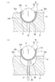
本発明の実施例における移動間仕切装置を示す斜視図である。1 is a perspective view showing a moving partition device according to an embodiment of the present invention. 交差部と吊支体とを示す上断面図である。It is an upper sectional view which shows an intersection part and a hanging support body. 図1におけるA−A矢視図である。FIG. 2 is a view as viewed in the direction of arrows AA in FIG. 1. 交差部を構成する接続部材を示す正面図である。It is a front view which shows the connection member which comprises an intersection part. 球体と樹脂受け材とを示す分解斜視図である。It is a disassembled perspective view which shows a sphere and a resin receiving material. (a)は、凹部に挿嵌された球体および樹脂受け材を示す側断面図であり、(b)は、凹部から取出された球体および樹脂受け材を示す側断面図である。(A) is a side sectional view showing a sphere and a resin receiving member inserted into a concave portion, and (b) is a side sectional view showing a sphere and a resin receiving member taken out from the concave portion. (a)〜(c)は、交差部を移動する吊支体を示す模式図である。(A)-(c) is a schematic diagram which shows the hanging support body which moves an intersection.

本発明に係る移動間仕切装置を実施するための形態を実施例に基づいて以下に説明する。   An embodiment for implementing a moving partition device according to the present invention will be described below based on an embodiment.

実施例に係る移動間仕切装置につき、図1から図7を参照して説明する。以下、図1の紙面左下側を移動間仕切装置の正面側(前方側)とし、その前方側から見たときの上下左右前後方向を基準として説明する。   A moving partition device according to an embodiment will be described with reference to FIGS. Hereinafter, the lower left side of the sheet of FIG. 1 will be referred to as the front side (front side) of the moving partitioning device, and the description will be made with reference to the up, down, left, right, front and rear directions as viewed from the front side.

本実施例の移動間仕切装置1は、図1に示されるように、天井Rに設けられるレールユニット3から吊支部材9,9により吊支され、該レールユニット3に沿って移動可能な複数の間仕切パネル2,2,…を当該間仕切パネル2の幅方向へ直列に連接して壁面を形成し、オフィス、展示ホール、会議場等の室内空間を所定の区画に仕切る用途で使用されるものである。   As shown in FIG. 1, a plurality of movable partitioning devices 1 of this embodiment are suspended from rail units 3 provided on a ceiling R by suspension members 9, 9 and can move along the rail units 3. The partition panels 2, 2, ... are connected in series in the width direction of the partition panel 2 to form a wall surface, and are used for partitioning an interior space of an office, an exhibition hall, a conference hall, or the like into predetermined sections. is there.

図1を参照して、間仕切パネル2は、正面視略長方形状のパネル本体2a、パネル本体2aの上端部に取付けられる吊支部材9,9、から主に構成されている。図2に示されるように、吊支部材9は、上面視正方形状に形成されており、本体部95と、本体部95の前後左右の側端部に配置された軸によって略水平軸回りに回転可能に軸支される4つの走行ローラ90A,90B,90C,90Dと、本体部95の上方側の各角部に配置された軸によって略垂直軸周りに回転可能に軸支される4つのガイドローラ91A,91B,91C,91Dと、本体部95の上面視略中央に設けられ下方に延出し間仕切パネル2の上端部に連結される棒状の連結杆92とから主に構成されている。   Referring to FIG. 1, the partition panel 2 mainly includes a panel main body 2a having a substantially rectangular shape in a front view, and suspension members 9, 9 attached to an upper end portion of the panel main body 2a. As shown in FIG. 2, the suspension support member 9 is formed in a square shape in a top view, and is formed around a substantially horizontal axis by a main body 95 and axes arranged at front, rear, left, and right side ends of the main body 95. Four running rollers 90A, 90B, 90C, 90D rotatably supported and four rotatable shafts rotatably about a substantially vertical axis by shafts disposed at the upper corners of the main body 95. It mainly comprises guide rollers 91A, 91B, 91C, 91D, and a rod-like connecting rod 92 which is provided substantially at the center of the main body 95 in a top view and extends downward and is connected to the upper end of the partition panel 2.

図3を参照して、本体部95は、ガイドローラ91A,91B,91C,91Dが軸支されている板状の上板95a、板状の底板95b、走行ローラ90A,90B,90C,90Dが軸支されている外郭矩形状の走行ローラ支持部95cから主に構成されており、走行ローラ支持部95cは、上板95aと底板95bとの上下方向のスペーサとして機能する。また、上板95aおよび底板95bには、前後左右の側端部の略中央部に、上板95aまたは底板95bの上面視略中央側へ略長方形状に凹む切欠き部が形成されており、この切欠き部内に走行ローラ90A,90B,90C,90Dが配置されている。   Referring to FIG. 3, main body portion 95 includes a plate-shaped upper plate 95a on which guide rollers 91A, 91B, 91C, and 91D are pivotally supported, a plate-shaped bottom plate 95b, and traveling rollers 90A, 90B, 90C, and 90D. It is mainly composed of an outer rectangular traveling roller supporting portion 95c that is pivotally supported, and the traveling roller supporting portion 95c functions as a vertical spacer between the upper plate 95a and the bottom plate 95b. In addition, the upper plate 95a and the bottom plate 95b are provided with cutouts that are recessed in a substantially rectangular shape substantially at the center of the upper plate 95a or the bottom plate 95b when viewed from above, substantially at the center of the front, rear, left, and right side ends. The running rollers 90A, 90B, 90C, 90D are arranged in the notch.

図3を参照して、走行ローラ支持部95cに軸支された走行ローラ90A,90B,90C,90Dの上端は、本体部95の上板95aから上方へ突出している。同様に下端は底板95bから下方へ突出している。尚、本実施例において、上方と下方への突出量は同じとなっているものの、各突出量が異なっていてもよく、限定されるものではない。   Referring to FIG. 3, the upper ends of traveling rollers 90A, 90B, 90C, and 90D supported by traveling roller support 95c project upward from upper plate 95a of main body 95. Similarly, the lower end protrudes downward from the bottom plate 95b. In the present embodiment, although the upward and downward protrusion amounts are the same, each protrusion amount may be different and is not limited.

次に、レールユニット3について説明する。図1に示されるように、レールユニット3は、左右方向に延びる略直線状の横レール30、横レール30と略直交する左右一対の縦レール31,32を備え、各レール30,31,32は、7本のレール部材4A,4B,…,4Gが2つの接続部材5A,5B(交差部)に接続されることにより形成されている。   Next, the rail unit 3 will be described. As shown in FIG. 1, the rail unit 3 includes a substantially linear horizontal rail 30 extending in the left-right direction, and a pair of left and right vertical rails 31 and 32 substantially orthogonal to the horizontal rail 30. Are formed by connecting seven rail members 4A, 4B,..., 4G to two connecting members 5A, 5B (intersections).

詳しくは、横レール30は、右から左に向かって順に、レール部材4B、接続部材5A、レール部材4D、接続部材5B、レール部材4Fから構成され、右側の縦レール31は、前から後に向かって順に、レール部材4A、接続部材5A、レール部材4Cから構成され、左側の縦レール32は、前から後に向かって順に、レール部材4G、接続部材5B、レール部材4Eから構成されている。   Specifically, the horizontal rail 30 includes a rail member 4B, a connection member 5A, a rail member 4D, a connection member 5B, and a rail member 4F in order from right to left, and the right vertical rail 31 faces from front to back. The vertical rail 32 on the left side includes a rail member 4G, a connection member 5B, and a rail member 4E in order from front to rear.

次いで、レール部材4Aについて説明する。尚、他のレール部材4B,4C,…,4Gについては、レール部材4Aと略同一構成であるため、以降の説明において、説明を省略または簡略化する。   Next, the rail member 4A will be described. Since the other rail members 4B, 4C,..., 4G have substantially the same configuration as the rail member 4A, the description thereof will be omitted or simplified in the following description.

図2,図3を参照して、レール部材4Aは、金属の押出し成形により正面視下向きC字状のチャンネル部材であって(図1,図3参照)、下端部略中央に形成された開口部40を挟んで互いの走行面41aが同じ平面上に形成された一対のレール部41,41を有している(図2参照)。また、レール部材4Aの上方側の天井壁の内側には左右一対のガイド溝43が形成されており、吊支部材9のガイドローラ91A,91B,91C,91Dを遊嵌可能となっている(図3参照)。   Referring to FIGS. 2 and 3, rail member 4A is a downwardly facing C-shaped channel member formed by extrusion of metal (see FIGS. 1 and 3), and an opening formed substantially at the center of the lower end. A pair of rail portions 41, 41 are formed on the same plane with their running surfaces 41a sandwiching the portion 40 (see FIG. 2). A pair of left and right guide grooves 43 is formed inside the ceiling wall on the upper side of the rail member 4A, and the guide rollers 91A, 91B, 91C, 91D of the suspension support member 9 can be loosely fitted ( (See FIG. 3).

図3に示されるように、レール部材4Aの開口部40は、連結杆92を挿通可能に形成されている。   As shown in FIG. 3, the opening 40 of the rail member 4A is formed so that the connecting rod 92 can be inserted therethrough.

次いで、右側の接続部材5Aについて説明する。左側の接続部材5Bについては、レール部材4Aと略同一構成であるため、以降の説明において、説明を省略または簡略化する。   Next, the right connection member 5A will be described. The connection member 5B on the left has substantially the same configuration as the rail member 4A, and therefore, description thereof will be omitted or simplified in the following description.

図1〜図4を参照して、接続部材5Aは、上方に設けられ矩形板状の天井板52と、天井板52の4つの角部からそれぞれ下方に延びる角支柱56,56,56,56(図2〜図4参照)と、各角支柱56の下端に固定された4つの矩形板状のレール板51,51,51,51(図2〜図4参照)とから構成されており、左右または前後方向に隣接するレール板51,51は、左右または前後方向に一定距離離間しており、レール板51,51,51,51の間に下面視前後左右に略十字状に開口する開口部50が形成されている。この開口部50の幅は連結杆92を挿通可能に形成されている(図3参照)。   Referring to FIGS. 1 to 4, connection member 5A is provided with a rectangular plate-shaped ceiling plate 52 provided at an upper portion, and angular posts 56, 56, 56, 56 extending downward from four corners of ceiling plate 52, respectively. (See FIGS. 2 to 4) and four rectangular plate-shaped rail plates 51, 51, 51, 51 (see FIGS. 2 to 4) fixed to the lower end of each of the angular supports 56. The rail plates 51, 51 adjacent to each other in the left-right or front-rear direction are spaced apart by a predetermined distance in the left-right or front-rear direction, and open between the rail plates 51, 51, 51, 51 in a substantially cross shape in front-rear, front-rear, left-right directions. A part 50 is formed. The width of the opening 50 is formed so that the connecting rod 92 can be inserted therein (see FIG. 3).

また、図3に示されるように、開口部50の前後方向へ延びる直線部は、接続部材5Aにレール部材4Aが接続された状態において、レール部材4Aの開口部40と連通する。   As shown in FIG. 3, the straight portion extending in the front-rear direction of the opening 50 communicates with the opening 40 of the rail member 4A when the rail member 4A is connected to the connection member 5A.

図2,図3を参照して、左右または前後方向へ隣接する角支柱56,56間の離間寸法は、吊支部材9の前後寸法または左右寸法よりも長寸となっている。また、角支柱56,56,56,56は、天井板52とレール板51,51,51,51とのスペーサとして機能しており、天井板52とレール板51,51,51,51との離間寸法が、走行ローラ90A,90B,90C,90Dの上下寸法よりも長寸となっている(図3参照)。これらにより、左右または前後方向へ隣接する一対の角支柱56,56間および天井板52とレール板51,51,51,51との間を吊支部材9が通過可能となっている。   Referring to FIG. 2 and FIG. 3, the distance between the adjacent rectangular pillars 56 in the left-right or front-back direction is longer than the front-back dimension or the left-right dimension of the suspension support member 9. The square columns 56, 56, 56, 56 function as spacers between the ceiling plate 52 and the rail plates 51, 51, 51, 51, and serve as spacers between the ceiling plate 52 and the rail plates 51, 51, 51, 51. The separation dimension is longer than the vertical dimension of the running rollers 90A, 90B, 90C, 90D (see FIG. 3). Thus, the suspension support member 9 can pass between a pair of adjacent square columns 56 and 56 in the left-right or front-rear direction and between the ceiling plate 52 and the rail plates 51, 51, 51, 51.

図3,4を参照して、天井板52の下端部には、下方から上方へ断面視略長方形状に凹む左右一対のガイド溝53,53が形成されており、左右一対のガイド溝53,53は互いに略平行に天井板52の前後方向に亘って延設されている。また、直接の図示は省略するが、左右一対のガイド溝53,53と略同一形状であり、左右一対のガイド溝53,53と略直交する前後一対のガイド溝53,53も形成されている。各ガイド溝53,53,53,53は、吊支部材9のガイドローラ91A,91B,91C,91Dを遊嵌可能となっている(図3参照)。   Referring to FIGS. 3 and 4, a pair of left and right guide grooves 53, 53 is formed at the lower end of the ceiling plate 52, recessed in a substantially rectangular shape in cross section from below to above. Reference numerals 53 extend substantially in parallel with each other in the front-rear direction of the ceiling plate 52. Although not shown directly, the pair of guide grooves 53 has substantially the same shape as the pair of left and right guide grooves 53, and a pair of front and rear guide grooves 53, 53 substantially orthogonal to the pair of left and right guide grooves 53, 53 are also formed. . Each guide groove 53, 53, 53, 53 is capable of loosely fitting a guide roller 91A, 91B, 91C, 91D of the suspension support member 9 (see FIG. 3).

また、図3に示されるように、左右一対のガイド溝53,53は、接続部材5Aにレール部材4Aが接続された状態において、レール部材4Aのガイド溝43,43と連通する。   As shown in FIG. 3, the pair of left and right guide grooves 53 communicate with the guide grooves 43 of the rail member 4A when the rail member 4A is connected to the connection member 5A.

図2〜図4に示されるように、レール板51は、走行面51aを備え、走行面51aは、上面視略L字の平面状に形成されている(図2参照)。これにより、接続部材5Aでは、横レール30に沿って延びる走行面51a,51a,51a,51aと、縦レール31に沿って延びる走行面51a,51a,51a,51aと、が交差している(図2参照)。また、前端部側の走行面51a,51aは、接続部材5Aにレール部材4Aが接続された状態において、レール部材4Aの走行面41a,41aと略同一面を成す(図3参照)。   As shown in FIGS. 2 to 4, the rail plate 51 includes a running surface 51 a, and the running surface 51 a is formed in a substantially L-shaped planar shape when viewed from above (see FIG. 2). Thus, in the connecting member 5A, the running surfaces 51a, 51a, 51a, 51a extending along the horizontal rail 30 and the running surfaces 51a, 51a, 51a, 51a extending along the vertical rail 31 intersect ( (See FIG. 2). Also, the running surfaces 51a, 51a on the front end side form substantially the same plane as the running surfaces 41a, 41a of the rail member 4A when the rail member 4A is connected to the connecting member 5A (see FIG. 3).

また、図2,図4に示されるように、レール板51は、接続部材5Aの上面視中央部側に位置する角部に(図2参照)、走行面51aから下方へ半球状に凹む凹部54、凹部54の下端部からレール板51の下端(外部)へ貫通する貫通孔55(図4参照)が形成されており、凹部54は、後述するボールユニット10のキャップ11の外面11bと相補的な形状を成しており、ボールユニット10を挿嵌可能となっている(図4,図6参照)。尚、凹部54は、ボールユニット10を挿嵌可能であればよく、従来のように、凹部54に対して精密研磨や焼入れ等の加工を行う必要がないため、製造コストを抑えることができる。   As shown in FIGS. 2 and 4, the rail plate 51 has a concave portion which is hemispherically recessed downward from the running surface 51 a at a corner portion (see FIG. 2) located on the center side of the connection member 5 </ b> A when viewed from above. 54, a through hole 55 (see FIG. 4) penetrating from the lower end of the recess 54 to the lower end (outside) of the rail plate 51, and the recess 54 is complementary to an outer surface 11b of the cap 11 of the ball unit 10 described later. The ball unit 10 can be inserted (see FIGS. 4 and 6). The concave portion 54 only needs to be able to insert the ball unit 10, and there is no need to perform processing such as precision polishing or quenching on the concave portion 54 as in the related art, so that the manufacturing cost can be reduced.

次に、レール板51の凹部54へ挿嵌されるボールユニット10について説明する。図5,図6を参照して、ボールユニット10は、樹脂の射出形成により一体形成され摩擦係数が小さく内部が中空な椀状のキャップ11(樹脂受け材)に、球体に形成された金属製のボール15を挿嵌することにより構成されている。尚、ボール15の受け構造であるキャップ11は一体成形できることから、生産性が良く、製造コストを抑えることができる。   Next, the ball unit 10 inserted into the concave portion 54 of the rail plate 51 will be described. Referring to FIGS. 5 and 6, a ball unit 10 is integrally formed by injection molding of a resin, has a small friction coefficient, and has a hollow inner cup-shaped cap 11 (resin receiving material). The ball 15 is inserted. In addition, since the cap 11 which is the receiving structure of the ball 15 can be integrally formed, the productivity is good and the manufacturing cost can be suppressed.

図5,図6に示されるように、キャップ11は、略同一の板厚で半球板状に形成された半球部12(図6参照)、上面視において略六等配に配置された帯状部13(樹脂受け材の上端部)(図5参照)を備え、隣り合う帯状部13,13の間にスリット14が形成されている。キャップ11の内面11aは、ボール15の球面と相補的な連続する球面形状に形成されている。   As shown in FIGS. 5 and 6, the cap 11 has a hemispherical portion 12 (see FIG. 6) formed in a hemispherical plate shape with substantially the same plate thickness, and a band-like portion arranged in a substantially hexagonal arrangement when viewed from above. 13 (the upper end portion of the resin receiving member) (see FIG. 5), and a slit 14 is formed between the adjacent belt-like portions 13, 13. The inner surface 11 a of the cap 11 is formed in a continuous spherical shape complementary to the spherical surface of the ball 15.

また、キャップ11の内面11aの下端から帯状部13の上端部までの略垂直方向の内寸は、ボール15の最大径である直径よりも短寸かつ半径よりも長寸に形成されており、キャップ11内に挿嵌されたボール15の上端部はキャップ11から露出する。   The substantially vertical inner dimension from the lower end of the inner surface 11a of the cap 11 to the upper end of the band-shaped portion 13 is formed to be shorter than the maximum diameter of the ball 15 and longer than the radius, The upper end of the ball 15 inserted into the cap 11 is exposed from the cap 11.

帯状部13は、半球部12の上端から略同じ肉厚で略垂直上方へ延びるとともに、上端部において内径側および外径側へ突出し肉厚が厚くなる形状となっている。詳しくは、図6を参照して、断面視において、半球部12の外周面から略垂直上方へ直線状に延びる外径側下方垂直面、外径側下方垂直面の上端部から外径方向かつ上方へ傾斜して直線状に延びる外径側下方傾斜面、外径側下方傾斜面の上端部から略垂直上方へ直線状に延びる外径側上方垂直面、外径側上方垂直面の上端部から内径方向かつ上方へ傾斜して直線状に延びる外径側上方傾斜面、外径側上方傾斜面の上端部から内径方向かつ下方へ傾斜して直線状に延びる内径側上方傾斜面、内径側上方傾斜面の下端部から外径方向且つ下方へ湾曲して延びる内径側下方傾斜面を備え、内径側下方傾斜面は、半球部12の内周面と連続する、キャップ11の内面11aの一部である。また、キャップ11の外面11bは、半球部12の外周面に帯状部13の外径側下方垂直面が連続しており、外輪郭が側面視U字状に形成されている。   The belt-like portion 13 extends substantially vertically upward with substantially the same thickness from the upper end of the hemispherical portion 12, and has a shape that protrudes toward the inner diameter side and the outer diameter side at the upper end portion and becomes thicker. Specifically, referring to FIG. 6, in a sectional view, the outer diameter side lower vertical surface linearly extending substantially vertically upward from the outer peripheral surface of the hemispherical portion 12, the outer diameter side lower vertical surface from the upper end of the outer diameter lower vertical surface, and An outer-diameter-side lower inclined surface that linearly extends upward and straight, an outer-diameter-side upper vertical surface that extends linearly substantially vertically upward from an upper end of the outer-diameter-side lower inclined surface, and an upper-end portion of the outer-diameter-side upper vertical surface An outer-diameter-side upper inclined surface that linearly inclines upward and inward from the inner-diameter direction, an inner-diameter-side upper inclined surface that linearly inclines in an inner-diameter direction and downwardly from the upper end of the outer-diameter-side upper inclined surface, An inner diameter-side lower inclined surface that extends outward and in a curved manner from the lower end of the upper inclined surface is formed on the inner surface 11 a of the cap 11, which is continuous with the inner peripheral surface of the hemispherical portion 12. Department. In addition, the outer surface 11b of the cap 11 has the outer diameter side lower vertical surface of the band portion 13 continuous with the outer peripheral surface of the hemispherical portion 12, and the outer contour is formed in a U-shape in side view.

また、帯状部13の上端部には、上述した、外径側下方傾斜面、外径側上方垂直面、および外径側上方傾斜面の一部から成り、外径側下方垂直面から外径側へ突出した鍔部13aが形成されている。   The upper end of the band-shaped portion 13 includes the above-described outer diameter side lower inclined surface, outer diameter side upper vertical surface, and part of the outer diameter side upper inclined surface, and has an outer diameter from the outer diameter side lower vertical surface. A flange 13a protruding to the side is formed.

次に、キャップ11へのボール15の着脱について説明する。図5を参照して、帯状部13の内径側上方傾斜面上に載置したボール15を半球部12側へと押し込むことで、ボール15をキャップ11内へ挿嵌することができる。詳しくは、帯状部13は、略六等配に分割され、外径方向へ弾性変形可能となっており、押し込まれるボール15によって外径側へと押し広げられて拡開し、対向する帯状部13,13間の水平方向の内寸が一時的に広がるため、ボール15の挿嵌が容易となっている。   Next, attachment and detachment of the ball 15 to and from the cap 11 will be described. Referring to FIG. 5, by pushing ball 15 placed on the upper inclined surface on the inner diameter side of belt-shaped portion 13 toward hemispherical portion 12, ball 15 can be inserted into cap 11. More specifically, the belt-shaped portion 13 is divided into approximately six equally distributed portions, and is elastically deformable in the outer diameter direction. Since the horizontal inner dimension between 13 and 13 is temporarily widened, the ball 15 can be easily inserted.

また、ボール15がキャップ11内に押し込むと、帯状部13は弾性変形して径方向に拡がり、その後ボール15の最大径の部分が、内径側上方傾斜面および内径側下方傾斜面から成る内径側の突出部よりも下方に位置することにより、キャップ11の帯状部13の弾性変形が収まり、キャップ11の内面11aをボール15の球面に密着させてボール15をキャップ11内に挿嵌することができる。   When the ball 15 is pushed into the cap 11, the band-shaped portion 13 elastically deforms and expands in the radial direction. Thereafter, the portion of the ball 15 having the maximum diameter is formed by the inner diameter side upper inclined surface and the inner diameter side lower inclined surface. , The elastic deformation of the band-shaped portion 13 of the cap 11 is stopped, and the inner surface 11 a of the cap 11 is brought into close contact with the spherical surface of the ball 15 to insert the ball 15 into the cap 11. it can.

ボール15がキャップ11内に挿嵌された状態について詳しくは、対向する帯状部13,13の内径側下方傾斜面間の水平方向間の内寸は、ボール15の最大径よりも短寸であることから、ボール15の抜け出しを防止して、保持することができる。   For details on the state in which the ball 15 is inserted into the cap 11, the inner dimension in the horizontal direction between the inner-diameter-side lower inclined surfaces of the opposing strips 13, 13 is shorter than the maximum diameter of the ball 15. Therefore, the ball 15 can be prevented from coming off and held.

また、キャップ11内からボール15を取出すには、帯状部13を外径方向へ弾性変形させ内径方向の寸法を一時的に広げることで取出すことができる。このように、キャップ11にボール15が挿嵌された状態では帯状部13がボール15を把持状態に保持しているため、意図せずボール15がキャップ11から抜出すことを防止している。   Further, in order to take out the ball 15 from the inside of the cap 11, it is possible to take out the ball 13 by elastically deforming the belt-like portion 13 in the outer diameter direction and temporarily expanding the dimension in the inner diameter direction. As described above, when the ball 15 is inserted into the cap 11, the band-shaped portion 13 holds the ball 15 in a gripped state, thereby preventing the ball 15 from being unintentionally pulled out of the cap 11.

次に、接続部材5Aの凹部54へのボールユニット10の着脱について説明する。図6(a)を参照して、ボールユニット10を凹部54へ差し込み、キャップ11の各鍔部13aの下端部を接続部材5Aの走行面51aに対して円周状に当接させることで、位置決めを成した状態でボールユニット10を凹部54へ容易に挿嵌することができる。すなわち、鍔部13aによって、ボールユニット10が傾いて挿嵌されることを防止することができる。   Next, attachment and detachment of the ball unit 10 to and from the recess 54 of the connection member 5A will be described. 6A, the ball unit 10 is inserted into the concave portion 54, and the lower end of each flange 13a of the cap 11 is circumferentially abutted against the running surface 51a of the connecting member 5A. The ball unit 10 can be easily inserted into the concave portion 54 in a state where the positioning is performed. That is, the flange 13a can prevent the ball unit 10 from being inserted obliquely.

また、図6(a)に示されるように、凹部54に装着された状態において、鍔部13aは走行面51aよりも上方へ突出することから、挿嵌作業の開始から完了まで鍔部13aを把持して作業することができるため、挿嵌作業が容易であるとともに、位置決めも安定し易い。   Further, as shown in FIG. 6 (a), when the flange 13a is mounted in the recess 54, the flange 13a protrudes above the running surface 51a. Since the work can be performed while being held, the insertion work is easy, and the positioning is easily stabilized.

図2,図3を参照して、左右または前後方向へ隣接するボールユニット10,10の外端間の寸法は、左右一対の走行ローラ90B,90Dまたは前後一対の走行ローラ90A,90Cの内端間の寸法よりも短寸に配置されており、走行ローラ90A,90B,90C,90Dはボールユニット10と接触することなくレール板51の走行面51aを走行可能となっている。   2 and 3, the distance between the outer ends of ball units 10, 10 adjacent in the left-right or front-rear direction is the inner end of a pair of left-right running rollers 90B, 90D or a pair of front-rear running rollers 90A, 90C. It is arranged shorter than the distance between them, and the running rollers 90A, 90B, 90C, 90D can run on the running surface 51a of the rail plate 51 without contacting the ball unit 10.

また、図3を参照して、ボールユニット10が凹部54に装着された状態における、レール板51の走行面51aからのボール15の突出寸法は、走行ローラ90A,90B,90C,90Dの下端が本体部95の底板95bから下方に突出する寸法と略同一寸法である。   Referring to FIG. 3, when the ball unit 10 is mounted in the concave portion 54, the projecting dimension of the ball 15 from the running surface 51 a of the rail plate 51 is such that the lower ends of the running rollers 90 A, 90 B, 90 C, and 90 D are The dimensions are substantially the same as the dimensions protruding downward from the bottom plate 95b of the main body 95.

また、凹部54に挿嵌されたボールユニット10は、キャップ11が鍔部13aにより回り止めされるため、ボール15とキャップ11との共回りを防止することができる。加えて、凹部54は、外輪郭が側面視U字状に形成されたキャップ11の外面11bと相補的な形状を成しており、挿嵌されたキャップ11の外面11bと面当接していることから、キャップ11が水平軸周りに回動することが防止されている。   Further, since the cap 11 is prevented from rotating by the flange 13a, the ball unit 10 inserted into the recess 54 can prevent the ball 15 and the cap 11 from rotating together. In addition, the concave portion 54 has a shape complementary to the outer surface 11b of the cap 11 whose outer contour is formed in a U-shape in side view, and is in surface contact with the outer surface 11b of the inserted cap 11. Therefore, the cap 11 is prevented from rotating around the horizontal axis.

また、凹部54は、キャップ11の外面11bと相補的な形状を成しており、挿嵌されたキャップ11の外面11bと面当接していることから、キャップ11の外形が凹部54によって保持されるため、キャップ11の内面11aにおける球面形状の変形を防止することができる。同様に、帯状部13の外径方向への弾性変形も防止することができる。   Further, the concave portion 54 has a shape complementary to the outer surface 11b of the cap 11 and is in surface contact with the outer surface 11b of the inserted cap 11, so that the outer shape of the cap 11 is held by the concave portion 54. Therefore, deformation of the spherical shape on the inner surface 11a of the cap 11 can be prevented. Similarly, elastic deformation of the belt-shaped portion 13 in the outer radial direction can be prevented.

図6(b)に示されるように、ボールユニット10を凹部54から取出す際には、接続部材5Aの貫通孔55の下方から棒6を差し入れ、ボールユニット10を下から押し上げることによって簡単に取出すことができる。これにより、メンテナンス作業が容易である。   As shown in FIG. 6B, when removing the ball unit 10 from the concave portion 54, the ball unit 10 is easily removed by inserting the rod 6 from below the through hole 55 of the connecting member 5A and pushing up the ball unit 10 from below. be able to. Thereby, maintenance work is easy.

また、図3に示されるように、キャップ11の外寸は、各レール部材4A,4B,…,4Gの開口部40や接続部材5A,5Bの開口部50の幅より短寸であるため、ボールユニット10を開口部40または開口部50を通じて取り出すことができるため、メンテナンスや修理が容易である。   As shown in FIG. 3, the outer dimension of the cap 11 is smaller than the width of the opening 40 of each of the rail members 4A, 4B,..., 4G and the width of the opening 50 of the connecting members 5A, 5B. Since the ball unit 10 can be taken out through the opening 40 or the opening 50, maintenance and repair are easy.

尚、上述したように、ボールユニット10が凹部54に挿嵌された状態において、鍔部13aを把持することが容易であるため、この鍔部13aを把持して凹部54からボールユニット10を取出してもよい。   As described above, when the ball unit 10 is inserted into the concave portion 54, it is easy to grip the flange portion 13a. Therefore, the user grips the flange portion 13a and removes the ball unit 10 from the concave portion 54. You may.

次に、吊支部材9の移動について、横レール30に沿ってレール部材4Bから接続部材5Aを経由してレール部材4Dへ移動する一例に基づいて説明する。尚、重複する説明については、省略または簡略化する。   Next, the movement of the suspension member 9 will be described based on an example in which the suspension member 9 moves from the rail member 4B to the rail member 4D via the connection member 5A along the horizontal rail 30. In addition, overlapping description will be omitted or simplified.

図2を参照して、吊支部材9は、前後一対の走行ローラ90A,90Cがレール部材4Bの走行面41a,41a上に載置されることによって、レール部材4Bに吊支されており、間仕切パネル2(図1参照)を紙面左方向へ押動させることにより、走行ローラ90A,90Cが走行面41a,41a上を転動して、横レール30に沿って左側へと移動する。   With reference to FIG. 2, the suspension member 9 is suspended from the rail member 4B by a pair of front and rear traveling rollers 90A, 90C placed on the traveling surfaces 41a, 41a of the rail member 4B. By pushing the partition panel 2 (see FIG. 1) to the left in the drawing, the traveling rollers 90A, 90C roll on the traveling surfaces 41a, 41a and move leftward along the horizontal rail 30.

このとき、左右一対の走行ローラ90B,90Dは、レール部材4Bの開口部40上に位置しているため、移動の妨げとなることが防止されている。   At this time, since the pair of left and right traveling rollers 90B and 90D are located on the opening 40 of the rail member 4B, they are prevented from hindering movement.

また、ガイドローラ91A,91B,91C,91Dがレール部材4Bのガイド溝43,43(図3参照)の内壁に接触することで、吊支部材9の移動が案内されるとともに、間仕切パネル2の揺れや傾きが防止されている。   In addition, the guide rollers 91A, 91B, 91C, and 91D come into contact with the inner walls of the guide grooves 43, 43 (see FIG. 3) of the rail member 4B, thereby guiding the movement of the suspension support member 9 and also causing the partition panel 2 to move. Shaking and tilting are prevented.

左側へと移動する吊支部材9は、図7(a)に示されるように、前後一対の走行ローラ90A,90Cがレール部材4Bの走行面41a,41aから接続部材5Aの右側端部の前後一対の走行面51a,51a上へと乗り移り、走行面51a,51a上をさらに左側へと移動されることによって、図7(b)に示されるように、吊支部材9の本体部95の底板95bが、接続部材5Aの右側端部に配置された前後一対のボールユニット10,10のボール15,15の上面と接触する。尚、説明の都合上、図7では前方側の角支柱56,56の図示を省略している。   As shown in FIG. 7A, the suspension support member 9 that moves to the left has a pair of front and rear running rollers 90A and 90C that are moved from the running surfaces 41a and 41a of the rail member 4B to the front and rear of the right end of the connecting member 5A. As shown in FIG. 7B, the bottom plate of the main body 95 of the suspension member 9 is moved to the left side on the pair of running surfaces 51a, 51a and further on the running surfaces 51a, 51a. 95b is in contact with the upper surfaces of the balls 15, 15 of the pair of front and rear ball units 10, 10 arranged at the right end of the connection member 5A. Note that, for convenience of explanation, illustration of the front-side rectangular columns 56, 56 is omitted in FIG.

このとき、吊支部材9とボール15との間の接触による衝撃をキャップ11の弾性力で受けることによりボール15とキャップ11との間で衝撃が緩衝されるため、この接触によって発生する吊支部材9やボール15の振動が吸収される。同様に、ボール15とキャップ11との間で発生する衝撃についてもキャップ11の弾性力によって緩衝される。そのため、吊支部材9やボール15自身の振動を基に、間仕切パネル2や接続部材5を通じて伝わる騒音や振動を軽減することができる。   At this time, the impact between the ball 15 and the cap 11 is buffered by receiving the impact due to the contact between the suspension member 9 and the ball 15 by the elastic force of the cap 11, so that the suspension portion generated by this contact is absorbed. The vibration of the material 9 and the ball 15 is absorbed. Similarly, the shock generated between the ball 15 and the cap 11 is buffered by the elastic force of the cap 11. Therefore, noise and vibration transmitted through the partition panel 2 and the connecting member 5 can be reduced based on the vibration of the suspension support member 9 and the ball 15 itself.

また、上述したように、キャップ11の内面11aがボール15の球面に密着されていることから、ボール15とキャップ11との間で衝撃が発生しにくくなっている。   Further, as described above, since the inner surface 11a of the cap 11 is in close contact with the spherical surface of the ball 15, an impact is hardly generated between the ball 15 and the cap 11.

また、ボール15がキャップ11の帯状部13によりボール15の上面近くまで覆われているため、吊支部材9がボール15の上面に乗り移らせる際の衝撃音を外部へ逃がしにくい。これに加えて、帯状部13の上端部はレール板51の走行面51aから露出していることから、周囲の空気の振動についてもキャップ11が吸収および緩衝することができる。すなわち、吸音材としても機能する。   Further, since the ball 15 is covered up to the vicinity of the upper surface of the ball 15 by the band-shaped portion 13 of the cap 11, it is difficult for the impact sound when the suspension support member 9 is transferred to the upper surface of the ball 15 to escape to the outside. In addition, since the upper end of the belt-shaped portion 13 is exposed from the running surface 51a of the rail plate 51, the cap 11 can also absorb and buffer the vibration of the surrounding air. That is, it also functions as a sound absorbing material.

また、上述したように、ボール15の上端は、走行ローラ90A,90B,90C,90Dの下端が本体部95の底板95bから突出する寸法と略同一寸法分、走行面51aから突出していることから、ボール15の上端と底板95bの下端面との間に高低差が発生しにくい。これにより、間仕切パネル2を押動して、吊支部材9を左側へ移動させると、前後一対の走行ローラ90A,90Cがレール板51,51の走行面51a,51a上に接した状態のまま、本体部95の底板95bが当接していたボール15,15上に乗り上がる。   Further, as described above, the upper end of the ball 15 protrudes from the running surface 51a by approximately the same dimension as the lower end of the running rollers 90A, 90B, 90C, and 90D protrudes from the bottom plate 95b of the main body 95. The height difference between the upper end of the ball 15 and the lower end surface of the bottom plate 95b is unlikely to occur. Thus, when the partition panel 2 is pushed to move the suspension support member 9 to the left, the pair of front and rear traveling rollers 90A, 90C are kept in contact with the traveling surfaces 51a, 51a of the rail plates 51, 51. Then, the player rides on the balls 15, 15 with which the bottom plate 95b of the main body 95 has been in contact.

さらに間仕切パネル2を押動して、吊支部材9を左側へ移動させると、図7(c)に示されるように、吊支部材9の連結杆92が接続部材5Aの中心部に配置され、吊支部材9は、本体部95の底板95bの各角部がボールユニット10のボール15上に乗り移った状態となり、各走行ローラ90A,90B,90C,90Dが接続部材5Aの開口部50上にて、走行面51a上に載置されている際と略同一の高さ位置に保持される。   When the partition panel 2 is further pushed to move the suspension support member 9 to the left, the connecting rod 92 of the suspension support member 9 is arranged at the center of the connection member 5A as shown in FIG. 7C. The suspension member 9 is in a state where each corner of the bottom plate 95b of the main body portion 95 has moved onto the ball 15 of the ball unit 10, and each of the traveling rollers 90A, 90B, 90C, 90D is placed on the opening 50 of the connection member 5A. , Is held at substantially the same height position as when it is placed on the running surface 51a.

吊支部材9の連結杆92が接続部材5Aの中心部に配置された状態で、間仕切パネル2を左方へと押動することにより、前後一対の走行ローラ90A,90Cを接続部材5Aの左側端部の前後一対の走行面51a,51a上へ乗り移る。   By pushing the partition panel 2 to the left in a state where the connecting rod 92 of the suspension member 9 is disposed at the center of the connecting member 5A, the pair of front and rear traveling rollers 90A, 90C is moved to the left of the connecting member 5A. The user moves onto a pair of front and rear running surfaces 51a at the end.

さらに間仕切パネル2が左方へと押動されると、吊支部材9は、左右一対の走行ローラ90A,90Cがレール部材4Dの走行面41a,41aへと乗り移る。このようにして、吊支部材9をレールユニット3に沿って移動させることができる。   When the partition panel 2 is further pushed leftward, the pair of left and right traveling rollers 90A, 90C of the suspension support member 9 move onto the traveling surfaces 41a, 41a of the rail member 4D. Thus, the suspension support member 9 can be moved along the rail unit 3.

尚、設計上の公差や経年使用によって、相対的にボール15の突出寸法が大きい場合にはボール15の上端近傍に側方から底板95bが当接した後ボール15に底板95bが乗り移ることになるが、この場合にもキャップ11によって振動や音を低減することができる。同様に、相対的にボール15の突出寸法が小さい場合には左右一対の走行ローラ90A,90Cが開口部50にさしかかるとボール15の上端上方から底板95bに当接してボール15に底板95bが乗り移ることになるが、この場合にもキャップ11によって振動や音を低減することができる。   When the protrusion size of the ball 15 is relatively large due to design tolerance or aging, the bottom plate 95b moves onto the ball 15 after the bottom plate 95b abuts from the side near the upper end of the ball 15. However, also in this case, vibration and sound can be reduced by the cap 11. Similarly, when the protrusion size of the ball 15 is relatively small, when the pair of left and right running rollers 90A and 90C approach the opening 50, the bottom plate 95b contacts the bottom plate 95b from above the upper end of the ball 15 and moves onto the ball 15. In this case, however, the cap 11 can also reduce vibration and noise.

以上、本発明の実施例を図面により説明してきたが、具体的な構成はこれら実施例に限られるものではなく、本発明の要旨を逸脱しない範囲における変更や追加があっても本発明に含まれる。   As described above, the embodiments of the present invention have been described with reference to the drawings. However, the specific configuration is not limited to these embodiments, and even if there are changes and additions without departing from the gist of the present invention, they are included in the present invention. It is.

例えば、前記実施例では、キャップ11の内面11aは、ボール15の球面と相補的な連続する球面形状を有するものとして説明したが、これに限らず、複数の線や点の集合によって球体の球面と相補的な球面形状が形成されていてもよい。   For example, in the above embodiment, the inner surface 11a of the cap 11 has been described as having a continuous spherical shape complementary to the spherical surface of the ball 15, but the present invention is not limited to this. A complementary spherical shape may be formed.

また、キャップ11は、外輪郭が側面視U字状に形成された態様として説明したが、これに限らず、側面視矩形状であってもよい。この態様であれば、キャップの外形に合わせて凹部も側面視矩形状に形成でき、簡単な構造でキャップ11自体が回動を規制できる。   Further, the cap 11 has been described as a mode in which the outer contour is formed in a U-shape in a side view, but is not limited thereto, and may be a rectangular shape in a side view. According to this aspect, the concave portion can be formed in a rectangular shape in a side view in accordance with the outer shape of the cap, and the rotation of the cap 11 itself can be restricted with a simple structure.

また、キャップ11は、走行面51aから下方へ半球状に凹む凹部54に挿嵌される態様として説明したが、これに限らず、走行面51aから上方に突出してキャップ11を保持可能な支持部が形成されていてもよく、限定されるものではない。また、キャップ11の保持は、キャップ11の上端部を覆ったカバーをレール板51に固定させてもよく、挿嵌に限定されるものではない。   In addition, the cap 11 is described as being inserted into the concave portion 54 that is recessed in a hemispherical shape downward from the running surface 51a. However, the present invention is not limited to this, and the support portion that projects upward from the running surface 51a and can hold the cap 11 is provided. May be formed and is not limited. The holding of the cap 11 may be such that a cover covering the upper end of the cap 11 may be fixed to the rail plate 51, and is not limited to the insertion.

帯状部13は、スリット14,14,…によって略六等配に分割されている態様として説明したが、これに限らず、四等配や八等配に形成されていてもよく、弾性変形のし易さと支持強度とのバランスを取るために適宜変更されてもよい。また、帯状部は、スリットが形成されずに、周方向に連続していてもよい。   Although the band-like portion 13 has been described as being divided into approximately six equally distributed by the slits 14, 14,..., The invention is not limited to this. It may be changed as appropriate in order to balance ease of use and support strength. Further, the belt-shaped portion may be continuous in the circumferential direction without forming a slit.

凹部54は、キャップ11の外面11bと相補的な形状を成している態様として説明したが、その水平方向の内寸が僅かにキャップ11の外寸よりも短寸に形成されていてもよい。この態様であれば、キャップを挿嵌するにあたって、キャップが内径方向へ押圧された状態となり、キャップに弾性復帰力が発生することから、キャップの凹部に対する保持力を高めることができるとともに、キャップの水平方向の内寸が狭まることから、ボール15の保持力も向上する。   Although the concave portion 54 has been described as having a shape complementary to the outer surface 11 b of the cap 11, the inner size in the horizontal direction may be slightly shorter than the outer size of the cap 11. . According to this aspect, when the cap is inserted, the cap is pressed in the inner diameter direction and an elastic restoring force is generated in the cap. Since the inner dimension in the horizontal direction is reduced, the holding force of the ball 15 is also improved.

1 移動間仕切装置
2 間仕切パネル
4A〜4G レール部材
5A,5B 接続部材(交差部)
9 吊支部材
11 キャップ(樹脂受け材)
11a 内面
11b 外面
13 帯状部(樹脂受け材の上端部)
13a 鍔部
14 スリット
15 ボール(球体)
41a 走行面
51a 走行面
54 凹部
55 貫通孔
95b 底板
DESCRIPTION OF SYMBOLS 1 Moving partitioning device 2 Partitioning panel 4A-4G Rail member 5A, 5B Connection member (intersection)
9 Suspension member 11 Cap (resin receiving material)
11a Inner surface 11b Outer surface 13 Belt (upper end of resin receiving material)
13a collar 14 slit 15 ball (sphere)
41a running surface 51a running surface 54 recess 55 through hole 95b bottom plate

Claims (7)

走行レールに形成される走行面上を走行可能な吊支体により吊支され前記走行レールに沿って移動可能な間仕切パネルを備え、複数の前記走行レールの走行面が互いに交差する交差部が形成される移動間仕切装置であって、
前記交差部には、金属の球体と、前記球体の球面と相補的な球面形状を少なくとも一部有し前記球体の上面を露出させた状態で保持する樹脂受け材が設けられていることを特徴とする移動間仕切装置。
A partition panel is provided that is suspended by a suspension that can travel on a traveling surface formed on the traveling rail and is movable along the traveling rail, and an intersection is formed in which the traveling surfaces of the plurality of traveling rails intersect each other. Moving partitioning device,
The intersection is provided with a metal sphere and a resin receiving material having at least a part of a spherical shape complementary to the spherical surface of the sphere and holding the spherical body in a state where the upper surface is exposed. And moving partitioning device.
前記樹脂受け材は、前記球体の中心よりも上方に延びていることを特徴とする請求項1に記載の移動間仕切装置。   The moving partition device according to claim 1, wherein the resin receiving member extends above a center of the sphere. 前記交差部には、前記樹脂受け材の外面と相補的な形状を有し前記樹脂受け材を保持する凹部が形成されていることを特徴とする請求項1または2に記載の移動間仕切装置。   The moving partition device according to claim 1, wherein a concave portion having a shape complementary to an outer surface of the resin receiving material and holding the resin receiving material is formed at the intersection. 前記樹脂受け材は、上端部から下方に延びるスリットが形成されていることを特徴とする請求項1ないし3のいずれかに記載の移動間仕切装置。   The moving partition device according to claim 1, wherein the resin receiving member is formed with a slit extending downward from an upper end portion. 前記樹脂受け材は、上端部が厚肉に形成されることを特徴とする請求項2ないし4のいずれかに記載の移動間仕切装置。   The moving partitioning device according to any one of claims 2 to 4, wherein an upper end of the resin receiving member is formed thick. 前記樹脂受け材は、上端部から外径側に延びる鍔部が形成されていることを特徴とする請求項3に記載の移動間仕切装置。   The moving partition device according to claim 3, wherein the resin receiving member is formed with a flange portion extending from an upper end portion toward an outer diameter side. 前記凹部の底部には、前記交差部の外部に連通する貫通孔が形成されていることを特徴とする請求項3または6に記載の移動間仕切装置。   The moving partition device according to claim 3, wherein a through hole communicating with the outside of the intersection is formed at a bottom of the recess.
JP2018122716A 2018-06-28 2018-06-28 Mobile partition device Active JP7102066B2 (en)

Priority Applications (1)

Application Number Priority Date Filing Date Title
JP2018122716A JP7102066B2 (en) 2018-06-28 2018-06-28 Mobile partition device

Applications Claiming Priority (1)

Application Number Priority Date Filing Date Title
JP2018122716A JP7102066B2 (en) 2018-06-28 2018-06-28 Mobile partition device

Publications (2)

Publication Number Publication Date
JP2020002611A true JP2020002611A (en) 2020-01-09
JP7102066B2 JP7102066B2 (en) 2022-07-19

Family

ID=69099056

Family Applications (1)

Application Number Title Priority Date Filing Date
JP2018122716A Active JP7102066B2 (en) 2018-06-28 2018-06-28 Mobile partition device

Country Status (1)

Country Link
JP (1) JP7102066B2 (en)

Cited By (1)

* Cited by examiner, † Cited by third party
Publication number Priority date Publication date Assignee Title
CN114876302A (en) * 2022-05-24 2022-08-09 常州大学 Movable room division board

Families Citing this family (1)

* Cited by examiner, † Cited by third party
Publication number Priority date Publication date Assignee Title
KR101872878B1 (en) * 2017-12-27 2018-06-29 유영로 A method for controling multi-functional dough conditioner

Citations (5)

* Cited by examiner, † Cited by third party
Publication number Priority date Publication date Assignee Title
US4159556A (en) * 1978-05-30 1979-07-03 Advanced Equipment Corporation Suspension system primarily designed for use with operable walls and partitions
DE3614627A1 (en) * 1986-04-30 1987-11-05 Monowa Bauelemente Gmbh Supporting and guiding system for partition-wall elements
JPS6423568U (en) * 1987-08-03 1989-02-08
JPH0455581A (en) * 1990-06-26 1992-02-24 Yamakin Kogyo Kk Runner for sliding partition
JPH1018679A (en) * 1996-07-08 1998-01-20 Yukihiro Asano Travel device for movable wall

Patent Citations (5)

* Cited by examiner, † Cited by third party
Publication number Priority date Publication date Assignee Title
US4159556A (en) * 1978-05-30 1979-07-03 Advanced Equipment Corporation Suspension system primarily designed for use with operable walls and partitions
DE3614627A1 (en) * 1986-04-30 1987-11-05 Monowa Bauelemente Gmbh Supporting and guiding system for partition-wall elements
JPS6423568U (en) * 1987-08-03 1989-02-08
JPH0455581A (en) * 1990-06-26 1992-02-24 Yamakin Kogyo Kk Runner for sliding partition
JPH1018679A (en) * 1996-07-08 1998-01-20 Yukihiro Asano Travel device for movable wall

Cited By (1)

* Cited by examiner, † Cited by third party
Publication number Priority date Publication date Assignee Title
CN114876302A (en) * 2022-05-24 2022-08-09 常州大学 Movable room division board

Also Published As

Publication number Publication date
JP7102066B2 (en) 2022-07-19

Similar Documents

Publication Publication Date Title
JPH10169709A (en) Large, high strength seismic isolation device
JP2020002611A (en) Movable partition device
JP5746789B2 (en) Base-isolated floor structure
JPH11247925A (en) Base isolation table
CN115076286B (en) A service robot
JPH04107339A (en) Vibration isolator
JPH10169710A (en) Seismic isolation device for structures
JP4613333B2 (en) Seismic isolation device
JPH0893267A (en) Supporting device for base isolation
JPH0526191Y2 (en)
JPH11173376A (en) Base isolated bed
KR20220153741A (en) 3 dimension isolation system
JPH03272343A (en) Double mass damper
JP2002130364A (en) Seismic isolator
JP5574505B2 (en) Base-isolated floor structure
JPH09296627A (en) Seismic isolation
JP5676932B2 (en) Vibration shock absorbing device and multilevel parking lot including the vibration shock absorbing device
JP2006037546A (en) Seismically isolated structure of building
JP4553444B2 (en) Seismic isolation device
JP3252307U (en) Horizontal uniaxial seismic isolation device
JP2000220693A (en) Base isolating device
JP3202973U (en) Seismic isolation device
JP3350616B2 (en) Linear guide with finite travel
JP2006084035A (en) Dynamic vibration absorber
CN113165840B (en) Guide rail connecting device of elevator

Legal Events

Date Code Title Description
A621 Written request for application examination

Free format text: JAPANESE INTERMEDIATE CODE: A621

Effective date: 20210512

A977 Report on retrieval

Free format text: JAPANESE INTERMEDIATE CODE: A971007

Effective date: 20220225

A131 Notification of reasons for refusal

Free format text: JAPANESE INTERMEDIATE CODE: A131

Effective date: 20220308

A521 Request for written amendment filed

Free format text: JAPANESE INTERMEDIATE CODE: A523

Effective date: 20220414

A131 Notification of reasons for refusal

Free format text: JAPANESE INTERMEDIATE CODE: A131

Effective date: 20220607

TRDD Decision of grant or rejection written
A01 Written decision to grant a patent or to grant a registration (utility model)

Free format text: JAPANESE INTERMEDIATE CODE: A01

Effective date: 20220705

A61 First payment of annual fees (during grant procedure)

Free format text: JAPANESE INTERMEDIATE CODE: A61

Effective date: 20220705

R150 Certificate of patent or registration of utility model

Ref document number: 7102066

Country of ref document: JP

Free format text: JAPANESE INTERMEDIATE CODE: R150

R250 Receipt of annual fees

Free format text: JAPANESE INTERMEDIATE CODE: R250