JP2020002931A - Fire power power-generating plant - Google Patents

Fire power power-generating plant Download PDF

Info

Publication number
JP2020002931A
JP2020002931A JP2018125951A JP2018125951A JP2020002931A JP 2020002931 A JP2020002931 A JP 2020002931A JP 2018125951 A JP2018125951 A JP 2018125951A JP 2018125951 A JP2018125951 A JP 2018125951A JP 2020002931 A JP2020002931 A JP 2020002931A
Authority
JP
Japan
Prior art keywords
pressure
feedwater
throttle valve
water
temperature
Prior art date
Legal status (The legal status is an assumption and is not a legal conclusion. Google has not performed a legal analysis and makes no representation as to the accuracy of the status listed.)
Granted
Application number
JP2018125951A
Other languages
Japanese (ja)
Other versions
JP7039403B2 (en
Inventor
祐史 中村
Yuji Nakamura
祐史 中村
純樹 梶原
Junki Kajiwara
純樹 梶原
田代 豊
Yutaka Tashiro
豊 田代
清水 佳子
Yoshiko Shimizu
佳子 清水
英輝 白川
Hideki Shirakawa
英輝 白川
勇太 中林
Yuta Nakabayashi
勇太 中林
白川 昌和
Masakazu Shirakawa
昌和 白川
Current Assignee (The listed assignees may be inaccurate. Google has not performed a legal analysis and makes no representation or warranty as to the accuracy of the list.)
Toshiba Corp
Toshiba Energy Systems and Solutions Corp
Original Assignee
Toshiba Corp
Toshiba Energy Systems and Solutions Corp
Priority date (The priority date is an assumption and is not a legal conclusion. Google has not performed a legal analysis and makes no representation as to the accuracy of the date listed.)
Filing date
Publication date
Application filed by Toshiba Corp, Toshiba Energy Systems and Solutions Corp filed Critical Toshiba Corp
Priority to JP2018125951A priority Critical patent/JP7039403B2/en
Publication of JP2020002931A publication Critical patent/JP2020002931A/en
Application granted granted Critical
Publication of JP7039403B2 publication Critical patent/JP7039403B2/en
Active legal-status Critical Current
Anticipated expiration legal-status Critical

Links

Images

Landscapes

  • Control Of Turbines (AREA)

Abstract

【課題】電力系統の周波数が急激に減少した場合に、発電機出力を十分に増加させることを容易に実現可能な火力発電プラントを提供する。
【解決手段】実施形態の火力発電プラントでは、制御装置は、電力系統における系統周波数の減少を検出した時には、給水加熱部に供給される加熱媒体の流量を前記通常運転の場合よりも低減するように、抽気絞り弁の開度を前記所定量より小さくすることによって、発電機の出力を通常運転の場合に比べて増加させる出力増大運転を行う。これとともに、制御装置は、出力増大運転を実行しているときには、復水器から給水加熱部を介してボイラへ流れる水の温度に基づいて、抽気絞り弁の動作を制御する。
【選択図】図2
A thermal power plant capable of easily realizing a sufficient increase in generator output when the frequency of a power system is rapidly reduced.
In a thermal power plant according to an embodiment, when a control device detects a decrease in system frequency in an electric power system, the control device reduces the flow rate of a heating medium supplied to a feedwater heating unit as compared with the normal operation. Then, an output increasing operation is performed in which the output of the generator is increased as compared with the normal operation by setting the opening of the bleeding throttle valve to be smaller than the predetermined amount. At the same time, the control device controls the operation of the bleed throttle valve based on the temperature of the water flowing from the condenser to the boiler via the feedwater heating unit when the output increasing operation is being performed.
[Selection] Figure 2

Description

本発明の実施形態は、火力発電プラントに関する。   Embodiments of the present invention relate to a thermal power plant.

火力発電プラントは、電力系統において系統周波数が減少したとき、発電機出力の増加が要求される。この場合、一般的には、通常運転(系統周波数が安定している時に行われる運転)の際に開度を絞る運用(絞り運用)が行われている主蒸気加減弁を、系統周波数の低下に応じた開度まで開く。これにより、蒸気タービンに作動媒体として供給される蒸気の量(飲み込み蒸気量)を増加させる。その結果、発電機出力(負荷)が増加し、系統周波数が回復する。   2. Description of the Related Art A thermal power plant is required to increase a generator output when a system frequency decreases in a power system. In this case, in general, the main steam control valve, which is operated to reduce the opening during normal operation (operation performed when the system frequency is stable), is operated by reducing the system frequency. Open up to the opening according to. Thereby, the amount of steam (swallowed steam amount) supplied as a working medium to the steam turbine is increased. As a result, the generator output (load) increases, and the system frequency recovers.

ところが、自然エネルギーによる発電の増加により発電量の急変が起こり、系統周波数の減少が急激に生ずる場合がある。たとえば、10秒程度の短時間で、1%程度の系統周波数の減少が発生する場合がある。このため、上記のような運用を実行することだけでは、要求された発電機出力の増加を実現することが困難な場合がある。   However, a sudden change in the amount of power generation may occur due to an increase in power generation by natural energy, and the system frequency may suddenly decrease. For example, the system frequency may decrease by about 1% in a short time of about 10 seconds. For this reason, it may be difficult to achieve the required increase in the generator output only by performing the above operations.

このような課題に対応するために、さまざまな技術が提案されている。たとえば、「復水絞り運転」を実行することが提案されている。「復水絞り運転」においては、蒸気タービンから給水加熱器へ加熱媒体として供給する抽気蒸気の流量を減少させると共に、給水加熱器へ被加熱媒体として供給する復水の流量を減少させる。「復水絞り運転」の実行により、蒸気タービンにおいて膨張仕事を行う蒸気が増加するので、発電機出力が増大する。たとえば、「復水絞り運転」では、「復水絞り運転」の開始から30秒を経過した後に、通常運転の発電出力に対して、2〜5%、発電出力を増加させることができる。   Various technologies have been proposed to address such issues. For example, it has been proposed to execute a “condensing throttle operation”. In the "condensing throttle operation", the flow rate of extracted steam supplied as a heating medium from the steam turbine to the feedwater heater is reduced, and the flow rate of condensed water supplied as the medium to be heated to the feedwater heater is reduced. By performing the “condensing throttle operation”, the amount of steam that performs expansion work in the steam turbine increases, so that the generator output increases. For example, in the "condensing throttle operation", after 30 seconds have elapsed from the start of the "condensing throttle operation", the power generation output can be increased by 2 to 5% with respect to the power generation output of the normal operation.

特開2013−53531号公報JP 2013-53531 A 特開昭62−291402号公報JP-A-62-291402

しかしながら、上記においては、さまざまな問題が生ずる場合があるため、電力系統の周波数が減少した場合に、発電機出力を十分に増加させることが困難な場合がある。   However, in the above, since various problems may occur, it may be difficult to sufficiently increase the generator output when the frequency of the power system decreases.

したがって、本発明が解決しようとする課題は、電力系統の周波数が減少した場合に、タービンプラント側にて、発電機出力を十分に増加させることを容易に実現可能な、火力発電プラントを提供することである。   Therefore, the problem to be solved by the present invention is to provide a thermal power plant capable of easily realizing a sufficient increase in generator output on the turbine plant side when the frequency of the power system is reduced. That is.

実施形態に係る火力発電プラントは、蒸気タービン、復水器、給水加熱部、ボイラ、および、発電機を備える。復水器は、蒸気タービンから排気された蒸気を冷却して凝縮させる。給水加熱部は、蒸気タービンから抽気された蒸気を加熱媒体として用いて、復水器において凝縮された水を加熱する。ボイラは、給水加熱部において加熱された水を加熱することによって蒸気を生成する。ボイラで生成された蒸気が蒸気タービンに供給されることによって、発電機が駆動し、発電を行う。発電機で発電された電力は、電力系統に出力される。実施形態に係る火力発電プラントは、更に、抽気絞り弁と制御装置とを有する。抽気絞り弁は、油圧弁であり、給水加熱部に供給される加熱媒体の流量を調整する。制御装置は、抽気絞り弁の動作を制御する。ここでは、制御装置は、通常運転の場合には前記抽気絞り弁の開度を所定量に調整し、電力系統における系統周波数の減少を検出した時には、給水加熱部に供給される加熱媒体の流量を通常運転の場合よりも低減するように、抽気絞り弁の開度を所定量より小さくすることによって、発電機の出力を通常運転の場合に比べて増加させる出力増大運転を行う。これとともに、制御装置は、出力増大運転を実行しているときには、復水器から給水加熱部を介してボイラへ流れる水の温度に基づいて、抽気絞り弁の動作を制御する。   The thermal power plant according to the embodiment includes a steam turbine, a condenser, a feedwater heating unit, a boiler, and a generator. The condenser cools and condenses steam exhausted from the steam turbine. The feedwater heating unit heats the water condensed in the condenser using the steam extracted from the steam turbine as a heating medium. The boiler generates steam by heating the water heated in the feed water heating section. When the steam generated by the boiler is supplied to the steam turbine, the generator is driven to generate power. The power generated by the generator is output to a power system. The thermal power plant according to the embodiment further includes a bleed throttle valve and a control device. The bleeding throttle valve is a hydraulic valve and adjusts the flow rate of the heating medium supplied to the feed water heating unit. The control device controls the operation of the bleed throttle valve. Here, in the case of normal operation, the control device adjusts the opening of the bleeding throttle valve to a predetermined amount, and when detecting a decrease in the system frequency in the power system, the flow rate of the heating medium supplied to the feedwater heating unit. By reducing the opening of the bleeding throttle valve to a value smaller than a predetermined amount so as to reduce the output from the normal operation, the output of the generator is increased as compared with the normal operation. At the same time, the control device controls the operation of the bleed throttle valve based on the temperature of the water flowing from the condenser to the boiler via the feedwater heating unit when the output increasing operation is being performed.

図1は、第1実施形態に係る火力発電プラントの要部を模式的に示す図である。FIG. 1 is a diagram schematically illustrating a main part of the thermal power plant according to the first embodiment. 図2は、第1実施形態に係る火力発電プラントにおいて、給水加熱部の詳細構成を示す図である。FIG. 2 is a diagram illustrating a detailed configuration of a feedwater heating unit in the thermal power plant according to the first embodiment. 図3は、第1実施形態に係る火力発電プラントにおいて、抽気絞り弁の構成を模式的に示す図である。FIG. 3 is a diagram schematically illustrating a configuration of a bleed throttle valve in the thermal power plant according to the first embodiment. 図4は、第1実施形態に係る火力発電プラントにおいて、制御装置が行う演算の内容を模式的に示す図である。FIG. 4 is a diagram schematically illustrating the content of the calculation performed by the control device in the thermal power plant according to the first embodiment. 図5は、第1実施形態に係る火力発電プラントにおいて、「出力増大運転」を実行するときの流れを示すフロー図である。FIG. 5 is a flowchart showing a flow when the “power increase operation” is executed in the thermal power plant according to the first embodiment. 図6は、第1実施形態に係る火力発電プラントにおいて、「出力増大運転」を実行するときに、第1高圧給水加熱器の入口温度と出口温度との温度差と、第2の高圧抽気絞り弁の開度との関係を示す図である。FIG. 6 shows a temperature difference between an inlet temperature and an outlet temperature of the first high-pressure feedwater heater and a second high-pressure bleed throttle in the thermal power plant according to the first embodiment when performing the “power increase operation”. It is a figure showing the relation with the opening of a valve. 図7Aは、第1実施形態の変形例1−1において、「出力増大運転」を実行するときの流れを示すフロー図である。FIG. 7A is a flowchart illustrating a flow when executing the “power increase operation” in the modified example 1-1 of the first embodiment. 図7Bは、第1実施形態の変形例1−1において、「出力増大運転」を実行するときの流れを示すフロー図である。FIG. 7B is a flowchart illustrating a flow when executing the “power increase operation” in the modified example 1-1 of the first embodiment. 図7Cは、第1実施形態の変形例1−1において、「出力増大運転」を実行するときの流れを示すフロー図である。FIG. 7C is a flowchart illustrating a flow when executing the “power increase operation” in the modified example 1-1 of the first embodiment. 図8は、第1実施形態の変形例1−1において、「出力増大運転」を実行するときに、高圧給水加熱器の温度と、高圧抽気絞り弁の開度との関係を示す図である。FIG. 8 is a diagram illustrating a relationship between the temperature of the high-pressure feed water heater and the opening of the high-pressure bleed throttle valve when the “output increasing operation” is performed in Modification 1-1 of the first embodiment. . 図9は、第1実施形態の変形例1−3に係る火力発電プラントにおいて、給水加熱部の詳細構成を示す図である。FIG. 9 is a diagram illustrating a detailed configuration of a feedwater heating unit in the thermal power plant according to Modification Example 1-3 of the first embodiment. 図10は、第2実施形態に係る火力発電プラントにおいて、給水加熱部の詳細構成を示す図である。FIG. 10 is a diagram illustrating a detailed configuration of a feedwater heating unit in the thermal power plant according to the second embodiment. 図11は、第2実施形態に係る火力発電プラントにおいて、制御装置が行う演算の内容を模式的に示す図である。FIG. 11 is a diagram schematically illustrating the content of the calculation performed by the control device in the thermal power plant according to the second embodiment. 図12は、第2実施形態の変形例2−1に係る火力発電プラントにおいて、抽気絞り弁の構成を模式的に示す図である。FIG. 12 is a diagram schematically illustrating a configuration of a bleed throttle valve in a thermal power plant according to Modification 2-1 of the second embodiment. 図13は、第2実施形態の変形例2−2に係る火力発電プラントにおいて、給水加熱部の詳細構成を示す図である。FIG. 13 is a diagram illustrating a detailed configuration of a feedwater heating unit in a thermal power plant according to Modification Example 2-2 of the second embodiment. 図14は、第2実施形態の変形例2−2に係る火力発電プラントにおいて、制御装置が行う演算の内容を模式的に示す図である。FIG. 14 is a diagram schematically illustrating the content of the calculation performed by the control device in the thermal power plant according to Modification Example 2-2 of the second embodiment.

<第1実施形態>
第1実施形態に係る火力発電プラントの要部について、図1を用いて説明する。
<First embodiment>
A main part of the thermal power plant according to the first embodiment will be described with reference to FIG.

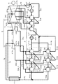
図1に示すように、本実施形態の火力発電プラントでは、蒸気タービン1から排気された蒸気F1(排気蒸気)が、復水器2で冷却されて凝縮する。復水器2において凝縮した水F2(復水)は、給水加熱部3で加熱される。そして、給水加熱部3において加熱された水F3(給水)は、ボイラ4で加熱され、蒸気F4(主蒸気)が生成される。ボイラ4で生成された蒸気F4が蒸気タービン1に作動媒体として供給される。これにより、蒸気タービン1が発電機14を駆動させて、発電が行われる。   As shown in FIG. 1, in the thermal power plant according to the present embodiment, steam F1 (exhausted steam) exhausted from the steam turbine 1 is cooled by the condenser 2 and condensed. The water F2 (condensed water) condensed in the condenser 2 is heated by the feed water heating unit 3. Then, the water F3 (water supply) heated in the water supply heating unit 3 is heated by the boiler 4 to generate steam F4 (main steam). Steam F4 generated by the boiler 4 is supplied to the steam turbine 1 as a working medium. Thereby, the steam turbine 1 drives the generator 14 to generate power.

本実施形態において、火力発電プラントは、再生サイクルおよび再熱サイクルを構成するように、蒸気タービン1と復水器2と給水加熱部3とボイラ4との各部が構成されている。以下より、火力発電プラントを構成する各部の詳細について順次説明する。   In the present embodiment, in the thermal power plant, the steam turbine 1, the condenser 2, the feedwater heating unit 3, and the boiler 4 are configured to constitute a regeneration cycle and a reheating cycle. Hereinafter, the details of each component constituting the thermal power plant will be sequentially described.

本実施形態において、蒸気タービン1は、高圧タービン部11、中圧タービン部12、および、低圧タービン部13によって構成されている。蒸気タービン1は、高圧タービン部11と中圧タービン部12と低圧タービン部13とにおいて、タービンロータ(図示省略)が回転することで、発電機14を駆動させる。発電機14の駆動によって生じた電力は、電力系統(図示省略)に出力される。   In the present embodiment, the steam turbine 1 includes a high-pressure turbine unit 11, an intermediate-pressure turbine unit 12, and a low-pressure turbine unit 13. The steam turbine 1 drives the generator 14 by rotating a turbine rotor (not shown) in the high-pressure turbine section 11, the medium-pressure turbine section 12, and the low-pressure turbine section 13. Power generated by driving the generator 14 is output to a power system (not shown).

具体的には、蒸気タービン1のうち、高圧タービン部11は、単流式であって、ボイラ4から蒸気F4が作動媒体として供給口A11から流入し、排気口A11bから蒸気B1bが流出する。ここでは、ボイラ4で生成された蒸気F4は、蒸気止め弁(図示省略)および蒸気加減弁(図示省略)を経由して、高圧タービン部11に導入される。そして、高圧タービン部11の排気口A11bから流出した蒸気B1bのうち、大部分の蒸気B1b_1は、ボイラ4に流れ、ボイラ4で再び加熱される。これに対して、排気口A11bから流出した蒸気B1bのうち、残りの蒸気B1b_2は、給水加熱部3に流れる。この他に、高圧タービン部11は、抽気口A11aが形成されており、抽気口A11aから蒸気B1aが流出し、その蒸気B1aが給水加熱部3へ流れる。   Specifically, the high-pressure turbine section 11 of the steam turbine 1 is of a single-flow type, in which steam F4 flows in from the boiler 4 as a working medium from a supply port A11, and steam B1b flows out from an exhaust port A11b. Here, the steam F4 generated by the boiler 4 is introduced into the high-pressure turbine unit 11 via a steam stop valve (not shown) and a steam control valve (not shown). Most of the steam B1b_1 out of the steam B1b flowing out of the exhaust port A11b of the high-pressure turbine unit 11 flows to the boiler 4 and is heated again by the boiler 4. On the other hand, of the steam B1b flowing out of the exhaust port A11b, the remaining steam B1b_2 flows to the feedwater heating unit 3. In addition, the high-pressure turbine unit 11 is provided with a bleed port A11a, and steam B1a flows out of the bleed port A11a, and the steam B1a flows to the feedwater heating unit 3.

蒸気タービン1のうち、中圧タービン部12は、ボイラ4において再度加熱された蒸気B4(再熱蒸気)が作動媒体として供給口A12から流入し、排気口A12b,A12cから蒸気B1d,B12が流出する。ここでは、ボイラ4において再度加熱された蒸気B4は、インターセプト弁(図示省略)を経由して、中圧タービン部12に導入される。中圧タービン部12の排気口A12bから流出した蒸気B1dは、給水加熱部3へ流れる。また、中圧タービン部12の排気口A12cから流出した蒸気B12は、低圧タービン部13へ流れる。この他に、中圧タービン部12は、抽気口A12aが形成されており、抽気口A12aから蒸気B1cが流出し、その蒸気B1cが給水加熱部3へ流れる。   In the steam turbine 1, in the medium-pressure turbine section 12, steam B4 (reheated steam) heated again in the boiler 4 flows in from a supply port A12 as a working medium, and steams B1d and B12 flow out from exhaust ports A12b and A12c. I do. Here, the steam B4 reheated in the boiler 4 is introduced into the intermediate pressure turbine section 12 via an intercept valve (not shown). The steam B1d flowing out from the exhaust port A12b of the intermediate pressure turbine section 12 flows to the feedwater heating section 3. Further, the steam B12 flowing out from the exhaust port A12c of the intermediate pressure turbine section 12 flows to the low pressure turbine section 13. In addition, the medium pressure turbine section 12 is provided with a bleed port A12a, and steam B1c flows out of the bleed port A12a, and the steam B1c flows to the feedwater heating section 3.

蒸気タービン1のうち、低圧タービン部13は、複流型であり、供給口A13から作動流体として流入した蒸気B12が低圧タービン部13の内部で分岐して流れ、排気口A13cから蒸気F1が流出する。排気口A13cから流出した蒸気F1は、復水器2へ流れる。この他に、低圧タービン部13は、複数の抽気口A13a,A13bが形成されている。低圧タービン部13においては、抽気口A13aから流出した蒸気B1eと共に、その抽気口A13aよりも下流に位置する抽気口A13bから流出した蒸気B1fが、給水加熱部3へ流れる。   In the steam turbine 1, the low-pressure turbine section 13 is of a double-flow type, and steam B12 flowing as a working fluid from the supply port A13 branches and flows inside the low-pressure turbine section 13, and steam F1 flows out from the exhaust port A13c. . The steam F1 flowing out of the exhaust port A13c flows to the condenser 2. In addition, the low-pressure turbine section 13 has a plurality of bleed ports A13a and A13b. In the low-pressure turbine section 13, together with the steam B1e flowing out of the bleed port A13a, the steam B1f flowing out of the bleed port A13b located downstream of the bleed port A13a flows to the feedwater heating section 3.

復水器2は、低圧タービン部13の排気口A13cから排出された蒸気F1を冷却し凝縮させるために設置されている。復水器2は、たとえば、海水や大気を冷却媒体として用いて、蒸気F1の冷却を行う。復水器2で凝縮した水F2は、復水ポンプP2によって加圧されて、給水加熱部3に移送される。   The condenser 2 is installed to cool and condense the steam F1 discharged from the exhaust port A13c of the low-pressure turbine unit 13. The condenser 2 cools the steam F1 using, for example, seawater or the atmosphere as a cooling medium. The water F2 condensed in the condenser 2 is pressurized by the condensate pump P2 and transferred to the feed water heating unit 3.

給水加熱部3は、蒸気タービン1から抽気された蒸気B1a,B1b_2,B1c,B1d,B1e,B1fを用いて、復水器2で凝縮した水F2を加熱し、その加熱した水F3をボイラ4に供給するように構成されている。つまり、本実施形態の火力発電プラントは、再生サイクルを構成している。   The feed water heating unit 3 heats the water F2 condensed in the condenser 2 using the steam B1a, B1b_2, B1c, B1d, B1e, B1f extracted from the steam turbine 1, and converts the heated water F3 into a boiler 4 It is configured to supply to. That is, the thermal power plant of the present embodiment constitutes a regeneration cycle.

給水加熱部3は、給水加熱器31〜35を複数備えている。   The feed water heating unit 3 includes a plurality of feed water heaters 31 to 35.

本実施形態の給水加熱部3においては、第1高圧給水加熱器31(31a,31b)、第2高圧給水加熱器32(32a,32b)、および、第3高圧給水加熱器33(33a,33b)が、設置されており、高圧給水加熱部(高圧給水加熱器群)を構成している。ここでは、第1高圧給水加熱器31aと第2高圧給水加熱器32aと第3高圧給水加熱器33aとが直列に並んでいる。これと共に、第1高圧給水加熱器31bと第2高圧給水加熱器32bと第3高圧給水加熱器33bとが直列に並んでいる。そして、第1高圧給水加熱器31aと第2高圧給水加熱器32aと第3高圧給水加熱器33aとで構成された一方の組と、第1高圧給水加熱器31bと第2高圧給水加熱器32bと第3高圧給水加熱器33bとで構成された他方の組とが並列に並んでいる。   In the feed water heating section 3 of the present embodiment, the first high pressure feed water heater 31 (31a, 31b), the second high pressure feed water heater 32 (32a, 32b), and the third high pressure feed water heater 33 (33a, 33b). ) Are provided, and constitute a high-pressure feedwater heating unit (high-pressure feedwater heater group). Here, the first high-pressure feedwater heater 31a, the second high-pressure feedwater heater 32a, and the third high-pressure feedwater heater 33a are arranged in series. At the same time, the first high pressure feed water heater 31b, the second high pressure feed water heater 32b, and the third high pressure feed water heater 33b are arranged in series. One set of the first high pressure feed water heater 31a, the second high pressure feed water heater 32a, and the third high pressure feed water heater 33a, the first high pressure feed water heater 31b, and the second high pressure feed water heater 32b And the other set including the third high-pressure feed water heater 33b are arranged in parallel.

また、給水加熱部3においては、第1低圧給水加熱器34および第2低圧給水加熱器35が設置されており、低圧給水加熱部(低圧給水加熱器群)を構成している。   Further, in the feedwater heating section 3, a first low-pressure feedwater heater 34 and a second low-pressure feedwater heater 35 are installed, and constitute a low-pressure feedwater heating section (low-pressure feedwater heater group).

給水加熱器31〜35のそれぞれは、たとえば、シェルの内部にチューブが収容されているシェル&チューブ式の熱交換器である。   Each of the feedwater heaters 31 to 35 is, for example, a shell-and-tube heat exchanger in which a tube is housed inside a shell.

さらに、給水加熱部3においては、脱気器311が設けられている。脱気器311は、たとえば、直接接触式の熱交換器である。   Further, in the feed water heating unit 3, a deaerator 311 is provided. The deaerator 311 is, for example, a direct contact heat exchanger.

給水加熱部3において、複数の給水加熱器31〜35および脱気器311のそれぞれに加熱媒体として供給される蒸気B1a,B1b_2,B1c,B1d,B1e,B1f(抽気蒸気)のそれぞれは、復水器2で凝縮した水F2の流れに沿って、圧力が順次高くなっている。そして、給水加熱部3において、復水器2で凝縮した水F2は、低圧給水加熱器(第2低圧給水加熱器35、第1低圧給水加熱器34)、脱気器311、高圧給水加熱器(第3高圧給水加熱器33、第2高圧給水加熱器32、および、第1高圧給水加熱器31)を順次流れるときに、蒸気B1a,B1b_2,B1c,B1d,B1e,B1fの熱によって加熱されて、温度が上昇する。   In the feedwater heating unit 3, each of the steams B1a, B1b_2, B1c, B1d, B1e, and B1f (extracted steam) supplied as a heating medium to each of the plurality of feedwater heaters 31 to 35 and the deaerator 311 is condensed. The pressure increases sequentially along the flow of the water F2 condensed in the vessel 2. Then, in the feedwater heating unit 3, the water F2 condensed in the condenser 2 is supplied to the low-pressure feedwater heater (the second low-pressure feedwater heater 35, the first low-pressure feedwater heater 34), the deaerator 311 and the high-pressure feedwater heater. When sequentially flowing through the (third high-pressure feedwater heater 33, the second high-pressure feedwater heater 32, and the first high-pressure feedwater heater 31), they are heated by the heat of the steams B1a, B1b_2, B1c, B1d, B1e, B1f. And the temperature rises.

高圧給水加熱器(第3高圧給水加熱器33、第2高圧給水加熱器32、および、第1高圧給水加熱器31)では、脱気器311を流出した水F311が2つに分岐して流れる。ここでは、その分岐された一方の水F311aが、第1高圧給水加熱器31aと第2高圧給水加熱器32aと第3高圧給水加熱器33aとで構成された一方の組を流れることで加熱される。また、その分岐された他方の水F311bが、第1高圧給水加熱器31bと第2高圧給水加熱器32bと第3高圧給水加熱器33bとで構成された一方の組を流れることで加熱される。このように、本実施形態の給水加熱部3は、複数の給水加熱器31〜35が多段階に構成されている。   In the high-pressure feedwater heaters (the third high-pressure feedwater heater 33, the second high-pressure feedwater heater 32, and the first high-pressure feedwater heater 31), the water F311 flowing out of the deaerator 311 branches into two and flows. . Here, one of the branched waters F311a is heated by flowing through one set of a first high-pressure feedwater heater 31a, a second high-pressure feedwater heater 32a, and a third high-pressure feedwater heater 33a. You. In addition, the other water F311b that is branched is heated by flowing through one set of the first high-pressure feedwater heater 31b, the second high-pressure feedwater heater 32b, and the third high-pressure feedwater heater 33b. . As described above, the feed water heating unit 3 of the present embodiment includes a plurality of feed water heaters 31 to 35 in multiple stages.

給水加熱部3を構成する各部について更に詳細に説明する。   Each part constituting the feed water heating unit 3 will be described in more detail.

給水加熱部3のうち、第1高圧給水加熱器31a,31bは、高圧タービン部11の抽気口A11aから供給される蒸気B1aと、第2高圧給水加熱器32a,32bから供給される水F32a,F32bとの間において、熱交換が行われる。この熱交換により、第2高圧給水加熱器32a,32bから流出した水F32a,F32bは、第1高圧給水加熱器31a,31bで加熱される。この一方で、高圧タービン部11の抽気口A11aから流出した蒸気B1aは、第1高圧給水加熱器31a,31bでの熱交換により冷却されて凝縮し、ドレン水B31a,B31bとして第2高圧給水加熱器32a,32bへ流出する。   In the feed water heating unit 3, the first high pressure feed water heaters 31a and 31b are provided with steam B1a supplied from the bleed port A11a of the high pressure turbine unit 11 and water F32a supplied from the second high pressure feed water heaters 32a and 32b. Heat exchange is performed with the F32b. By this heat exchange, the water F32a, F32b flowing out of the second high-pressure feedwater heaters 32a, 32b is heated by the first high-pressure feedwater heaters 31a, 31b. On the other hand, the steam B1a flowing out of the extraction port A11a of the high-pressure turbine unit 11 is cooled and condensed by heat exchange in the first high-pressure feedwater heaters 31a and 31b, and is heated as the second high-pressure feedwater as drain water B31a and B31b. It flows out to vessels 32a and 32b.

給水加熱部3のうち、第2高圧給水加熱器32a,32bは、高圧タービン部11の排気口A11bから供給される蒸気B1b_2と、第3高圧給水加熱器33a,33bから供給される水F33a,F33bとの間において、熱交換が行われる。この熱交換により、第3高圧給水加熱器33a,33bから流出した水F33a,F33bは、第2高圧給水加熱器32a,32bで加熱される。この一方で、高圧タービン部11の排気口A11bから流出した蒸気B1b_2は、第2高圧給水加熱器32a,32bでの熱交換により冷却されて凝縮し、ドレン水B32a,B32bとして第3高圧給水加熱器33a,33bへ流出する。   In the feed water heating unit 3, the second high pressure feed water heaters 32a and 32b include steam B1b_2 supplied from the exhaust port A11b of the high pressure turbine unit 11, and water F33a supplied from the third high pressure feed water heaters 33a and 33b. Heat exchange is performed with F33b. By this heat exchange, the water F33a, F33b flowing out of the third high-pressure feedwater heaters 33a, 33b is heated by the second high-pressure feedwater heaters 32a, 32b. On the other hand, the steam B1b_2 flowing out from the exhaust port A11b of the high-pressure turbine unit 11 is cooled and condensed by heat exchange in the second high-pressure feedwater heaters 32a and 32b, and is heated as the third high-pressure feedwater as drain water B32a and B32b. It flows out to vessels 33a and 33b.

給水加熱部3のうち、第3高圧給水加熱器33a,33bは、中圧タービン部12の抽気口A12aから供給される蒸気B1cと、脱気器311から供給される水F311a,F311bとの間において、熱交換が行われる。この熱交換により、脱気器311から流出した水F311a,F311bは、第3高圧給水加熱器33a,33bで加熱される。この一方で、中圧タービン部12の抽気口A12aから流出した蒸気B1cは、第3高圧給水加熱器33a,33bでの熱交換により冷却されて凝縮し、ドレン水B33a,B33bとして脱気器311へ流出する。   In the feed water heating section 3, the third high pressure feed water heaters 33a and 33b are between the steam B1c supplied from the bleed port A12a of the intermediate pressure turbine section 12 and the water F311a and F311b supplied from the deaerator 311. In, heat exchange is performed. By this heat exchange, the water F311a, F311b flowing out of the deaerator 311 is heated by the third high-pressure feedwater heaters 33a, 33b. On the other hand, the steam B1c flowing out from the bleed port A12a of the intermediate-pressure turbine section 12 is cooled and condensed by heat exchange in the third high-pressure feedwater heaters 33a and 33b, and is deaerated as drain water B33a and B33b. Outflow to

給水加熱部3のうち、脱気器311は、中圧タービン部12の排気口A12bから供給される蒸気B1dが、第1低圧給水加熱器34から供給される水F34に混合されて加熱されることによって、その水F34について脱気を行う。脱気器311は、広義には給水加熱器の一種であって、第1低圧給水加熱器34から供給された水F34に溶解している気体を取り除くと共に、加熱を行う。脱気器311で脱気された水F311は、給水ポンプP311によって加圧された後に分岐し、その分岐した水F311a,F311bが第3高圧給水加熱器33a,33bに移送される。   In the feed water heating unit 3, the deaerator 311 is heated by mixing steam B 1 d supplied from the exhaust port A 12 b of the intermediate pressure turbine unit 12 with water F 34 supplied from the first low pressure feed water heater 34. Thereby, the water F34 is degassed. The deaerator 311 is a kind of feedwater heater in a broad sense, and removes gas dissolved in the water F34 supplied from the first low-pressure feedwater heater 34 and performs heating. The water F311 degassed by the deaerator 311 is branched after being pressurized by the water supply pump P311, and the branched water F311a, F311b is transferred to the third high-pressure water heaters 33a, 33b.

給水加熱部3のうち、第1低圧給水加熱器34は、低圧タービン部13の抽気口A13aから供給される蒸気B1eと、第2低圧給水加熱器35から供給される水F35との間において、熱交換が行われる。この熱交換により、第2低圧給水加熱器35から流出した水F35は、加熱される。この一方で、低圧タービン部13の抽気口A13aから流出した蒸気B1eは、第1低圧給水加熱器34での熱交換により冷却されて凝縮し、ドレン水B34として第2低圧給水加熱器35に流出する。   In the feed water heating unit 3, the first low pressure feed water heater 34 is provided between the steam B1e supplied from the extraction port A13a of the low pressure turbine unit 13 and the water F35 supplied from the second low pressure feed water heater 35. Heat exchange takes place. By this heat exchange, the water F35 flowing out of the second low-pressure feedwater heater 35 is heated. On the other hand, the steam B1e flowing out of the extraction port A13a of the low-pressure turbine section 13 is cooled and condensed by heat exchange in the first low-pressure feedwater heater 34, and flows out to the second low-pressure feedwater heater 35 as drain water B34. I do.

給水加熱部3において、第2低圧給水加熱器35は、低圧タービン部13の抽気口A13bから供給される蒸気B1fと、復水器2から復水ポンプP2を介して供給される水F2との間において、熱交換が行われる。この熱交換により、復水器2を流出した水F2は、第2低圧給水加熱器35で加熱される。この一方で、低圧タービン部13の抽気口A13bから流出した蒸気B1fは、第2低圧給水加熱器35での熱交換により冷却されて凝縮し、ドレン水B35として復水器2に流出する。   In the feed water heating unit 3, the second low pressure feed water heater 35 is configured to supply steam B 1 f supplied from the bleed port A 13 b of the low pressure turbine unit 13 and water F 2 supplied from the condenser 2 via the condensate pump P 2. In between, heat exchange takes place. By this heat exchange, the water F2 flowing out of the condenser 2 is heated by the second low-pressure feedwater heater 35. On the other hand, the steam B1f flowing out of the extraction port A13b of the low-pressure turbine section 13 is cooled and condensed by heat exchange in the second low-pressure feedwater heater 35, and flows out to the condenser 2 as drain water B35.

ボイラ4は、給水加熱部3で加熱された水F3が流入する。ここでは、給水加熱部3において、第1高圧給水加熱器31a,31bで加熱された水F31a,F31bが合流した後に、その合流した水F3が被加熱媒体として供給される。そして、ボイラ4は、たとえば、燃焼により発生する燃焼排ガスを用いて、その給水加熱部3から供給された水F3を加熱することで蒸発させる。ボイラ4で生じた蒸気F4は、高圧タービン部11に作動媒体として供給される。   The water F <b> 3 heated by the feedwater heating unit 3 flows into the boiler 4. Here, in the feedwater heating unit 3, after the waters F31a and F31b heated by the first high-pressure feedwater heaters 31a and 31b join, the combined water F3 is supplied as a medium to be heated. And the boiler 4 evaporates by heating the water F3 supplied from the feed water heating part 3 using the combustion exhaust gas generated by combustion, for example. The steam F4 generated in the boiler 4 is supplied to the high-pressure turbine unit 11 as a working medium.

この他に、ボイラ4は、高圧タービン部11の排気口A11bから流出した蒸気B1bのうち大部分の蒸気B1b_1が流入し、その蒸気B1b_1を再度加熱する。ボイラ4で再度加熱された蒸気B4は、中圧タービン部12に作動媒体として供給される。このように、本実施形態の火力発電プラントは、ボイラ4で蒸気を再熱する再熱サイクルで構成されている。   In addition, in the boiler 4, most of the steam B1b_1 out of the steam B1b flowing out from the exhaust port A11b of the high-pressure turbine section 11 flows in, and heats the steam B1b_1 again. The steam B <b> 4 heated again by the boiler 4 is supplied to the medium pressure turbine unit 12 as a working medium. As described above, the thermal power plant according to the present embodiment is configured by the reheat cycle in which the steam is reheated by the boiler 4.

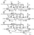
給水加熱部3の詳細構成に関して、図2を用いて説明する。   The detailed configuration of the feed water heating unit 3 will be described with reference to FIG.

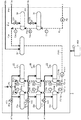
本実施形態の給水加熱部3においては、図2に示すように、複数の抽気絞り弁V31〜V35が設けられている。本実施形態では、複数の抽気絞り弁V31〜V35は、多段階の給水加熱器31〜35の各段に設けられている。   In the feed water heating section 3 of the present embodiment, as shown in FIG. 2, a plurality of bleeding throttle valves V31 to V35 are provided. In the present embodiment, the plurality of bleeding throttle valves V31 to V35 are provided at each stage of the multi-stage feed water heaters 31 to 35.

具体的には、第1の高圧抽気絞り弁V31は、第1高圧給水加熱器31a,31bに加熱媒体として供給する蒸気B1aの流量を調整するために設置されている。第2の高圧抽気絞り弁V32は、第2高圧給水加熱器32a,32bに加熱媒体として供給する蒸気B1b_2の流量を調整するために設置されている。そして、第3の高圧抽気絞り弁V33は、第3高圧給水加熱器33a,33bに加熱媒体として供給する蒸気B1cの流量を調整するために設置されている。   Specifically, the first high-pressure bleeding throttle valve V31 is provided for adjusting the flow rate of steam B1a supplied as a heating medium to the first high-pressure feedwater heaters 31a and 31b. The second high-pressure bleeding throttle valve V32 is provided to adjust the flow rate of steam B1b_2 supplied as a heating medium to the second high-pressure feedwater heaters 32a and 32b. The third high-pressure bleeding throttle valve V33 is provided for adjusting the flow rate of steam B1c supplied as a heating medium to the third high-pressure feedwater heaters 33a and 33b.

これと共に、第1の低圧抽気絞り弁V34は、第1低圧給水加熱器34に加熱媒体として供給する蒸気B1eの流量を調整するために設置されている。そして、第2の低圧抽気絞り弁V35は、第2低圧給水加熱器35に加熱媒体として供給する蒸気B1fの流量を調整するために設置されている。   At the same time, the first low-pressure bleeding throttle valve V34 is provided for adjusting the flow rate of steam B1e supplied as a heating medium to the first low-pressure feedwater heater 34. The second low-pressure bleeding throttle valve V35 is provided to adjust the flow rate of steam B1f supplied as a heating medium to the second low-pressure feedwater heater 35.

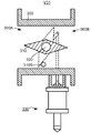
抽気絞り弁の構成について図3を用いて説明する。図3においては、複数の抽気絞り弁V31〜V35のうち、第1の高圧抽気絞り弁V31の断面を模式的に示しているが、他も同様である。   The configuration of the bleed throttle valve will be described with reference to FIG. FIG. 3 schematically shows a cross section of the first high-pressure bleeding throttle valve V31 among the plurality of bleeding throttle valves V31 to V35, but the same applies to other sections.

図3に示すように、第1の高圧抽気絞り弁V31は、バタフライ弁であって、管状の弁ケーシング300の内部においてディスク状の弁体310が弁棒320と共に回転することによって、開閉動作が行われるように構成されている。   As shown in FIG. 3, the first high-pressure bleeding throttle valve V <b> 31 is a butterfly valve, and the opening / closing operation is performed by rotating the disc-shaped valve element 310 together with the valve rod 320 inside the tubular valve casing 300. It is configured to be performed.

ここでは、弁ケーシング300の管軸方向に対して直交する方向に弁棒320が延在するように設置されている。そして、弁棒320は、弁棒320の延在方向を回転軸として、駆動装置330によって回転する。   Here, the valve stem 320 is installed so as to extend in a direction orthogonal to the pipe axis direction of the valve casing 300. Then, the valve stem 320 is rotated by the driving device 330 about the extending direction of the valve stem 320 as a rotation axis.

駆動装置330は、シリンダの内部にピストン(図示省略)が収容されており、シリンダの内部の油圧を制御することによってピストンが移動する油圧駆動装置である。駆動装置330は、ピストンに連結された操作ロッドがリンク部材を介して弁棒320に連結されており、ピストンの移動に応じて弁棒320と共に弁体310を回転させることによって、第1の高圧抽気絞り弁V31の開閉動作を行うように構成されている。つまり、本実施形態において、第1の高圧抽気絞り弁V31は、油圧弁であって、油圧に応じて開度が調整されるように構成されている。   The drive device 330 is a hydraulic drive device in which a piston (not shown) is housed inside a cylinder, and the piston moves by controlling the oil pressure inside the cylinder. The driving device 330 has a first high-pressure valve in which an operation rod connected to a piston is connected to a valve stem 320 via a link member, and the valve 310 is rotated together with the valve stem 320 in accordance with the movement of the piston. The bleeding throttle valve V31 is configured to open and close. That is, in the present embodiment, the first high-pressure bleed throttle valve V31 is a hydraulic valve, and is configured such that the opening degree is adjusted according to the hydraulic pressure.

第1の高圧抽気絞り弁V31を全て開けた全開状態にするには、ディスク状の弁体310が弁ケーシング300の管軸方向に沿うように、弁体310が回転する。これにより、弁体310の外周面と弁ケーシング300の内周面との間が最も離れた状態になる(図中の実線で示す状態)。その結果、弁ケーシング300において蒸気B1aが入口300Aから出口300Bへ流れる。   To bring the first high-pressure bleeding throttle valve V31 into the fully opened state, the valve 310 rotates so that the disc-shaped valve 310 extends along the pipe axis of the valve casing 300. As a result, the outermost surface of the valve 310 and the innermost surface of the valve casing 300 are in the most distant state (the state shown by the solid line in the figure). As a result, in the valve casing 300, the steam B1a flows from the inlet 300A to the outlet 300B.

これに対して、第1の高圧抽気絞り弁V31を全て閉めた全閉状態にするときには、ディスク状の弁体310が弁ケーシング300の管軸方向に対して直交するように弁体310が回転する。これにより、弁体310の外周面と弁ケーシング300の内周面とが接触した状態になる(図中の破線で示す状態)。その結果、弁ケーシング300において入口300Aから出口300Bへ流れる蒸気B1aが遮断される。   On the other hand, when the first high-pressure bleeding throttle valve V <b> 31 is fully closed, the valve 310 is rotated so that the disc-shaped valve 310 is orthogonal to the pipe axis direction of the valve casing 300. I do. As a result, the outer peripheral surface of the valve body 310 and the inner peripheral surface of the valve casing 300 come into contact with each other (the state shown by the broken line in the figure). As a result, the steam B1a flowing from the inlet 300A to the outlet 300B in the valve casing 300 is shut off.

図2に示すように、本実施形態の給水加熱部3においては、複数の給水温度計T31a〜T33a,T31b〜T33b,T34,T35,T311a,T311b,T2が設置されている。   As shown in FIG. 2, in the feed water heating section 3 of the present embodiment, a plurality of feed water thermometers T31a to T33a, T31b to T33b, T34, T35, T311a, T311b, and T2 are installed.

具体的には、給水温度計T31a,T31bは、第1高圧給水加熱器31a,31bから流出した水F31a,F31bの流路に設置されており、その水F31a,F31bの温度を計測する。給水温度計T32a,T32bは、第2高圧給水加熱器32a,32bから流出した水F32a,F32bの流路に設置されており、その水F32a,F32bの温度を計測する。給水温度計T33a,T33bは、第3高圧給水加熱器33a,33bから流出した水F33a,F33bの流路に設置されており、その水F33a,F33bの温度を計測する。   Specifically, the feedwater thermometers T31a and T31b are installed in the flow path of the water F31a and F31b flowing out of the first high-pressure feedwater heaters 31a and 31b, and measure the temperature of the water F31a and F31b. The feedwater thermometers T32a and T32b are installed in the flow path of the water F32a and F32b flowing out of the second high-pressure feedwater heaters 32a and 32b, and measure the temperature of the water F32a and F32b. The feedwater thermometers T33a and T33b are installed in the flow path of the water F33a and F33b flowing out of the third high-pressure feedwater heaters 33a and 33b, and measure the temperature of the water F33a and F33b.

これと共に、脱気器311から流出した後に給水ポンプP311を介して第3高圧給水加熱器33a,33bに流入する水F311の温度を計測するように、給水温度計T311a,T311bが水F311の流路に設置されている。   At the same time, the feed water thermometers T311a and T311b measure the temperature of the water F311 so that the temperature of the water F311 flowing into the third high-pressure feedwater heaters 33a and 33b via the feedwater pump P311 after flowing out of the deaerator 311 is measured. It is installed on the road.

また、第1低圧給水加熱器34から流出した水F34の温度を計測するように、給水温度計T34が水F34の流路に設置されている。第2低圧給水加熱器35から流出した水F35の温度を計測するように、給水温度計T35が水F35の流路に設置されている。さらに、復水器2から流出した後に復水ポンプP2を介して第2低圧給水加熱器35に流入する水F2の温度を計測するように、給水温度計T2が水F2の流路に設置されている。   Further, a feedwater thermometer T34 is provided in the flow path of the water F34 so as to measure the temperature of the water F34 flowing out of the first low-pressure feedwater heater 34. A feedwater thermometer T35 is installed in the flow path of the water F35 so as to measure the temperature of the water F35 flowing out of the second low-pressure feedwater heater 35. Further, a feed water thermometer T2 is installed in the flow path of the water F2 so as to measure the temperature of the water F2 flowing into the second low-pressure feed water heater 35 via the condensate pump P2 after flowing out of the condenser 2. ing.

本実施形態では、複数の給水温度計T31a〜T33a,T31b〜T33b,T34,T35,T311a,T311b,T2のそれぞれは、給水加熱器31a〜33a,31b〜33b,34,35のそれぞれにおいて、流入する水の入口温度と流出する水の出口温度との温度差を算出するために設置されている。   In the present embodiment, each of the plurality of feedwater thermometers T31a to T33a, T31b to T33b, T34, T35, T311a, T311b, and T2 flows into the feedwater heaters 31a to 33a, 31b to 33b, 34, and 35, respectively. It is installed to calculate the temperature difference between the inlet temperature of flowing water and the outlet temperature of flowing water.

具体的には、第1高圧給水加熱器31a,31bにおいて入口に供給される水F32a,F32bの入口温度と出口から排出される水F31a,F31bの出口温度との温度差に関しては、給水温度計T31a,T31bで検出された温度から、給水温度計T32a,T32bで検出された温度を差し引いた差分処理を行うことによって算出される。第2高圧給水加熱器32a,32bにおける入口温度と出口温度との温度差に関しては、給水温度計T32a,T32bで検出された温度から、給水温度計T33a,T33bで検出された温度を差し引いた差分処理を行うことによって算出される。同様に、第3高圧給水加熱器33a,33bにおける入口温度と出口温度との温度差に関しては、給水温度計T33a,T33bで検出された温度から、給水温度計T311a,T311bで検出された温度を差し引いた差分処理を行うことによって算出される。   Specifically, regarding the temperature difference between the inlet temperature of the water F32a and F32b supplied to the inlet and the outlet temperature of the water F31a and F31b discharged from the outlet in the first high-pressure feedwater heaters 31a and 31b, a feedwater thermometer is used. It is calculated by performing a difference process in which the temperatures detected by the feedwater thermometers T32a and T32b are subtracted from the temperatures detected by T31a and T31b. Regarding the temperature difference between the inlet temperature and the outlet temperature in the second high-pressure feed water heaters 32a and 32b, the difference obtained by subtracting the temperature detected by the feed water thermometers T33a and T33b from the temperature detected by the feed water thermometers T32a and T32b. It is calculated by performing the processing. Similarly, regarding the temperature difference between the inlet temperature and the outlet temperature in the third high-pressure feedwater heaters 33a and 33b, the temperature detected by the feedwater thermometers T311a and T311b is calculated from the temperature detected by the feedwater thermometers T33a and T33b. It is calculated by performing the subtraction processing.

これと共に、第1低圧給水加熱器34における入口温度と出口温度との温度差に関しては、給水温度計T34で検出された温度から、給水温度計T35で検出された温度を差し引いた差分処理を行うことによって算出される。第2低圧給水加熱器35における入口温度と出口温度との温度差に関しては、給水温度計T35で検出された温度から、給水温度計T2で検出された温度を差し引いた差分処理を行うことによって算出される。   At the same time, with respect to the temperature difference between the inlet temperature and the outlet temperature in the first low-pressure feed water heater 34, a difference process of subtracting the temperature detected by the feed water thermometer T35 from the temperature detected by the feed water thermometer T34 is performed. It is calculated by: The temperature difference between the inlet temperature and the outlet temperature in the second low-pressure feedwater heater 35 is calculated by performing a difference process of subtracting the temperature detected by the feedwater thermometer T2 from the temperature detected by the feedwater thermometer T35. Is done.

本実施形態の火力発電プラントは、更に、制御装置800を備えている。制御装置800は、演算器(図示省略)とメモリ装置(図示省略)とを含み、メモリ装置が記憶しているプログラムを用いて演算器が演算処理を行うことによって、各部の制御を行うように構成されている。   The thermal power plant according to the present embodiment further includes a control device 800. The control device 800 includes an arithmetic unit (not shown) and a memory device (not shown). The arithmetic unit performs arithmetic processing using a program stored in the memory device to control each unit. It is configured.

ここでは、制御装置800は、操作指令や検出データなどが入力信号として入力される。そして、制御装置800は、その入力された入力信号に基づいて演算処理を行い、制御信号CTLを出力信号として各部に出力することで、各部の動作を制御する。   Here, the control device 800 receives an operation command, detection data, and the like as an input signal. Then, control device 800 performs arithmetic processing based on the input signal that has been input, and outputs the control signal CTL as an output signal to each unit, thereby controlling the operation of each unit.

制御装置800は、通常運転の場合には抽気絞り弁V31〜V35の開度を所定量に調整する。そして、制御装置800は、電力系統において系統周波数が急速に減少したときには、発電機14の出力を「通常運転」の場合よりも急速に増加させる「出力増大運転」を行う。制御装置800は、「出力増大運転」を実行する際には、抽気絞り弁V31〜V35の動作を制御することによって、給水加熱部3に供給する加熱媒体(蒸気B1a,B1b_2,B1c,B1e,B1f)の流量を通常運転の場合よりも低減させる。   Control device 800 adjusts the degree of opening of bleed throttle valves V31 to V35 to a predetermined amount during normal operation. Then, when the system frequency is rapidly reduced in the power system, control device 800 performs “output increasing operation” in which the output of generator 14 is increased more rapidly than in the case of “normal operation”. When executing the “power increase operation”, the control device 800 controls the operation of the bleed throttle valves V31 to V35 to thereby control the heating medium (steam B1a, B1b_2, B1c, B1e, The flow rate of B1f) is reduced as compared with the case of normal operation.

詳細については後述するが、「出力増大運転」の開始を実行した際には、制御装置800は、復水器2から給水加熱部3を介してボイラ4へ供給される水F31a〜F33a,F31b〜F33b,F34,F35の温度に基づいて、抽気絞り弁V31〜V35の動作を制御する。つまり、制御装置800は、給水加熱部3において被加熱媒体として流れる水F31a〜F33a,F31b〜F33b,F34,F35の温度に応じて、抽気絞り弁V31〜V35の開度調整を行う。   Although the details will be described later, when the start of the “power increase operation” is executed, the control device 800 controls the water F31a to F33a, F31b supplied from the condenser 2 to the boiler 4 via the feedwater heating unit 3. Based on the temperatures of F33b, F34, and F35, the operation of the bleed throttle valves V31 to V35 is controlled. That is, the control device 800 adjusts the degree of opening of the bleeding throttle valves V31 to V35 according to the temperatures of the water F31a to F33a, F31b to F33b, F34, and F35 flowing as the medium to be heated in the feedwater heating unit 3.

本実施形態において、制御装置800は、複数の給水温度計T31a〜T33a,T31b〜T33b,T34,T35,T311a,T311b,T2が得た温度データに基づいて、給水加熱器31a〜33a,31b〜33b,34,35において、流入する水の温度と流出する水の温度との温度差を算出する。そして、その温度差の算出値が、温度差について予め設定した上限値を超えるか否かを制御装置800が判断する。   In the present embodiment, the control device 800 controls the feedwater heaters 31a to 33a, 31b to based on the temperature data obtained by the plurality of feedwater thermometers T31a to T33a, T31b to T33b, T34, T35, T311a, T311b, and T2. At 33b, 34 and 35, the temperature difference between the temperature of the inflowing water and the temperature of the outflowing water is calculated. Then, control device 800 determines whether or not the calculated value of the temperature difference exceeds a preset upper limit value for the temperature difference.

そして、その温度差の算出値が上限値を超える場合には、制御装置800は、抽気絞り弁V31〜V35の開度を調整する。これに対して、温度差の算出値が予め設定した上限値以下である場合には、制御装置800は、抽気絞り弁V31〜V35の開度を保持する。   Then, when the calculated value of the temperature difference exceeds the upper limit value, control device 800 adjusts the degree of opening of bleed throttle valves V31 to V35. On the other hand, when the calculated value of the temperature difference is equal to or smaller than the preset upper limit, the control device 800 holds the opening degrees of the bleeding throttle valves V31 to V35.

制御装置800の詳細構成について図4を用いて説明する。図4では、「出力増大運転」を行う際に、制御装置800において、第2高圧給水加熱器32aに供給される蒸気B1b_2の流量を調整するために、第2の高圧抽気絞り弁V32の開度を制御する部分を代表例として示している。   The detailed configuration of the control device 800 will be described with reference to FIG. In FIG. 4, when performing the “power increase operation”, the controller 800 opens the second high-pressure bleed throttle valve V32 in order to adjust the flow rate of the steam B1b_2 supplied to the second high-pressure feedwater heater 32a. The part for controlling the degree is shown as a representative example.

図4に示すように、制御装置800は、周波数急減検出器80と関数発生器81とPID制御器813と高値選択器83とを備える(PID;Proportional−Integral−Differential)。   As shown in FIG. 4, the control device 800 includes a frequency drop detector 80, a function generator 81, a PID controller 813, and a high-value selector 83 (PID; Proportional-Integral-Differential).

周波数急減検出器80は、図4に示すように、外部から系統周波数の検出値Sfが入力信号として入力される。周波数急減検出器80は、予め規定されている系統周波数の設定値から、入力された系統周波数の検出値Sfを差し引いた値を求める。そして、周波数急減検出器80は、その差し引いた値が閾値よりも大きい場合に、その差し引いた値に応じた出力増指令値S0を出力する。   As shown in FIG. 4, the frequency sudden decrease detector 80 receives a detection value Sf of the system frequency from the outside as an input signal. The frequency sudden decrease detector 80 obtains a value obtained by subtracting the input detection value Sf of the system frequency from the preset value of the system frequency. Then, when the subtracted value is larger than the threshold value, the frequency sudden decrease detector 80 outputs the output increase command value S0 according to the subtracted value.

関数発生器81は、図4に示すように、周波数急減検出器80から出力増指令値S0が入力信号として入力される。そして、関数発生器81は、その出力増指令値S0に応じた開度指令値SV32_0を出力信号として出力する。ここでは、関数発生器81は、出力増指令値S0に応じて第2の高圧抽気絞り弁V32の開度を減少させる開度指令値SV32_0を出力する。   As shown in FIG. 4, the function generator 81 receives the output increase command value S0 from the sudden drop detector 80 as an input signal. Then, the function generator 81 outputs an opening command value SV32_0 corresponding to the output increase command value S0 as an output signal. Here, the function generator 81 outputs an opening command value SV32_0 for decreasing the opening of the second high-pressure bleed throttle valve V32 according to the output increasing command value S0.

PID制御器813は、図4に示すように、給水温度計T31aで検出された温度ST31aと、給水温度計T32aで検出された温度ST32aとを用いて算出された算出値ΔST31a_2が、入力信号として入力される。具体的には、給水温度計T31aで検出された温度ST31aから、給水温度計T32aで検出された温度ST32aを減算することによって、温度差ΔST31aが求められる。この温度差ΔST31aは、第1高圧給水加熱器31a,31bにおいて入口に供給される水F32a,F32bの温度と出口から排出される水F31a,F31bの温度との温度差である。そして、その温度差について予め設定した温度差上限値ΔST_U1から、上記のように算出した温度差ΔST31aを減算することによって、差分値ΔST31a_1が求められる。その後、その差分値ΔST31a_1に「−1」を積算して正負を反転させることで、算出値ΔST31a_2が求められる。そして、その求めた算出値ΔST31a_2が、PID制御器813に入力される。PID制御器813は、その算出値ΔST31a_2に応じた開度指令値SV32_3を出力信号として出力する。   As shown in FIG. 4, the PID controller 813 outputs, as an input signal, a calculated value ΔST31a_2 calculated using the temperature ST31a detected by the feedwater thermometer T31a and the temperature ST32a detected by the feedwater thermometer T32a. Will be entered. Specifically, the temperature difference ΔST31a is obtained by subtracting the temperature ST32a detected by the feedwater thermometer T32a from the temperature ST31a detected by the feedwater thermometer T31a. The temperature difference ΔST31a is a temperature difference between the temperatures of the water F32a, F32b supplied to the inlet and the temperatures of the water F31a, F31b discharged from the outlet in the first high-pressure feedwater heaters 31a, 31b. Then, the difference value ΔST31a_1 is obtained by subtracting the temperature difference ΔST31a calculated as described above from the temperature difference upper limit value ΔST_U1 set in advance for the temperature difference. Thereafter, the difference value ΔST31a_1 is multiplied by “−1” and the sign is inverted to obtain a calculated value ΔST31a_2. Then, the calculated value ΔST31a_2 is input to the PID controller 813. The PID controller 813 outputs an opening command value SV32_3 corresponding to the calculated value ΔST31a_2 as an output signal.

たとえば、温度差上限値ΔST_U1が20℃であって、温度差ΔST31aが22℃である場合には、PID制御器813に入力される算出値ΔST31a_2は、「+2℃」となる。PID制御器813は、この算出値ΔST31a_2に応じて第2の高圧抽気絞り弁V32の開度を増加させる開度指令値SV32_3を出力する。   For example, when temperature difference upper limit ΔST_U1 is 20 ° C. and temperature difference ΔST31a is 22 ° C., calculated value ΔST31a_2 input to PID controller 813 is “+ 2 ° C.”. The PID controller 813 outputs an opening command value SV32_3 for increasing the opening of the second high-pressure bleeding throttle valve V32 according to the calculated value ΔST31a_2.

高値選択器83は、図4に示すように、関数発生器81が出力した開度指令値SV32_0と、PID制御器813が出力した開度指令値SV32_3とが入力信号として入力される。高値選択器83は、関数発生器81が出力した開度指令値SV32_0と、PID制御器813が出力した開度指令値SV32_3とのうち最も高い値を選択する。そして、高値選択器83は、その選択した開度指令値SV32を第2の高圧抽気絞り弁V32に出力信号として出力する。   4, the opening command value SV32_0 output from the function generator 81 and the opening command value SV32_3 output from the PID controller 813 are input to the high value selector 83 as input signals. The high value selector 83 selects the highest value among the opening command value SV32_0 output by the function generator 81 and the opening command value SV32_3 output by the PID controller 813. Then, the high value selector 83 outputs the selected opening command value SV32 to the second high-pressure bleeding throttle valve V32 as an output signal.

なお、図示を省略しているが、制御装置800は、第2高圧給水加熱器32bに供給される蒸気B1b_2の流量を調整するために、上記のPID制御器813と同様なPID制御器を更に備えている。また、制御装置800において、第2の高圧抽気絞り弁V32以外の抽気絞り弁の動作を制御する部分についても、上記と同様に構成されている。   Although not shown, the control device 800 further includes a PID controller similar to the above PID controller 813 in order to adjust the flow rate of the steam B1b_2 supplied to the second high-pressure feedwater heater 32b. Have. Also, in the control device 800, a portion that controls the operation of the bleed throttle valve other than the second high-pressure bleed throttle valve V32 is configured in the same manner as described above.

以下より、本実施形態の火力発電プラントの動作に関して、「通常運転」を行う場合と、「出力増大運転」を行う場合とに分けて説明を行う。   Hereinafter, the operation of the thermal power plant according to the present embodiment will be described separately for a case where “normal operation” is performed and a case where “output increase operation” is performed.

本実施形態の火力発電プラントにおいて「通常運転」を行うときの動作の一例に関して説明する。   An example of the operation when performing “normal operation” in the thermal power plant of the present embodiment will be described.

上記の火力発電プラントにおいて「通常運転」が行われる場合には、ボイラ4から蒸気F4が蒸気タービン1に供給され、蒸気タービン1で仕事を行う。蒸気タービン1においては、蒸気F4が高圧タービン部11に作動媒体として供給されて仕事を行う。そして、高圧タービン部11から排気された蒸気B1bのうち、大部分の蒸気B1b_1がボイラ4で再度加熱された後に、そのボイラ4で再度加熱された蒸気B4が中圧タービン部12に作動媒体として供給されて仕事を行う。その後、中圧タービン部12から排出された蒸気B12が低圧タービン部13に作動媒体として供給されて仕事を行う。低圧タービン部13から排出された蒸気F1は、復水器2において凝縮され、その復水器2で凝縮された水F2が給水加熱部3で加熱される。給水加熱部3において、復水器2で凝縮された水F2は、蒸気タービン1から抽気された蒸気B1a,B1b_2,B1c,B1d,B1e,B1fの熱によって加熱される。そして、給水加熱部3において加熱された水F3がボイラ4で加熱されることによって、ボイラ4で蒸気F4が生成される。その後、ボイラ4で生成された蒸気F4は、上述したように、蒸気タービン1に作動媒体として供給される。   When “normal operation” is performed in the above-described thermal power plant, steam F4 is supplied from the boiler 4 to the steam turbine 1, and the steam turbine 1 performs work. In the steam turbine 1, the steam F4 is supplied to the high-pressure turbine unit 11 as a working medium to perform work. Then, after most of the steam B1b_1 among the steam B1b exhausted from the high-pressure turbine unit 11 is heated again by the boiler 4, the steam B4 reheated by the boiler 4 is supplied to the intermediate-pressure turbine unit 12 as a working medium. Supplied to do work. Thereafter, the steam B12 discharged from the intermediate pressure turbine section 12 is supplied to the low pressure turbine section 13 as a working medium to perform work. The steam F1 discharged from the low-pressure turbine unit 13 is condensed in the condenser 2, and the water F2 condensed in the condenser 2 is heated in the feedwater heating unit 3. In the feed water heating unit 3, the water F2 condensed in the condenser 2 is heated by the heat of the steams B1a, B1b_2, B1c, B1d, B1e, and B1f extracted from the steam turbine 1. Then, the water F3 heated in the feed water heating unit 3 is heated in the boiler 4, so that the steam F4 is generated in the boiler 4. Thereafter, the steam F4 generated by the boiler 4 is supplied to the steam turbine 1 as a working medium, as described above.

給水加熱部3では、蒸気タービン1から抽気された蒸気B1a,B1b_2,B1c,B1e,B1fが、抽気絞り弁V31〜V35を介して、加熱媒体として供給される。「通常運転」を行う場合において、火力発電プラントが一定の発電出力(定格出力)で安定的に稼働している状態では、発電効率を最大に保持するために、制御装置800は、抽気絞り弁V31〜V35を、たとえば、全開状態にしている。   In the feedwater heating unit 3, the steam B1a, B1b_2, B1c, B1e, B1f extracted from the steam turbine 1 is supplied as a heating medium via the extraction throttle valves V31 to V35. When performing “normal operation”, in a state where the thermal power plant is stably operating at a constant power generation output (rated output), in order to maintain the power generation efficiency to the maximum, the control device 800 uses the bleed throttle valve. V31 to V35 are, for example, fully opened.

本実施形態の火力発電プラントにおいて「出力増大運転」を行う場合の動作の一例について説明する。「出力増大運転」は、発電機14の出力を急速に増大させるために行われる。   An example of the operation when the “power increase operation” is performed in the thermal power plant according to the present embodiment will be described. The “power increase operation” is performed to rapidly increase the output of the generator 14.

「出力増大運転」を実行するときの流れの一例について、図5および図6を用いて説明する。   An example of the flow when executing the “power increase operation” will be described with reference to FIGS. 5 and 6.

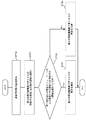
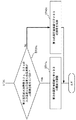
まず、図5に示すように、系統周波数の急減検出が行われる(ST10)。   First, as shown in FIG. 5, a sudden decrease in the system frequency is detected (ST10).

具体的には、系統周波数の検出値から設定値を差し引いた値が所定の閾値よりも大きくなったときには、出力増大要求の操作指令として、出力増指令値S0(図4参照)が出力される。   Specifically, when a value obtained by subtracting the set value from the detected value of the system frequency becomes larger than a predetermined threshold, an output increase command value S0 (see FIG. 4) is output as an operation command for an output increase request. .

つぎに、図5に示すように、「出力増大運転」を開始する(ST20)。   Next, as shown in FIG. 5, "power increase operation" is started (ST20).

ここでは、出力増指令値S0に応じて制御装置800が各部の動作を制御することによって、「出力増大運転」が開始される。「出力増大運転」は、給水加熱部3に供給する加熱媒体(蒸気B1a,B1b_2,B1c,B1e,B1f)の流量を通常運転の場合よりも低減するように、抽気絞り弁V31〜V35の動作を制御することで開始される。   Here, the “power increase operation” is started by the control device 800 controlling the operation of each unit according to the output increase command value S0. The “power increase operation” is an operation of the bleeding throttle valves V31 to V35 such that the flow rate of the heating medium (steam B1a, B1b_2, B1c, B1e, B1f) supplied to the feedwater heating unit 3 is reduced as compared with the normal operation. It is started by controlling.

「出力増大運転」を開始する際には、複数の抽気絞り弁V31〜V35のうち少なくとも一つについて、開度を小さくする。本実施形態では、第2の高圧抽気絞り弁V32について全開状態よりも開度を小さい状態に変える。これにより、第2高圧給水加熱器32a,32bに加熱媒体として供給する蒸気B1b_2の流量が絞られる。その結果、蒸気タービン1を構成する中圧タービン部12において膨張仕事を行う蒸気の量が増加するため、発電機14の出力を「通常運転」の場合よりも急速に増加させることができる。   When starting the "power increase operation", the opening degree of at least one of the plurality of bleeding throttle valves V31 to V35 is reduced. In the present embodiment, the opening degree of the second high-pressure bleeding throttle valve V32 is changed to a state smaller than the fully opened state. Thereby, the flow rate of the steam B1b_2 supplied as the heating medium to the second high-pressure feedwater heaters 32a and 32b is reduced. As a result, the amount of steam that performs expansion work in the intermediate-pressure turbine unit 12 that configures the steam turbine 1 increases, so that the output of the generator 14 can be increased more rapidly than in the case of “normal operation”.

つぎに、図5に示すように、第1高圧給水加熱器31a,31bの入口温度と出口温度との温度差ΔST31a,ΔST31bが温度差上限値ΔST_U1を超えているか否かを判断する(ST30)。   Next, as shown in FIG. 5, it is determined whether or not the temperature differences ΔST31a, ΔST31b between the inlet temperature and the outlet temperature of the first high-pressure feed water heaters 31a, 31b exceed the temperature difference upper limit value ΔST_U1 (ST30). .

「出力増大運転」の実行のために上述したように第2高圧給水加熱器32a,32bに加熱媒体として供給する蒸気B1b_2の流量を絞った場合には、復水器2で凝縮した水F2の流れ方向において、その第2高圧給水加熱器32a,32bよりも下流側に位置する第1高圧給水加熱器31a,31bでは、熱交換量が大きくなる。その結果、第1高圧給水加熱器31a,31bにおいて入口に供給される水F32a,F32bの温度ST32a,ST32bと出口から排出される水F31a,F31bの温度ST31a,ST31bとの温度差ΔST31a,ΔST31bが大きくなって、その温度差ΔST31a,ΔST31bが、予め設定した温度差上限値ΔST_U1を超える可能性が高まる(図6参照)。また、第1高圧給水加熱器31a,31bにおいて熱交換量を大きくするために、加熱媒体(抽気蒸気)の流速が配管の制限流速を超過する可能性が高まる。   When the flow rate of the steam B1b_2 supplied as the heating medium to the second high-pressure feedwater heaters 32a and 32b is reduced as described above to execute the “power increase operation”, the water F2 condensed in the condenser 2 is reduced. In the flow direction, the first high-pressure feed water heaters 31a and 31b located downstream of the second high-pressure feed water heaters 32a and 32b have a large heat exchange amount. As a result, the temperature differences ΔST31a, ΔST31b between the temperatures ST32a, ST32b of the water F32a, F32b supplied to the inlet and the temperatures ST31a, ST31b of the water F31a, F31b discharged from the outlet in the first high-pressure feedwater heaters 31a, 31b. The temperature difference ΔST31a, ΔST31b becomes more likely to exceed a preset temperature difference upper limit value ΔST_U1 (see FIG. 6). Further, in order to increase the amount of heat exchange in the first high-pressure feed water heaters 31a and 31b, there is a high possibility that the flow rate of the heating medium (extracted steam) exceeds the flow rate limit of the pipe.

このため、本実施形態では、上述したように、給水温度計T31a,T31bで検出された温度ST31a,ST31bから給水温度計T32a,T32bで検出された温度ST32a,ST32bを差し引いた差分処理を制御装置800が行うことによって、第1高圧給水加熱器31a,31bにおける温度差ΔST31a,ΔST31bを算出する。そして、その第1高圧給水加熱器31a,31bにおける温度差ΔST31a,ΔST31bと、予め設定した温度差上限値ΔST_U1との間について、制御装置800が比較処理を行う。これにより、第1高圧給水加熱器31a,31bにおける温度差ΔST31a,ΔST31bが、温度差上限値ΔST_U1を超えているか否かを制御装置800が判断する。   For this reason, in the present embodiment, as described above, the control device performs a difference process in which the temperatures ST32a and ST32b detected by the feedwater thermometers T32a and T32b are subtracted from the temperatures ST31a and ST31b detected by the feedwater thermometers T31a and T31b. By performing 800, the temperature differences ΔST31a and ΔST31b in the first high-pressure feedwater heaters 31a and 31b are calculated. Then, control device 800 performs a comparison process between temperature differences ΔST31a and ΔST31b in first high-pressure feedwater heaters 31a and 31b and a preset temperature difference upper limit value ΔST_U1. Thereby, control device 800 determines whether or not temperature differences ΔST31a and ΔST31b in first high-pressure feedwater heaters 31a and 31b exceed temperature difference upper limit ΔST_U1.

図5に示すように、第1高圧給水加熱器31a,31bにおける温度差ΔST31a,ΔST31bが温度差上限値ΔST_U1を超えている場合(Yes)には、第2の高圧抽気絞り弁V32の開度について調整する(ST41)。   As shown in FIG. 5, when the temperature differences ΔST31a and ΔST31b in the first high-pressure feed water heaters 31a and 31b exceed the temperature difference upper limit ΔST_U1 (Yes), the opening degree of the second high-pressure bleed throttle valve V32 is set. Is adjusted (ST41).

ここでは、「出力増大運転」の開始によって全開状態よりも開度が小さい状態になっている上限値を超えた給水加熱器31a、31bの上流に位置する給水加熱器32a、32bへの加熱媒体を調整する第2の高圧抽気絞り弁V32を制御装置800が開ける。つまり、第2高圧給水加熱器32a,32bに加熱媒体として供給する蒸気B1b_2の流量を増加させる(図6参照)。   Here, the heating medium is supplied to the feed water heaters 32a and 32b located upstream of the feed water heaters 31a and 31b, which have exceeded the upper limit in which the opening degree is smaller than the fully opened state due to the start of the "power increase operation". The control device 800 opens the second high-pressure bleeding throttle valve V32 for adjusting the pressure. That is, the flow rate of the steam B1b_2 supplied as the heating medium to the second high-pressure feedwater heaters 32a and 32b is increased (see FIG. 6).

たとえば、温度差ΔST31a,ΔST31bから温度差上限値ΔST_U1を差し引いた差分処理を行い、その差分処理で算出した差分値に応じて、第2の高圧抽気絞り弁V32の開度が大きくなるように制御を行う。   For example, a difference process is performed by subtracting the temperature difference upper limit value ΔST_U1 from the temperature differences ΔST31a and ΔST31b, and control is performed such that the opening degree of the second high-pressure bleed throttle valve V32 increases according to the difference value calculated by the difference process. I do.

その結果、第1高圧給水加熱器31a,31bにおける温度差ΔST31a,ΔST31bは、予め設定した温度差上限値ΔST_U1以下になる。   As a result, the temperature differences ΔST31a and ΔST31b in the first high-pressure feedwater heaters 31a and 31b are equal to or less than a preset temperature difference upper limit value ΔST_U1.

これに対して、図5に示すように、第1高圧給水加熱器31a,31bにおける温度差ΔST31が温度差上限値ΔST_U1以下である場合(No)には、第2の高圧抽気絞り弁V32の開度を保持する(ST42)。   On the other hand, as shown in FIG. 5, when the temperature difference ΔST31 between the first high-pressure feed water heaters 31a and 31b is equal to or smaller than the temperature difference upper limit value ΔST_U1 (No), the second high-pressure bleed throttle valve V32 is turned off. The opening is held (ST42).

ここでは、「出力増大運転」の開始によって第2の高圧抽気絞り弁V32が全開状態よりも開度が小さい状態になっているので、制御装置800は、その状態を保持させる。つまり、第2高圧給水加熱器32a,32bに加熱媒体として供給する蒸気B1b_2の流量を保持させる。   Here, since the second high-pressure bleeding throttle valve V32 is in a state in which the opening degree is smaller than the fully opened state by the start of the “power increase operation”, the control device 800 keeps the state. That is, the flow rate of the steam B1b_2 supplied as the heating medium to the second high-pressure feedwater heaters 32a and 32b is maintained.

なお、上記においては、説明を簡略化するために、2つの第1高圧給水加熱器31a,31bのそれぞれにおける温度差ΔST31a,ΔST31bが同じである場合を例示している。2つの第1高圧給水加熱器31a,31bのそれぞれにおける温度差ΔST31a,ΔST31bが異なる場合には、2つの温度差ΔST31a,ΔST31bのうち大きい値と、温度差上限値ΔST_U1との間を比較する。そして、その比較結果に基づいて、上記と同様に、第2の高圧抽気絞り弁V32の動作を制御する。   In the above, for simplification of the description, the case where the temperature differences ΔST31a and ΔST31b in the two first high-pressure feedwater heaters 31a and 31b are the same is illustrated. When the temperature differences ΔST31a and ΔST31b in the two first high-pressure feedwater heaters 31a and 31b are different, a comparison is made between the larger value of the two temperature differences ΔST31a and ΔST31b and the temperature difference upper limit ΔST_U1. Then, based on the result of the comparison, the operation of the second high-pressure bleed throttle valve V32 is controlled in the same manner as described above.

以上のように、本実施形態では、出力増大運転を実行しているときには、復水器2から給水加熱部3を介してボイラ4へ流れる水F31a〜F33a,F31b〜F33b,F34,F35の温度に基づいて、抽気絞り弁V31〜V35の動作を制御する。ここでは、給水加熱部3を構成する複数の給水加熱器31a〜33a,31b〜33b,34,35のそれぞれにおいて流入する水の入口温度と流出する水の出口温度との温度差を算出し、当該算出した温度差の算出値が、予め設定した上限値を超えるか否かを判断する。そして、その算出値が上限値を超える場合には、複数の抽気絞り弁V31〜V35において出力増大運転を開始するときに閉じた抽気絞り弁(本実施形態では、第2の高圧抽気絞り弁V32)を開ける。その結果、上限値を超えた給水加熱器(本実施形態では、第1高圧給水加熱器31a,31b)の温度差が上限値以下になる。また、その給水加熱器(本実施形態では、第1高圧給水加熱器31a,31b)に供給される加熱媒体の流速を配管の制限流速以下に保持することができる。   As described above, in the present embodiment, when the output increase operation is performed, the temperatures of the water F31a to F33a, F31b to F33b, F34, and F35 flowing from the condenser 2 to the boiler 4 via the feedwater heating unit 3 are set. , The operation of the bleed throttle valves V31 to V35 is controlled. Here, the temperature difference between the inlet temperature of the inflowing water and the outlet temperature of the outflowing water in each of the plurality of feedwater heaters 31a to 33a, 31b to 33b, 34, and 35 constituting the feedwater heating unit 3 is calculated, It is determined whether or not the calculated value of the calculated temperature difference exceeds a preset upper limit value. If the calculated value exceeds the upper limit value, the bleeding throttle valve closed when the output increase operation is started in the plurality of bleeding throttle valves V31 to V35 (in the present embodiment, the second high-pressure bleeding throttle valve V32 ) Open. As a result, the temperature difference between the feedwater heaters (in the present embodiment, the first high-pressure feedwater heaters 31a and 31b) exceeding the upper limit value is equal to or less than the upper limit value. Further, the flow rate of the heating medium supplied to the feed water heater (in the present embodiment, the first high-pressure feed water heaters 31a and 31b) can be maintained at or below the flow rate limit of the pipe.

なお、給水加熱器の入口温度と出口温度との温度差の上限値は、給水加熱器の保護のために設定されている。このため、本実施形態では、上記したように、「出力増大運転」を実行する場合においても、給水加熱器の入口温度と出口温度との温度差を上限値以下にすることができるため、給水加熱器の破損防止の効果を得ることができる。   In addition, the upper limit of the temperature difference between the inlet temperature and the outlet temperature of the feedwater heater is set to protect the feedwater heater. For this reason, in the present embodiment, as described above, even when the “power increase operation” is performed, the temperature difference between the inlet temperature and the outlet temperature of the feedwater heater can be made equal to or less than the upper limit value. The effect of preventing breakage of the heater can be obtained.

上記の実施形態では、「出力増大運転」を実行するために、複数の抽気絞り弁V31〜V35のうち、第2の高圧抽気絞り弁V32について開度を全開状態から小さくする場合について例示したが、これに限らない。以下より、具体的な変形例について説明する。   In the above embodiment, the case where the opening degree of the second high-pressure bleeding throttle valve V32 among the plurality of bleeding throttle valves V31 to V35 is reduced from the fully open state in order to execute the “power increase operation” has been described. However, it is not limited to this. Hereinafter, specific modifications will be described.

(変形例1−1)
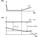
変形例1−1に関して、図7A、図7B、図7C、図8を用いて説明する。図7Aから図7Cのそれぞれは、「出力増大運転」を実行するときの流れを示すフロー図である。図8は、「出力増大運転」を実行するときに、高圧給水加熱器の温度と、高圧抽気絞り弁の開度との関係を示す図である。
(Modification 1-1)
Modification 1-1 will be described with reference to FIGS. 7A, 7B, 7C, and 8. FIG. Each of FIGS. 7A to 7C is a flowchart showing a flow when executing the “power increase operation”. FIG. 8 is a diagram illustrating a relationship between the temperature of the high-pressure feedwater heater and the opening of the high-pressure bleeding throttle valve when performing the “power increase operation”.

図7Aに示すように、系統周波数の急減検出が行われたとき(ST10)には、「出力増大運転」を開始する(ST20)。   As shown in FIG. 7A, when the sudden decrease of the system frequency is detected (ST10), the “power increase operation” is started (ST20).

本変形例において「出力増大運転」を開始する際には、第1の高圧抽気絞り弁V31の開度、第2の高圧抽気絞り弁V32の開度、および、第3の高圧抽気絞り弁V33の開度について、全開状態よりも小さい状態に変える。   When the “power increase operation” is started in this modification, the opening degree of the first high-pressure bleeding throttle valve V31, the opening degree of the second high-pressure bleeding throttle valve V32, and the third high-pressure bleeding throttle valve V33 Is changed to a state smaller than the fully opened state.

「出力増大運転」を開始後、本変形例では、図7Aに示すように、第1高圧給水加熱器31a,31bの出口温度が、温度下限値未満か否かを判断する(ST30a)。ここでは、図8に示すように、給水温度計T31a,T31bが検出した温度に基づいて、制御装置800が上記の判断を行う(図2参照)。   After the “power increase operation” is started, in the present modification, as shown in FIG. 7A, it is determined whether or not the outlet temperatures of the first high-pressure feed water heaters 31a and 31b are lower than the lower temperature limit (ST30a). Here, as shown in FIG. 8, the control device 800 makes the above determination based on the temperatures detected by the feedwater thermometers T31a and T31b (see FIG. 2).

そして、図7Aに示すように、第1高圧給水加熱器31a,31bの出口温度(給水温度計T31a,T31bが検出した温度)が温度下限値未満である場合(Yes)には、第1の高圧抽気絞り弁V31の開度を大きくするように調整を行う(ST41a)。これにより、図8に示すように、第1高圧給水加熱器31a,31bの出口温度が温度下限値未満の状態から温度下限値以上の状態になる。   Then, as shown in FIG. 7A, when the outlet temperatures of the first high-pressure feedwater heaters 31a and 31b (the temperatures detected by the feedwater thermometers T31a and T31b) are lower than the lower temperature limit (Yes), the first high-pressure feedwater heaters 31a and 31b are turned off. Adjustment is performed to increase the opening of the high-pressure bleeding throttle valve V31 (ST41a). Thereby, as shown in FIG. 8, the outlet temperature of the first high-pressure feedwater heaters 31a and 31b is changed from a state where the outlet temperature is lower than the lower temperature limit to a state where the outlet temperature is higher than the lower temperature limit.

これに対して、図7Aに示すように、第1高圧給水加熱器31a,31bの出口温度(給水温度計T31a,T31bが検出した温度)が温度下限値未満でない場合(No)には、第1の高圧抽気絞り弁V31の開度について全開状態よりも小さい状態に保持する(ST42a)。   On the other hand, as shown in FIG. 7A, when the outlet temperatures of the first high-pressure feed water heaters 31a and 31b (the temperatures detected by the feed water thermometers T31a and T31b) are not less than the lower temperature limit (No), The degree of opening of the first high-pressure bleeding throttle valve V31 is kept smaller than the fully opened state (ST42a).

また、本変形例では、図7Bに示すように、第1高圧給水加熱器31a,31bにおいて入口に供給される水F32a,F32bの入口温度と出口から排出される水F31a,F31bの出口温度との温度差ΔST31a,ΔST31bが、予め設定した温度差上限値ΔST_U1を超えるか否かを判断する(ST30b)。ここでは、図8に示すように、給水温度計T31a,T31bが検出した温度と、給水温度計T32a,T32bが検出した温度との温度差ΔST31a,ΔST31bに基づいて、制御装置800が上記の判断を行う(図2参照)。   In this modification, as shown in FIG. 7B, the inlet temperatures of the water F32a, F32b supplied to the inlet and the outlet temperatures of the water F31a, F31b discharged from the outlet in the first high-pressure feedwater heaters 31a, 31b. It is determined whether or not the temperature differences ΔST31a and ΔST31b exceed a preset temperature difference upper limit value ΔST_U1 (ST30b). Here, as shown in FIG. 8, the control device 800 makes the above determination based on the temperature differences ΔST31a and ΔST31b between the temperatures detected by the feedwater thermometers T31a and T31b and the temperatures detected by the feedwater thermometers T32a and T32b. (See FIG. 2).

そして、図7Bに示すように、第1高圧給水加熱器31a,31bにおける温度差ΔST31a,ΔST31bが温度差上限値ΔST_U1を超えた場合(Yes)には、第2の高圧抽気絞り弁V32の開度が大きくなるように調整する(ST41b)。たとえば、図8に示すように、第1の高圧抽気絞り弁V31の開度を大きくした後に、第1高圧給水加熱器31a,31bにおける温度差ΔST31a,ΔST31bが温度差上限値ΔST_U1を超えたときに、第2の高圧抽気絞り弁V32の開度を大きくする。これにより、第1高圧給水加熱器31a,31bにおける温度差ΔST31a,ΔST31bが温度差上限値ΔST_U1を超えた状態から温度差上限値ΔST_U1以下になる。   Then, as shown in FIG. 7B, when the temperature differences ΔST31a and ΔST31b in the first high-pressure feedwater heaters 31a and 31b exceed the temperature difference upper limit ΔST_U1 (Yes), the second high-pressure bleed throttle valve V32 is opened. Adjustment is made to increase the degree (ST41b). For example, as shown in FIG. 8, when the temperature difference ΔST31a, ΔST31b in the first high-pressure feed water heaters 31a, 31b exceeds the temperature difference upper limit value ΔST_U1, after the opening degree of the first high-pressure bleeding throttle valve V31 is increased. Next, the opening degree of the second high-pressure bleeding throttle valve V32 is increased. As a result, the temperature differences ΔST31a, ΔST31b in the first high-pressure feedwater heaters 31a, 31b are reduced from the temperature difference upper limit value ΔST_U1 to the temperature difference upper limit value ΔST_U1 or less.

これに対して、図7Bに示すように、第1高圧給水加熱器31a,31bにおける温度差ΔST31a,ΔST31bが温度差上限値ΔST_U1以下である場合には、第2の高圧抽気絞り弁V32の開度について全開状態よりも小さい状態に保持する(ST42b)。   On the other hand, as shown in FIG. 7B, when the temperature differences ΔST31a and ΔST31b in the first high-pressure feedwater heaters 31a and 31b are equal to or smaller than the temperature difference upper limit ΔST_U1, the opening of the second high-pressure bleeding throttle valve V32 is performed. The degree is kept smaller than the fully open state (ST42b).

更に、本変形例では、図7Cに示すように、第2高圧給水加熱器32a,32bにおいて入口に供給される水F33a,F33bの入口温度と出口から排出される水F32a,F32bの出口温度との温度差ΔST32a,ΔST32bが、予め設定した温度差上限値ΔST_U2を超えるか否かを制御装置800が判断する(ST30c)。ここでは、図8に示すように、給水温度計T32a,T32bが検出した温度と、給水温度計T33a,T33bが検出した温度との温度差ΔST32a,ΔST32bに基づいて、制御装置800が上記の判断を行う(図2参照)。   Furthermore, in this modification, as shown in FIG. 7C, the inlet temperature of the water F33a, F33b supplied to the inlet and the outlet temperature of the water F32a, F32b discharged from the outlet in the second high-pressure feedwater heaters 32a, 32b. The control device 800 determines whether or not the temperature differences ΔST32a and ΔST32b exceed a preset temperature difference upper limit ΔST_U2 (ST30c). Here, as shown in FIG. 8, control device 800 makes the above determination based on temperature differences ΔST32a and ΔST32b between the temperatures detected by feedwater thermometers T32a and T32b and the temperatures detected by feedwater thermometers T33a and T33b. (See FIG. 2).

そして、図7Cに示すように、第2高圧給水加熱器32a,32bにおける温度差ΔST32a,ΔST32bが温度差上限値ΔST_U2を超えた場合(Yes)には、第3の高圧抽気絞り弁V33の開度が大きくなるように調整する(ST41c)。たとえば、図8に示すように、第2の高圧抽気絞り弁V32の開度を大きくした後に、第2高圧給水加熱器32a,32bにおける温度差ΔST32a,ΔST32bが温度差上限値ΔST_U2を超えたときに、第3の高圧抽気絞り弁V33の開度を大きくする。これにより、第2高圧給水加熱器32a,32bにおける温度差ΔST32a,ΔST32bが温度差上限値ΔST_U2を超えた状態から温度差上限値ΔST_U2以下になる。   Then, as shown in FIG. 7C, when the temperature differences ΔST32a and ΔST32b in the second high-pressure feed water heaters 32a and 32b exceed the temperature difference upper limit ΔST_U2 (Yes), the third high-pressure bleed throttle valve V33 is opened. Adjustment is made to increase the degree (ST41c). For example, as shown in FIG. 8, when the temperature difference ΔST32a, ΔST32b in the second high-pressure feed water heaters 32a, 32b exceeds the temperature difference upper limit value ΔST_U2 after the opening degree of the second high-pressure bleeding throttle valve V32 is increased. Next, the opening degree of the third high-pressure bleeding throttle valve V33 is increased. As a result, the temperature difference ΔST32a, ΔST32b in the second high-pressure feedwater heaters 32a, 32b becomes lower than the temperature difference upper limit ΔST_U2 from the state exceeding the temperature difference upper limit ΔST_U2.

これに対して、図7Cに示すように、第2高圧給水加熱器32a,32bにおける温度差ΔST32a,ΔST32bが温度差上限値ΔST_U2以下である場合には、第3の高圧抽気絞り弁V33の開度について全開状態よりも小さい状態に保持する(ST42c)。   On the other hand, as shown in FIG. 7C, when the temperature differences ΔST32a and ΔST32b in the second high-pressure feedwater heaters 32a and 32b are equal to or smaller than the temperature difference upper limit ΔST_U2, the opening of the third high-pressure bleed throttle valve V33 is performed. The degree is kept smaller than the fully open state (ST42c).

(変形例1−2)
変形例1−2において、「出力増大運転」を実行する際には、たとえば、第2の低圧抽気絞り弁V35の開度を全開状態よりも小さい状態に変える。この場合には、第2低圧給水加熱器35よりも下流側に位置する第1低圧給水加熱器34において熱交換量が大きくなる可能性が高まる。このため、第1低圧給水加熱器34において入口に供給される水F35の入口温度と出口から排出される水F34の出口温度との温度差が、予め設定した温度差上限値を超えるか否かを制御装置800が判断する。
(Modification 1-2)
In the modified example 1-2, when performing the “power increase operation”, for example, the opening degree of the second low-pressure bleeding throttle valve V35 is changed to a state smaller than the fully opened state. In this case, the possibility that the amount of heat exchange becomes large in the first low-pressure feedwater heater 34 located downstream of the second low-pressure feedwater heater 35 increases. For this reason, whether the temperature difference between the inlet temperature of the water F35 supplied to the inlet and the outlet temperature of the water F34 discharged from the outlet in the first low-pressure feedwater heater 34 exceeds a preset temperature difference upper limit value or not. Is determined by the control device 800.

第1低圧給水加熱器34における温度差が温度差上限値以下である場合には、第2の低圧抽気絞り弁V35の開度を全開状態よりも小さい状態に保持する。   When the temperature difference in the first low-pressure feed water heater 34 is equal to or less than the temperature difference upper limit value, the opening degree of the second low-pressure bleeding throttle valve V35 is kept smaller than the fully opened state.

これに対して、第1低圧給水加熱器34における温度差が温度差上限値を超えている場合には、第2の低圧抽気絞り弁V35を開ける。その結果、第1低圧給水加熱器34において入口に供給される水F35の入口温度と出口から排出される水F34の出口温度との温度差は、予め設定した温度差上限値以下になる。   On the other hand, when the temperature difference in the first low-pressure feedwater heater 34 exceeds the upper limit of the temperature difference, the second low-pressure bleeding throttle valve V35 is opened. As a result, the temperature difference between the inlet temperature of the water F35 supplied to the inlet and the outlet temperature of the water F34 discharged from the outlet in the first low-pressure feedwater heater 34 is equal to or less than a preset temperature difference upper limit value.

なお、本変形例において、「出力増大運転」を実行する際には、脱気器311よりも上流側に位置する第2低圧給水加熱器35に供給される加熱媒体の流量を「通常運転」の場合よりも低減している。このため、脱気器311に流入する水F34の温度(給水温度)が低下して、脱気器311においてフラッディングが生ずることを、本実施形態では、効果的に防止可能である。   In this modification, when performing the “power increase operation”, the flow rate of the heating medium supplied to the second low-pressure feedwater heater 35 located upstream of the deaerator 311 is set to the “normal operation”. It is lower than the case. Therefore, in the present embodiment, it is possible to effectively prevent the temperature (water supply temperature) of the water F34 flowing into the deaerator 311 from decreasing and causing flooding in the deaerator 311.

(変形例1−3)
変形例1−3に係る給水加熱部3の詳細構成に関して、図9を用いて説明する。
(Modification 1-3)
The detailed configuration of the feed water heating unit 3 according to the modified example 1-3 will be described with reference to FIG.

本変形例の給水加熱部3においては、上記実施形態の場合と異なり、図9に示すように、第1の高圧抽気絞り弁V31、第2の高圧抽気絞り弁V32、および、第3の高圧抽気絞り弁V33のそれぞれが、2つである。   In the feed water heating section 3 of the present modification, unlike the above embodiment, as shown in FIG. 9, a first high-pressure bleed throttle valve V31, a second high-pressure bleed throttle valve V32, and a third high-pressure bleed throttle valve V32 Each of the bleeding throttle valves V33 is two.

具体的には、一方の第1の高圧抽気絞り弁V31aは、一方の第1高圧給水加熱器31aに加熱媒体として供給する蒸気B1aの流量を調整するために設置されている。そして、他方の第1の高圧抽気絞り弁V31bは、他方の第1高圧給水加熱器31bに加熱媒体として供給する蒸気B1aの流量を調整するために設置されている。一方の第2の高圧抽気絞り弁V32aは、一方の第2高圧給水加熱器32aに加熱媒体として供給する蒸気B1b_2の流量を調整するために設置されている。そして、他方の第2の高圧抽気絞り弁V32bは、他方の第2高圧給水加熱器32bに加熱媒体として供給する蒸気B1b_2の流量を調整するために設置されている。一方の第3の高圧抽気絞り弁V33aは、一方の第3高圧給水加熱器33aに加熱媒体として供給する蒸気B1cの流量を調整するために設置されている。そして、他方の第3の高圧抽気絞り弁V33bは、他方の第3高圧給水加熱器33bに加熱媒体として供給する蒸気B1cの流量を調整するために設置されている。   Specifically, one first high-pressure bleeding throttle valve V31a is provided to adjust the flow rate of steam B1a supplied as a heating medium to one first high-pressure feedwater heater 31a. And the other 1st high pressure bleeding throttle valve V31b is installed in order to adjust the flow rate of steam B1a supplied as a heating medium to the other 1st high pressure feed water heater 31b. The one second high-pressure bleeding throttle valve V32a is provided for adjusting the flow rate of steam B1b_2 supplied as a heating medium to the one second high-pressure feedwater heater 32a. And the other 2nd high pressure bleeding throttle valve V32b is installed in order to adjust the flow rate of steam B1b_2 supplied as a heating medium to the other 2nd high pressure feed water heater 32b. One third high-pressure bleeding throttle valve V33a is provided to adjust the flow rate of steam B1c supplied as a heating medium to one third high-pressure feedwater heater 33a. The other third high-pressure bleeding throttle valve V33b is provided for adjusting the flow rate of steam B1c supplied as a heating medium to the other third high-pressure feedwater heater 33b.

本変形例において、「出力増大運転」を実行する際には、たとえば、第2の高圧抽気絞り弁V32bの開度を全開状態よりも小さい状態に変える。   In the present modified example, when performing the “power increase operation”, for example, the opening degree of the second high-pressure bleeding throttle valve V32b is changed to a state smaller than the fully opened state.

この場合には、第2高圧給水加熱器32bよりも下流側に位置する第1高圧給水加熱器31bにおいて熱交換量が大きくなる可能性が高まる。このため、第1高圧給水加熱器31bにおいて入口に供給される水F32bの入口温度と出口から排出される水F31bの出口温度との温度差が、予め設定した温度差上限値を超えるか否かを制御装置800が判断する。   In this case, the possibility that the heat exchange amount becomes large in the first high-pressure feedwater heater 31b located downstream of the second high-pressure feedwater heater 32b increases. Therefore, whether the temperature difference between the inlet temperature of the water F32b supplied to the inlet and the outlet temperature of the water F31b discharged from the outlet in the first high-pressure feed water heater 31b exceeds a preset temperature difference upper limit value or not. Is determined by the control device 800.

第1高圧給水加熱器31bにおける温度差が温度差上限値以下である場合には、第2の高圧抽気絞り弁V32bの開度について全開状態よりも小さい状態に保持する。   When the temperature difference in the first high-pressure feed water heater 31b is equal to or less than the temperature difference upper limit value, the opening degree of the second high-pressure bleeding throttle valve V32b is kept smaller than the fully opened state.

これに対して、第1高圧給水加熱器31bにおける温度差が温度差上限値を超えている場合には、第2の高圧抽気絞り弁V32bの開度を大きくする。その結果、第1高圧給水加熱器31bにおける温度差は、予め設定した温度差上限値以下になる。   On the other hand, when the temperature difference in the first high pressure feed water heater 31b exceeds the upper limit of the temperature difference, the opening degree of the second high pressure bleeding throttle valve V32b is increased. As a result, the temperature difference in the first high-pressure feedwater heater 31b becomes equal to or less than the preset temperature difference upper limit value.

(その他)
上記においては、第1高圧給水加熱器31(31a,31b)、第2高圧給水加熱器32(32a,32b)、第3高圧給水加熱器33(33a,33b)、第1低圧給水加熱器34、および、第2低圧給水加熱器35を、給水加熱部3が給水加熱器として備える場合について説明したが、これに限らない。給水加熱器は、上記した台数以外の台数に、適宜、変更してもよい。
(Other)
In the above, the first high-pressure feedwater heater 31 (31a, 31b), the second high-pressure feedwater heater 32 (32a, 32b), the third high-pressure feedwater heater 33 (33a, 33b), and the first low-pressure feedwater heater 34. And the case where the feed water heating unit 3 includes the second low-pressure feed water heater 35 as the feed water heater has been described, but the present invention is not limited to this. The number of the feed water heaters may be appropriately changed to a number other than the above number.

<第2実施形態>
第2実施形態に係る火力発電プラントの要部について、図10を用いて説明する。図10に示すように、本実施形態は、一部の構成を除き、上記した第1実施形態と同様であるので、重複部分に関しては適宜説明を省略する。
<Second embodiment>
The main part of the thermal power plant according to the second embodiment will be described with reference to FIG. As shown in FIG. 10, the present embodiment is the same as the above-described first embodiment except for a part of the configuration, and therefore, the description of the overlapping portions will be appropriately omitted.

本実施形態の給水加熱部3においては、図10に示すように、第1実施形態の場合と同様に、複数の抽気絞り弁V31〜V35が設けられている。   As shown in FIG. 10, in the feed water heating section 3 of the present embodiment, a plurality of bleeding throttle valves V31 to V35 are provided as in the case of the first embodiment.

給水加熱器31a〜33a,31b〜33b,34,35は、たとえば、シェル&チューブ式の熱交換器である。給水加熱器31a〜33a,31b〜33b,34,35においては、蒸気タービン1から抽気された蒸気B1a,B1b_2,B1c,B1e,B1fが加熱媒体としてシェルに供給され、復水器2で凝縮した水F2が被加熱媒体としてチューブに供給され、加熱媒体と被加熱媒体との間で熱交換が行われる。水F2は、給水加熱部3で行われた熱交換によって、加熱される。そして、蒸気タービン1から抽気された蒸気B1a,B1b_2,B1c,B1e,B1fは、給水加熱部3で行われた熱交換によって冷却されて凝縮し、ドレン水に変わる。   The feed water heaters 31a to 33a, 31b to 33b, 34, and 35 are, for example, shell-and-tube heat exchangers. In the feed water heaters 31a to 33a, 31b to 33b, 34, and 35, steam B1a, B1b_2, B1c, B1e, and B1f extracted from the steam turbine 1 are supplied to the shell as a heating medium and condensed in the condenser 2. Water F2 is supplied to the tube as a medium to be heated, and heat exchange is performed between the heating medium and the medium to be heated. The water F2 is heated by the heat exchange performed in the feedwater heating unit 3. Then, the steams B1a, B1b_2, B1c, B1e, and B1f extracted from the steam turbine 1 are cooled and condensed by heat exchange performed in the feedwater heating unit 3, and are changed into drain water.

そして、本実施形態の給水加熱部3には、図10に示すように、複数のドレン水温度計X31a〜X33a,X31b〜X33b,X34,X35(器内温度計)が設置されている。これと共に、給水加熱部3には、複数の圧力計P31a〜P33a,P31b〜P33b,P34,P35(器内圧力計)が設置されている。   As shown in FIG. 10, a plurality of drain water thermometers X31a to X33a, X31b to X33b, X34, and X35 (in-chamber thermometers) are installed in the feed water heating unit 3 of the present embodiment. At the same time, a plurality of pressure gauges P31a to P33a, P31b to P33b, P34, and P35 (internal pressure gauges) are installed in the feedwater heating unit 3.

具体的には、第1高圧給水加熱器31a,31bにおいて蒸気B1aが加熱媒体として供給されるシェルの内部に存在するドレン水の温度を計測するように、ドレン水温度計X31a,X31bが設置されていると共に、第1高圧給水加熱器31a,31bのシェルの内部の圧力を計測するように圧力計P31a,P31bが設置されている。第2高圧給水加熱器32a,32bにおいて蒸気B1b_2が加熱媒体として供給されるシェルの内部に存在するドレン水の温度を計測するように、ドレン水温度計X32a,X32bが設置されていると共に、第2高圧給水加熱器32a,32bのシェルの内部の圧力を計測するように、圧力計P32a,P32bが設置されている。第3高圧給水加熱器33a,33bにおいて蒸気B1cが加熱媒体として供給されるシェルの内部に存在するドレン水の温度を計測するように、ドレン水温度計X33a,X33bが設置されていると共に、第3高圧給水加熱器33a,33bのシェルの内部の圧力を計測するように、圧力計P33a,P33bが設置されている。   Specifically, drain water thermometers X31a and X31b are installed so as to measure the temperature of the drain water existing inside the shell to which the steam B1a is supplied as a heating medium in the first high-pressure feed water heaters 31a and 31b. In addition, pressure gauges P31a and P31b are installed to measure the pressure inside the shells of the first high-pressure feedwater heaters 31a and 31b. Drain water thermometers X32a and X32b are installed so as to measure the temperature of the drain water existing inside the shell to which the steam B1b_2 is supplied as the heating medium in the second high-pressure feed water heaters 32a and 32b. Pressure gauges P32a and P32b are installed to measure the pressure inside the shells of the two high-pressure feed water heaters 32a and 32b. Drain water thermometers X33a and X33b are installed so as to measure the temperature of the drain water existing inside the shell to which the steam B1c is supplied as the heating medium in the third high pressure feed water heaters 33a and 33b. Pressure gauges P33a and P33b are installed to measure the pressure inside the shells of the three high-pressure feedwater heaters 33a and 33b.

これと共に、第1低圧給水加熱器34において蒸気B1eが加熱媒体として供給されるシェルの内部に存在するドレン水の温度を計測するように、ドレン水温度計X34が設置されていると共に、第1低圧給水加熱器34のシェルの内部の圧力を計測するように、圧力計P34が設置されている。第2低圧給水加熱器35において蒸気B1fが加熱媒体として供給されるシェルの内部に存在するドレン水の温度を計測するように、ドレン水温度計X35が設置されていると共に、第2低圧給水加熱器35のシェルの内部の圧力を計測するように、圧力計P35が設置されている。   At the same time, a drain water thermometer X34 is installed so as to measure the temperature of the drain water existing inside the shell to which the steam B1e is supplied as the heating medium in the first low-pressure feed water heater 34, A pressure gauge P34 is provided to measure the pressure inside the shell of the low-pressure feedwater heater 34. A drain water thermometer X35 is installed so as to measure the temperature of the drain water existing inside the shell to which the steam B1f is supplied as a heating medium in the second low-pressure feed water heater 35, and the second low-pressure feed water heating is performed. A pressure gauge P35 is provided to measure the pressure inside the shell of the vessel 35.

本実施形態において、ドレン水温度計X31a〜X33a,X31b〜X33b,X34,X35および圧力計P31a〜P33a,P31b〜P33b,P34,P35は、給水加熱器31a〜33a,31b〜33b,34,35の内部で生じたドレン水が蒸気になるドレンフラッシュの発生を監視するために設置されている。   In the present embodiment, the drain water thermometers X31a to X33a, X31b to X33b, X34, X35 and the pressure gauges P31a to P33a, P31b to P33b, P34, P35 are feed water heaters 31a to 33a, 31b to 33b, 34, 35. It is installed to monitor the occurrence of drain flash which turns the drain water generated inside into steam.

制御装置800は、第1実施形態の場合と同様に、「出力増大運転」を実行する際には、抽気絞り弁V31〜V35の動作を制御することによって、給水加熱部3に供給される加熱媒体の流量を通常運転の場合よりも低減させる。加熱媒体の流量を低減させるにあたっては、給水加熱部3において加熱媒体が供給される内部のドレン水温度が加熱媒体の飽和温度より低い状態となる範囲で抽気絞り弁V31〜V35を調整すべく、出力増大運転が開始されてから抽気絞り弁V31〜V35をどの順序でどの程度開けるかを過去の知見をもとに予め作成した手順を記憶させておき、この予め定められた手順で、抽気絞り弁V31〜V35の開度を調整していく。   The control device 800 controls the operation of the bleed throttle valves V31 to V35 to execute the heating to be supplied to the feedwater heating unit 3 when performing the “output increasing operation”, as in the first embodiment. The flow rate of the medium is reduced as compared with the normal operation. In reducing the flow rate of the heating medium, in order to adjust the bleeding throttle valves V31 to V35 in a range in which the temperature of the drain water inside the heating medium supplied to the heating medium in the feedwater heating unit 3 is lower than the saturation temperature of the heating medium, The procedure in which the order and how much the bleeding throttle valves V31 to V35 are opened after the output increasing operation is started is stored based on past knowledge, and the bleeding throttle is performed in accordance with the predetermined procedure. The openings of the valves V31 to V35 are adjusted.

詳細については後述するが、「出力増大運転」を実行しているときには、制御装置800は、給水加熱部3において加熱媒体が供給される内部のドレン水の温度、および、その内部の圧力に基づいて、抽気絞り弁V31〜V35の動作を制御する。つまり、制御装置800は、ドレン水温度計X31a〜X33a,X31b〜X33b,X34,X35が得た温度データ、および、圧力計P31a〜P33a,P31b〜P33b,P34,P35が得た圧力データに基づいて、抽気絞り弁V31〜V35の開度調整を行う。   Although the details will be described later, when the “power increase operation” is being executed, the control device 800 determines the temperature of the drain water inside the heating water supply unit 3 to which the heating medium is supplied, and the pressure inside the drain water. Thus, the operation of the bleeding throttle valves V31 to V35 is controlled. That is, the control device 800 is based on the temperature data obtained by the drain water thermometers X31a to X33a, X31b to X33b, X34, and X35 and the pressure data obtained by the pressure gauges P31a to P33a, P31b to P33b, P34, and P35. Then, the opening degree of the bleeding throttle valves V31 to V35 is adjusted.

制御装置800の詳細構成について図11を用いて説明する。図11では、「出力増大運転」を行う際に、制御装置800において、第2高圧給水加熱器32aに供給される蒸気B1b_2の流量を調整するために、第2の高圧抽気絞り弁V32の開度を制御する部分を代表例として示している。   The detailed configuration of the control device 800 will be described with reference to FIG. In FIG. 11, when performing the “power increase operation”, the control device 800 opens the second high-pressure bleed throttle valve V32 in order to adjust the flow rate of the steam B1b_2 supplied to the second high-pressure feedwater heater 32a. The part for controlling the degree is shown as a representative example.

図11に示すように、制御装置800は、周波数急減検出器80と蒸気表T80と関数発生器81とPID制御器815と高値選択器83とを備える。   As shown in FIG. 11, the control device 800 includes a frequency sudden decrease detector 80, a steam table T80, a function generator 81, a PID controller 815, and a high value selector 83.

周波数急減検出器80は、図11に示すように、外部から系統周波数の検出値Sfが入力信号として入力される。周波数急減検出器80は、予め規定されている系統周波数の設定値から、入力された系統周波数の検出値Sfを差し引いた値を求める。そして、周波数急減検出器80は、その差し引いた値が閾値よりも大きい場合に、その差し引いた値に応じた出力増指令値S0を出力する。   As shown in FIG. 11, the frequency sudden decrease detector 80 receives the detection value Sf of the system frequency from the outside as an input signal. The frequency sudden decrease detector 80 obtains a value obtained by subtracting the input detection value Sf of the system frequency from the preset value of the system frequency. Then, when the subtracted value is larger than the threshold value, the frequency sudden decrease detector 80 outputs the output increase command value S0 according to the subtracted value.

関数発生器81は、図11に示すように、周波数急減検出器80から出力増指令値S0が入力信号として入力される。そして、関数発生器81は、その出力増指令値S0に応じた開度指令値SV32_0を出力信号として出力する。ここでは、関数発生器81は、出力増指令値S0に応じて第2の高圧抽気絞り弁V32の開度を減少させる開度指令値SV32_0を出力する。   As shown in FIG. 11, the function generator 81 receives the output increase command value S0 from the sudden drop detector 80 as an input signal. Then, the function generator 81 outputs an opening command value SV32_0 corresponding to the output increase command value S0 as an output signal. Here, the function generator 81 outputs an opening command value SV32_0 for decreasing the opening of the second high-pressure bleed throttle valve V32 according to the output increasing command value S0.

PID制御器815は、図11に示すように、ドレン水温度計X32aで検出された温度SX32aと、圧力計P32aで検出された圧力SP32aとを用いて算出された算出値ΔSC32aが入力信号として入力される。具体的には、ルックアップテーブル等で構成された蒸気表T80を用いて、圧力計P32aで検出された圧力SP32aに対応する飽和蒸気温度SS32aが求められる。そして、その求めた飽和蒸気温度SS32aから、ドレン水温度計X32aで検出された温度SX32aを減算することによって、温度差ΔSX32aが求められる。そして、その温度差について予め設定した温度差下限値ΔSC_L2(サブクール温度下限値)から、上記のように算出した温度差ΔSX32aを減算することによって、算出値ΔSC32aが求められる。そして、その求めた算出値ΔSC32aが、PID制御器815に入力される。PID制御器815は、その算出値ΔSC32aに応じた開度指令値SV32_5を出力信号として出力する。   As shown in FIG. 11, the PID controller 815 receives, as an input signal, a calculation value ΔSC32a calculated using the temperature SX32a detected by the drain water thermometer X32a and the pressure SP32a detected by the pressure gauge P32a. Is done. Specifically, the saturated steam temperature SS32a corresponding to the pressure SP32a detected by the pressure gauge P32a is obtained using a steam table T80 configured by a look-up table or the like. Then, the temperature difference ΔSX32a is obtained by subtracting the temperature SX32a detected by the drain water thermometer X32a from the obtained saturated steam temperature SS32a. Then, the calculated value ΔSC32a is obtained by subtracting the temperature difference ΔSX32a calculated as described above from the temperature difference lower limit value ΔSC_L2 (subcool temperature lower limit value) preset for the temperature difference. Then, the calculated value ΔSC32a is input to the PID controller 815. The PID controller 815 outputs an opening command value SV32_5 corresponding to the calculated value ΔSC32a as an output signal.

たとえば、温度差下限値SC_L2(サブクール温度下限値)が5℃であって、温度差ΔSX32aが3℃である場合には、PID制御器815に入力される算出値ΔSC32aは、「+2℃」となる。PID制御器815は、この算出値ΔSC32aに応じて第2の高圧抽気絞り弁V32の開度を増加させる開度指令値SV32_5を出力する。   For example, when the temperature difference lower limit SC_L2 (subcool temperature lower limit) is 5 ° C. and the temperature difference ΔSX32a is 3 ° C., the calculated value ΔSC32a input to the PID controller 815 is “+ 2 ° C.” Become. The PID controller 815 outputs an opening command value SV32_5 for increasing the opening of the second high-pressure bleed throttle valve V32 according to the calculated value ΔSC32a.

高値選択器83は、図11に示すように、関数発生器81が出力した開度指令値SV32_0と、PID制御器815が出力した開度指令値SV32_5とが入力信号として入力される。高値選択器83は、関数発生器81が出力した開度指令値SV32_0と、PID制御器815が出力した開度指令値SV32_5とのうち最も高い値を選択する。そして、高値選択器83は、その選択した開度指令値SV32を第2の高圧抽気絞り弁V32に出力信号として出力する。   As shown in FIG. 11, the opening command value SV32_0 output from the function generator 81 and the opening command value SV32_5 output from the PID controller 815 are input to the high value selector 83 as input signals. The high value selector 83 selects the highest value among the opening command value SV32_0 output from the function generator 81 and the opening command value SV32_5 output from the PID controller 815. Then, the high value selector 83 outputs the selected opening command value SV32 to the second high-pressure bleeding throttle valve V32 as an output signal.

なお、図示を省略しているが、制御装置800は、第2高圧給水加熱器32bに供給される蒸気B1b_2の流量を調整するために、上記のPID制御器815と同様なPID制御器を更に備えている。また、制御装置800において、第2の高圧抽気絞り弁V32以外の抽気絞り弁の動作を制御する部分についても、上記と同様に構成されている。   Although not shown, the control device 800 further includes a PID controller similar to the above PID controller 815 in order to adjust the flow rate of the steam B1b_2 supplied to the second high-pressure feedwater heater 32b. Have. Also, in the control device 800, a portion that controls the operation of the bleed throttle valve other than the second high-pressure bleed throttle valve V32 is configured in the same manner as described above.

本実施形態において、上記の「出力増大運転」を実行するときの動作の一例に関して説明する。   In the present embodiment, an example of the operation when executing the above-described “power increase operation” will be described.

本実施形態において系統周波数の急減を検出した時には、制御装置800は、たとえば、第1の高圧抽気絞り弁V31と第2の高圧抽気絞り弁V32と第3の高圧抽気絞り弁V33とのそれぞれについて、開度を小さくする。ここでは、第1の高圧抽気絞り弁V31と第2の高圧抽気絞り弁V32と第3の高圧抽気絞り弁V33との全ての開度に関して、全開状態(K=Kmax=100%)から、全閉状態よりも大きい所定の開度(K=Kx(たとえば、Kx=10%))に変える。たとえば、系統周波数の急減を検出した時から0.5秒以内に、所定の開度に変わる。これにより、第1高圧給水加熱器31a,31bと第2高圧給水加熱器32a,32bと第3高圧給水加熱器33a,33bとのそれぞれに供給される加熱媒体の流量が、「出力増大運転」の実行前の状態よりも絞られる。   When a sudden decrease in the system frequency is detected in the present embodiment, the control device 800 determines, for example, each of the first high-pressure bleed throttle valve V31, the second high-pressure bleed throttle valve V32, and the third high-pressure bleed throttle valve V33. , Reduce the opening. Here, with respect to all the opening degrees of the first high-pressure bleeding throttle valve V31, the second high-pressure bleeding throttle valve V32, and the third high-pressure bleeding throttle valve V33, from the fully open state (K = Kmax = 100%), The opening degree is changed to a predetermined opening degree (K = Kx (for example, Kx = 10%)) larger than that in the closed state. For example, the opening degree is changed to a predetermined degree within 0.5 seconds after the detection of the sudden decrease of the system frequency. As a result, the flow rate of the heating medium supplied to each of the first high-pressure feedwater heaters 31a and 31b, the second high-pressure feedwater heaters 32a and 32b, and the third high-pressure feedwater heaters 33a and 33b increases the "output increase operation". Is narrowed down from the state before execution.

上記のように、「出力増大運転」を実行しているときには、蒸気タービン1において膨張仕事を行う蒸気の量が増加するため、発電機14の出力を「通常運転」の場合よりも急速に増加させることができる。   As described above, when the “power increase operation” is being performed, the amount of steam that performs expansion work in the steam turbine 1 increases, so that the output of the generator 14 increases more rapidly than in the “normal operation”. Can be done.

「出力増大運転」を実行しているとき、第1高圧給水加熱器31a,31bにおいて加熱媒体が供給される内部の圧力は、第1の高圧抽気絞り弁V31の開度が小さくなるに伴って低下する。その後、第1の高圧抽気絞り弁V31の開度が大きくなるに伴い、第1高圧給水加熱器31a,31bにおいて加熱媒体が供給される内部の圧力は、上昇する。このように、「出力増大運転」を実行しているとき、第1高圧給水加熱器31a,31bにおいて加熱媒体が供給される内部の圧力は、変動する。第1高圧給水加熱器31a,31bの内部では、圧力の変動に伴って、加熱媒体の飽和温度も変動する。第1高圧給水加熱器31a,31bにおいて加熱媒体が供給される内部の温度は、加熱媒体の飽和温度よりも低い状態になるように変動する。このため、第1高圧給水加熱器31a,31bにおいてドレンフラッシュが生じない。   When the “power increase operation” is being performed, the internal pressure of the first high-pressure feedwater heaters 31a and 31b to which the heating medium is supplied increases as the opening degree of the first high-pressure bleed throttle valve V31 decreases. descend. Thereafter, as the opening of the first high-pressure bleeding throttle valve V31 increases, the internal pressure of the first high-pressure feed water heaters 31a and 31b to which the heating medium is supplied increases. As described above, when the “power increase operation” is being performed, the internal pressure of the first high-pressure feedwater heaters 31a and 31b to which the heating medium is supplied fluctuates. Inside the first high-pressure feedwater heaters 31a and 31b, the saturation temperature of the heating medium also changes with a change in pressure. The temperature inside the first high pressure feed water heaters 31a and 31b to which the heating medium is supplied fluctuates so as to be lower than the saturation temperature of the heating medium. Therefore, drain flush does not occur in the first high pressure feed water heaters 31a and 31b.

第2高圧給水加熱器32a,32bと第3高圧給水加熱器33a,33bとのそれぞれにおいても同様に、加熱媒体が供給される内部の圧力が変動する。これに伴い、加熱媒体の飽和温度も変動するが、加熱媒体が供給される内部の温度は、加熱媒体の飽和温度よりも低い状態になるように変動する。このため、第2高圧給水加熱器32a,32bおよび第3高圧給水加熱器33a,33bにおいてもドレンフラッシュが生じない。   Similarly, in each of the second high-pressure feedwater heaters 32a and 32b and the third high-pressure feedwater heaters 33a and 33b, the internal pressure at which the heating medium is supplied fluctuates. Accordingly, the saturation temperature of the heating medium also varies, but the temperature inside the supply of the heating medium varies so as to be lower than the saturation temperature of the heating medium. Therefore, no drain flush occurs in the second high-pressure feedwater heaters 32a, 32b and the third high-pressure feedwater heaters 33a, 33b.

更に、本実施形態では、「出力増大運転」を実行しているときには、第1高圧給水加熱器31a,31bと第2高圧給水加熱器32a,32bと第3高圧給水加熱器33a,33bとにおいて計測したドレン水の温度および内部の圧力に基づいて、制御装置800が抽気絞り弁V31〜V33の動作を制御する。ここでは、第1高圧給水加熱器31a,31bと第2高圧給水加熱器32a,32bと第3高圧給水加熱器33a,33bとにおいてドレン水の温度が、飽和温度よりも低い状態を保持するように、制御装置800が抽気絞り弁V31〜V33の動作を制御する。   Furthermore, in the present embodiment, when the “power increase operation” is being performed, the first high-pressure feedwater heaters 31a and 31b, the second high-pressure feedwater heaters 32a and 32b, and the third high-pressure feedwater heaters 33a and 33b are used. The control device 800 controls the operation of the bleed throttle valves V31 to V33 based on the measured drain water temperature and the internal pressure. Here, the first high-pressure feed water heaters 31a and 31b, the second high-pressure feed water heaters 32a and 32b, and the third high-pressure feed water heaters 33a and 33b keep the temperature of the drain water lower than the saturation temperature. Next, the control device 800 controls the operation of the bleed throttle valves V31 to V33.

具体的には、第1高圧給水加熱器31a,31bと第2高圧給水加熱器32a,32bと第3高圧給水加熱器33a,33bとにおいて加熱媒体が供給される内部の圧力について計測した圧力計測値から加熱媒体の飽和温度を算出する。そして、第1高圧給水加熱器31a,31bと第2高圧給水加熱器32a,32bと第3高圧給水加熱器33a,33bとの内部に存在するドレン水の温度を、上記のように算出した飽和温度から減算することによって、温度差を算出する。そして、その温度差について予め設定した温度差下限値ΔSC_L1〜ΔSC_L3(サブクール温度下限値)から、上記のように算出した温度差を減算した算出値に応じて、各高圧抽気絞り弁V31,V32,V33の開度を制御する。   Specifically, pressure measurement is performed on the internal pressure of the heating medium supplied to the first high-pressure feedwater heaters 31a and 31b, the second high-pressure feedwater heaters 32a and 32b, and the third high-pressure feedwater heaters 33a and 33b. The saturation temperature of the heating medium is calculated from the value. Then, the temperature of the drain water existing inside the first high-pressure feed water heaters 31a and 31b, the second high-pressure feed water heaters 32a and 32b, and the third high-pressure feed water heaters 33a and 33b is calculated by the saturation calculated as described above. The temperature difference is calculated by subtracting from the temperature. Then, the high-pressure bleeding throttle valves V31, V32,... According to the calculated value obtained by subtracting the temperature difference calculated as described above from the temperature difference lower limit values ΔSC_L1 to ΔSC_L3 (subcool temperature lower limit value) preset for the temperature difference. The opening degree of V33 is controlled.

そして、その温度差について予め設定した温度差下限値ΔSC_L1〜ΔSC_L3(サブクール温度下限値)から、上記のように算出した温度差を減算した算出値に応じて、各高圧抽気絞り弁V31,V32,V33の開度を制御する。ここでは、算出値に応じて開度を大きくする。これにより、第1高圧給水加熱器31a,31bと第2高圧給水加熱器32a,32bと第3高圧給水加熱器33a,33bにおいて加熱媒体が供給される内部の圧力が上昇し、その圧力の上昇に伴って飽和温度が上がる。その結果、ドレンフラッシュの発生を防止することができる。   Then, the high-pressure bleeding throttle valves V31, V32,... According to the calculated value obtained by subtracting the temperature difference calculated as described above from the temperature difference lower limit values ΔSC_L1 to ΔSC_L3 (subcool temperature lower limit value) preset for the temperature difference. The opening degree of V33 is controlled. Here, the opening is increased according to the calculated value. As a result, the internal pressure of the first high-pressure feedwater heaters 31a and 31b, the second high-pressure feedwater heaters 32a and 32b, and the third high-pressure feedwater heaters 33a and 33b to which the heating medium is supplied increases, and the pressure increases. As the temperature rises, the saturation temperature rises. As a result, the occurrence of drain flash can be prevented.

以上のように、本実施形態では、出力増大運転を行う際には、給水加熱部3において加熱媒体が供給される内部の温度が加熱媒体の飽和温度より低い状態になるように予め定められた手順で、抽気絞り弁V31〜V35の開度を調整する。これと共に、本実施形態では、出力増大運転を実行しているとき、給水加熱部3において加熱媒体が供給される内部に存在するドレン水の温度データ、その内部の圧力データ、および、サブクール温度下限値を用いて算出した値に基づいて、抽気絞り弁V31〜V35の動作を制御する。ここでは、給水加熱部3の内部圧力を検出するとともに、給水加熱部3において加熱媒体が供給される箇所に存在するドレン水の温度を検出し、内部の圧力に基づいて加熱媒体の飽和温度を求め、検出されたドレン水の温度が、その求められた飽和温度より低くなるよう抽気絞り弁V31〜V35の動作を制御する。   As described above, in the present embodiment, when the output increasing operation is performed, the temperature inside the supply of the heating medium in the feedwater heating unit 3 is predetermined so as to be lower than the saturation temperature of the heating medium. In the procedure, the degree of opening of the bleeding throttle valves V31 to V35 is adjusted. At the same time, in the present embodiment, when the output increasing operation is being performed, the temperature data of the drain water present inside the heating medium supplied to the feed water heating unit 3, the pressure data therein, and the subcool temperature lower limit The operation of the bleed throttle valves V31 to V35 is controlled based on the value calculated using the value. Here, while detecting the internal pressure of the feed water heating unit 3, the temperature of the drain water present at the location where the heating medium is supplied in the feed water heating unit 3 is detected, and the saturation temperature of the heating medium is determined based on the internal pressure. The operation of the bleeding throttle valves V31 to V35 is controlled such that the temperature of the drain water that is obtained and detected becomes lower than the obtained saturation temperature.

したがって、本実施形態では、上記したように、給水加熱部3において加熱媒体が供給される内部でドレンフラッシュが発生することを効果的に防止可能である。また、急速に出力を増加させることが容易であって、プラント運転を安定化することができる。   Therefore, in the present embodiment, as described above, it is possible to effectively prevent the drain flush from occurring in the supply water heating unit 3 where the heating medium is supplied. Further, it is easy to rapidly increase the output, and the plant operation can be stabilized.

第2実施形態の変形例について説明する。   A modified example of the second embodiment will be described.

(変形例2−1)
第2実施形態の変形例2−1について図12を用いて説明する。図12においては、複数の抽気絞り弁V31〜V35のうち、第1の高圧抽気絞り弁V31の断面を模式的に示しているが、他も同様である。
(Modification 2-1)
Modification 2-1 of the second embodiment will be described with reference to FIG. FIG. 12 schematically shows the cross section of the first high-pressure bleeding throttle valve V31 among the plurality of bleeding throttle valves V31 to V35, but the same applies to other sections.

本実施形態では、第1の高圧抽気絞り弁V31は、図12に示すように、ストッパ310Sを備えていることが好ましい。ここでは、ストッパ310Sは、第1の高圧抽気絞り弁V31の開度が全閉状態になることを阻害する位置に設置されている。ここでは、ストッパ310Sは、系統周波数の急減を検出した時に、第1の高圧抽気絞り弁V31の開度を低減させる場合に、ディスク状の弁体310が接触する位置に設置されている。   In the present embodiment, it is preferable that the first high-pressure bleeding throttle valve V31 includes a stopper 310S as shown in FIG. Here, the stopper 310S is installed at a position where the opening degree of the first high-pressure bleeding throttle valve V31 is prevented from being fully closed. Here, the stopper 310S is installed at a position where the disc-shaped valve element 310 contacts when the opening degree of the first high-pressure bleeding throttle valve V31 is reduced when a sudden decrease in the system frequency is detected.

具体的には、第1の高圧抽気絞り弁V31を閉めるときには、弁体310が弁ケーシング300の管軸方向に対して直交になる前に弁体310がストッパ310Sに接触する。これにより、弁ケーシング300において入口300Aから出口300Bへ加熱媒体として流れる蒸気B1aが完全には遮断されず、蒸気B1aが加熱媒体として第1高圧給水加熱器31a,31bに供給される。   Specifically, when closing the first high-pressure bleeding throttle valve V31, the valve 310 contacts the stopper 310S before the valve 310 becomes orthogonal to the pipe axis direction of the valve casing 300. As a result, the steam B1a flowing as a heating medium from the inlet 300A to the outlet 300B in the valve casing 300 is not completely shut off, and the steam B1a is supplied to the first high-pressure water heaters 31a and 31b as a heating medium.

第1の高圧抽気絞り弁V31を全閉状態にした場合には、第1高圧給水加熱器31a,31bにおいて加熱媒体が供給される内部の圧力が急激に低下するため、ドレンフラッシュが発生する可能性が高まる。しかし、本変形例では、第1の高圧抽気絞り弁V31の開度が全閉状態にならないので、系統周波数の急減を検出した時に第1の高圧抽気絞り弁V31の開度を低減させた場合であっても、第1高圧給水加熱器31a,31bにおいて加熱媒体が供給される内部の圧力が急激に低下することを防止可能である。その結果、本変形例では、ドレンフラッシュの発生を更に効果的に防止可能である。   When the first high-pressure bleeding throttle valve V31 is fully closed, the internal pressure of the first high-pressure feed water heaters 31a and 31b to which the heating medium is supplied sharply decreases, so that a drain flush may occur. The nature increases. However, in this modification, the opening of the first high-pressure bleeding throttle valve V31 is reduced when the sudden decrease of the system frequency is detected because the opening of the first high-pressure bleeding throttle valve V31 is not fully closed. Even in this case, it is possible to prevent the internal pressure of the first high-pressure feed water heaters 31a and 31b to which the heating medium is supplied from suddenly lowering. As a result, in this modified example, the occurrence of drain flash can be more effectively prevented.

(変形例2−2)
第2実施形態の変形例2−2について図13を用いて説明する。
(Modification 2-2)
Modification 2-2 of the second embodiment will be described with reference to FIG.

図13においては、給水加熱部3の詳細構成を模式的に示している。図13では、給水加熱部3のうち高圧給水加熱部(高圧給水加熱器群)を示している。   FIG. 13 schematically shows a detailed configuration of the feed water heating unit 3. FIG. 13 shows a high-pressure feedwater heating unit (high-pressure feedwater heater group) in the feedwater heating unit 3.

図13に示すように、本変形例の給水加熱部3においては、上記の第2実施形態の場合と異なり、複数の流量計FT31〜FT33、複数のレベル計LT31a〜LT33a,LT31b〜LT33b、および、複数の給水温度計T31a〜T33a,T31b〜T33bが更に設置されている。   As shown in FIG. 13, in the feed water heating unit 3 of this modification, different from the case of the second embodiment, a plurality of flow meters FT31 to FT33, a plurality of level meters LT31a to LT33a, LT31b to LT33b, and , A plurality of feed water thermometers T31a to T33a and T31b to T33b are further provided.

具体的には、流量計FT31は、図13に示すように、第1高圧給水加熱器31a,31bに加熱媒体として供給する蒸気B1aの流量を計測するために設置されている。流量計FT32は、第2高圧給水加熱器32a,32bに加熱媒体として供給する蒸気B1b_2の流量を計測するために設置されている。流量計FT33は、第3高圧給水加熱器33a,33bに加熱媒体として供給する蒸気B1cの流量を計測するために設置されている。   Specifically, as shown in FIG. 13, the flow meter FT31 is provided for measuring the flow rate of the steam B1a supplied as a heating medium to the first high-pressure feedwater heaters 31a and 31b. The flow meter FT32 is installed to measure the flow rate of the steam B1b_2 supplied as a heating medium to the second high-pressure feedwater heaters 32a and 32b. The flow meter FT33 is installed to measure the flow rate of the steam B1c supplied as a heating medium to the third high-pressure feedwater heaters 33a and 33b.

レベル計LT31a,LT31bは、図13に示すように、第1高圧給水加熱器31a,31bの内部に存在するドレン水の水位を計測するために設置されている。レベル計LT32a,LT32bは、第2高圧給水加熱器32a,32bの内部に存在するドレン水の水位を計測するために設置されている。レベル計LT33a,LT33bは、第3高圧給水加熱器33a,33bの内部に存在するドレン水の水位を計測するために設置されている。   As shown in FIG. 13, the level meters LT31a and LT31b are installed to measure the level of drain water existing inside the first high-pressure feedwater heaters 31a and 31b. The level meters LT32a and LT32b are installed to measure the level of drain water present inside the second high-pressure feedwater heaters 32a and 32b. The level meters LT33a and LT33b are installed to measure the level of drain water present inside the third high-pressure feedwater heaters 33a and 33b.

給水温度計T31a,T31bは、図13に示すように、第1高圧給水加熱器31a,31bから流出した水F31a,F31bの流路に設置されており、その水F31a,F31bの温度を計測する。給水温度計T32a,T32bは、第2高圧給水加熱器32a,32bから流出した水F32a,F32bの流路に設置されており、その水F32a,F32bの温度を計測する。給水温度計T33a,T33bは、第3高圧給水加熱器33a,33bから流出した水F33a,F33bの流路に設置されており、その水F33a,F33bの温度を計測する。   As shown in FIG. 13, the feedwater thermometers T31a and T31b are installed in the flow path of the water F31a and F31b flowing out of the first high-pressure feedwater heaters 31a and 31b, and measure the temperature of the water F31a and F31b. . The feedwater thermometers T32a and T32b are installed in the flow path of the water F32a and F32b flowing out of the second high-pressure feedwater heaters 32a and 32b, and measure the temperature of the water F32a and F32b. The feedwater thermometers T33a and T33b are installed in the flow path of the water F33a and F33b flowing out of the third high-pressure feedwater heaters 33a and 33b, and measure the temperature of the water F33a and F33b.

制御装置800は、「出力増大運転」を実行しているときには、更に、流量計FT31〜FT33が得た流量データ、レベル計LT31a〜LT33a,LT31b〜LT33bが得た水位データ、および、給水温度計T31a〜T33a,T31b〜T33bが得た温度データに基づいて、抽気絞り弁V31〜V33の開度調整を行う。つまり、制御装置800は、更に、給水加熱部3に加熱媒体として供給される蒸気の流量、給水加熱部3において加熱媒体が供給される内部に存在するドレン水の水位、給水加熱部3において被加熱媒体として流れる水の温度に基づいて、抽気絞り弁V31〜V33の開度調整を行う。   When executing the “power increase operation”, the control device 800 further includes flow rate data obtained by the flow meters FT31 to FT33, water level data obtained by the level meters LT31a to LT33a, LT31b to LT33b, and a water supply thermometer. Based on the temperature data obtained by T31a to T33a and T31b to T33b, the openings of the bleeding throttle valves V31 to V33 are adjusted. That is, the control device 800 further controls the flow rate of steam supplied to the feedwater heating unit 3 as a heating medium, the level of drain water present inside the heating medium supplied to the feedwater heating unit 3, The degree of opening of the bleeding throttle valves V31 to V33 is adjusted based on the temperature of the water flowing as the heating medium.

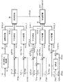
本変形例の制御装置800の詳細構成について図14を用いて説明する。図14では、「出力増大運転」を行う際に、制御装置800において、第2高圧給水加熱器32aに供給される蒸気B1b_2の流量を調整するために、第2の高圧抽気絞り弁V32の開度を制御する部分を代表例として示している。   A detailed configuration of the control device 800 according to the present modification will be described with reference to FIG. In FIG. 14, when performing the “power increase operation”, the control device 800 opens the second high-pressure bleeding throttle valve V32 in order to adjust the flow rate of the steam B1b_2 supplied to the second high-pressure feedwater heater 32a. The part for controlling the degree is shown as a representative example.

図14に示すように、制御装置800は、周波数急減検出器80、蒸気表T80、関数発生器81、PID制御器811〜815、低値選択器82、および、高値選択器83を備えている。   As shown in FIG. 14, the control device 800 includes a frequency drop detector 80, a steam table T80, a function generator 81, PID controllers 811 to 815, a low value selector 82, and a high value selector 83. .

周波数急減検出器80は、図14に示すように、外部から系統周波数の検出値Sfが入力信号として入力される。周波数急減検出器80は、予め規定されている系統周波数の設定値から、入力された系統周波数の検出値Sfを差し引いた値を求める。そして、周波数急減検出器80は、その差し引いた値が閾値よりも大きい場合に、その差し引いた値に応じた出力増指令値S0を出力する。   As shown in FIG. 14, the frequency sudden decrease detector 80 receives the detection value Sf of the system frequency from the outside as an input signal. The frequency sudden decrease detector 80 obtains a value obtained by subtracting the input detection value Sf of the system frequency from the preset value of the system frequency. Then, when the subtracted value is larger than the threshold value, the frequency sudden decrease detector 80 outputs the output increase command value S0 according to the subtracted value.

関数発生器81は、図14に示すように、周波数急減検出器80から出力増指令値S0が入力信号として入力される。そして、関数発生器81は、その出力増指令値S0に応じた開度指令値SV32_0を出力信号として出力する。ここでは、関数発生器81は、出力増指令値S0に応じて第2の高圧抽気絞り弁V32の開度を減少させる開度指令値SV32_0を出力する。   As shown in FIG. 14, the function generator 81 receives the output increase command value S0 from the sudden drop detector 80 as an input signal. Then, the function generator 81 outputs an opening command value SV32_0 corresponding to the output increase command value S0 as an output signal. Here, the function generator 81 outputs an opening command value SV32_0 for decreasing the opening of the second high-pressure bleed throttle valve V32 according to the output increasing command value S0.

PID制御器811は、図14に示すように、流量計FT32で測定された流量SFT32を用いて算出された算出値ΔSFT32が、入力信号として入力される。具体的には、予め設定した流量上限値SFT_U(抽気配管や給水加熱器の設計で決定される値にマージンを加算した値)から、流量計FT32で測定された流量SFT32を減算することによって、算出値ΔSFT32が求められる。そして、その求めた算出値ΔSFT32が、PID制御器811に入力される。PID制御器811は、その算出値ΔSFT32に応じた開度指令値SV32_1を出力信号として出力する。   As shown in FIG. 14, the PID controller 811 receives, as an input signal, a calculation value ΔSFT32 calculated using the flow rate SFT32 measured by the flowmeter FT32. Specifically, by subtracting the flow rate SFT32 measured by the flow meter FT32 from a preset flow rate upper limit value SFT_U (a value obtained by adding a margin to the value determined by the design of the bleed piping and the feedwater heater), The calculated value ΔSFT32 is obtained. Then, the calculated value ΔSFT32 is input to the PID controller 811. The PID controller 811 outputs an opening command value SV32_1 corresponding to the calculated value ΔSFT32 as an output signal.

たとえば、流量上限値SFT_Uが50kg/sであって、測定された流量SFT32が55kg/sである場合には、PID制御器811に入力される算出値ΔSFT32は、「−5kg/s」となる。PID制御器811は、この算出値ΔSFT32に応じて第2の高圧抽気絞り弁V32の開度を減少させる開度指令値SV32_1を出力する。   For example, when the flow rate upper limit value SFT_U is 50 kg / s and the measured flow rate SFT32 is 55 kg / s, the calculated value ΔSFT32 input to the PID controller 811 is “−5 kg / s”. . The PID controller 811 outputs an opening command value SV32_1 for decreasing the opening of the second high-pressure bleed throttle valve V32 according to the calculated value ΔSFT32.

PID制御器812は、図14に示すように、レベル計LT32aで測定された水位SLT32aを用いて算出された算出値ΔSLT32a_Uが、入力信号として入力される。具体的には、予め設定した水位上限値SLT_U(機器の設計で決定される値にマージンを加算した値)から、レベル計LT32aで測定された水位SLT32aを減算することによって、算出値ΔSLT32a_Uが求められる。そして、その求めた算出値ΔSLT32a_Uが、PID制御器812に入力される。PID制御器812は、その算出値ΔSLT32a_Uに応じた開度指令値SV32_2を出力信号として出力する。   As shown in FIG. 14, the PID controller 812 receives, as an input signal, a calculated value ΔSLT32a_U calculated using the water level SLT32a measured by the level meter LT32a. Specifically, the calculated value ΔSLT32a_U is obtained by subtracting the water level SLT32a measured by the level meter LT32a from the preset water level upper limit value SLT_U (the value obtained by adding a margin to the value determined by the design of the device). Can be Then, the calculated value ΔSLT32a_U is input to the PID controller 812. The PID controller 812 outputs an opening command value SV32_2 corresponding to the calculated value ΔSLT32a_U as an output signal.

たとえば、水位上限値SLT_Uが「+10mm」であって、測定された水位SLT32aが「+12mm」である場合には、PID制御器812に入力される算出値ΔSLT32a_Uは、「−2mm」となる。PID制御器812は、この算出値ΔSLT32a_Uに応じて第2の高圧抽気絞り弁V32の開度を減少させる開度指令値SV32_2を出力する。   For example, when the water level upper limit SLT_U is “+10 mm” and the measured water level SLT 32 a is “+12 mm”, the calculated value ΔSLT32a_U input to the PID controller 812 is “−2 mm”. The PID controller 812 outputs an opening command value SV32_2 for decreasing the opening of the second high-pressure bleed throttle valve V32 according to the calculated value ΔSLT32a_U.

PID制御器813は、図14に示すように、給水温度計T31aで検出された温度ST31aと、給水温度計T32aで検出された温度ST32aとを用いて算出された算出値ΔST31a_2が、入力信号として入力される。具体的には、給水温度計T31aで検出された温度ST31aから、給水温度計T32aで検出された温度ST32aを減算することによって、温度差ΔST31aが求められる。この温度差ΔST31aは、第1高圧給水加熱器31aにおいて入口に供給される水F32aの温度と出口から排出される水F31aの温度との温度差である。そして、その温度差について予め設定した温度差上限値ΔST_U1(機器の設計から決定された値にマージンを加算した値)から、上記のように算出した温度差ΔST31aを減算することによって、差分値ΔST31a_1が求められる。その後、その差分値ΔST31a_1に「−1」を積算して正負を反転させることで、算出値ΔST31a_2が求められる。そして、その求めた算出値ΔST31a_2が、PID制御器813に入力される。PID制御器813は、その算出値ΔST31a_2に応じた開度指令値SV32_3を出力信号として出力する。   As shown in FIG. 14, the PID controller 813 outputs, as an input signal, a calculated value ΔST31a_2 calculated using the temperature ST31a detected by the feedwater thermometer T31a and the temperature ST32a detected by the feedwater thermometer T32a. Will be entered. Specifically, the temperature difference ΔST31a is obtained by subtracting the temperature ST32a detected by the feedwater thermometer T32a from the temperature ST31a detected by the feedwater thermometer T31a. The temperature difference ΔST31a is a temperature difference between the temperature of the water F32a supplied to the inlet and the temperature of the water F31a discharged from the outlet in the first high-pressure feedwater heater 31a. Then, the difference value ΔST31a_1 is calculated by subtracting the temperature difference ΔST31a calculated as described above from the temperature difference upper limit value ΔST_U1 (a value obtained by adding a margin to the value determined from the device design) preset for the temperature difference. Is required. Thereafter, the difference value ΔST31a_1 is multiplied by “−1” and the sign is inverted to obtain a calculated value ΔST31a_2. Then, the calculated value ΔST31a_2 is input to the PID controller 813. The PID controller 813 outputs an opening command value SV32_3 corresponding to the calculated value ΔST31a_2 as an output signal.

たとえば、温度差上限値ΔST_U1が20℃であって、温度差ΔST31aが22℃である場合には、PID制御器813に入力される算出値ΔST31a_2は、「+2℃」となる。PID制御器813は、この算出値ΔST31a_2に応じて第2の高圧抽気絞り弁V32の開度を増加させる開度指令値SV32_3を出力する。   For example, when temperature difference upper limit ΔST_U1 is 20 ° C. and temperature difference ΔST31a is 22 ° C., calculated value ΔST31a_2 input to PID controller 813 is “+ 2 ° C.”. The PID controller 813 outputs an opening command value SV32_3 for increasing the opening of the second high-pressure bleeding throttle valve V32 according to the calculated value ΔST31a_2.

PID制御器814は、図14に示すように、レベル計LT32aで測定された水位SLT32aを用いて算出された算出値ΔSLT32a_Lが、入力信号として入力される。具体的には、予め設定した水位下限値SLT_L(機器の設計で決定される値にマージンを加算した値)から、レベル計LT32aで測定された水位SLT32aを減算することによって、算出値ΔSLT32a_Lが求められる。そして、その求めた算出値ΔSLT32a_Lが、PID制御器814に入力される。PID制御器814は、その算出値ΔSLT32a_Lに応じた開度指令値SV32_4を出力信号として出力する。   As shown in FIG. 14, the PID controller 814 receives, as an input signal, a calculation value ΔSLT32a_L calculated using the water level SLT32a measured by the level meter LT32a. Specifically, the calculated value ΔSLT32a_L is obtained by subtracting the water level SLT32a measured by the level meter LT32a from a preset water level lower limit value SLT_L (a value obtained by adding a margin to the value determined by the design of the device). Can be Then, the calculated value ΔSLT32a_L is input to the PID controller 814. The PID controller 814 outputs an opening command value SV32_4 corresponding to the calculated value ΔSLT32a_L as an output signal.

たとえば、水位下限値SLT_Lが「−10mm」であって、測定された水位SLT32aが「−12mm」である場合には、PID制御器814に入力される算出値ΔSLT32a_Lは、「+2mm」となる。PID制御器814は、この算出値ΔSLT32a_Lに応じて第2の高圧抽気絞り弁V32の開度を増加させる開度指令値SV32_4を出力する。   For example, when the water level lower limit SLT_L is “−10 mm” and the measured water level SLT 32 a is “−12 mm”, the calculated value ΔSLT32a_L input to the PID controller 814 is “+2 mm”. The PID controller 814 outputs an opening command value SV32_4 for increasing the opening of the second high-pressure bleed throttle valve V32 according to the calculated value ΔSLT32a_L.

PID制御器815は、図14に示すように、ドレン水温度計X32aで検出された温度SX32aと、圧力計P32aで検出された圧力SP32aとを用いて算出された算出値ΔSC32aが入力信号として入力される。具体的には、ルックアップテーブル等で構成された蒸気表T80を用いて、圧力計P32aで検出された圧力SP32aに対応する飽和蒸気温度SS32aが求められる。そして、その求めた飽和蒸気温度SS32aから、ドレン水温度計X32aで検出された温度SX32aを減算することによって、温度差ΔSX32aが求められる。そして、その温度差について予め設定した温度差下限値ΔSC_L2(サブクール温度下限値)から、上記のように算出した温度差ΔSX32aを減算することによって、算出値ΔSC32aが求められる。そして、その求めた算出値ΔSC32aが、PID制御器815に入力される。PID制御器815は、その算出値ΔSC32aに応じた開度指令値SV32_5を出力信号として出力する。   As shown in FIG. 14, the PID controller 815 receives, as an input signal, a calculation value ΔSC32a calculated using the temperature SX32a detected by the drain water thermometer X32a and the pressure SP32a detected by the pressure gauge P32a. Is done. Specifically, the saturated steam temperature SS32a corresponding to the pressure SP32a detected by the pressure gauge P32a is obtained using a steam table T80 configured by a look-up table or the like. Then, the temperature difference ΔSX32a is obtained by subtracting the temperature SX32a detected by the drain water thermometer X32a from the obtained saturated steam temperature SS32a. Then, the calculated value ΔSC32a is obtained by subtracting the temperature difference ΔSX32a calculated as described above from the temperature difference lower limit value ΔSC_L2 (subcool temperature lower limit value) preset for the temperature difference. Then, the calculated value ΔSC32a is input to the PID controller 815. The PID controller 815 outputs an opening command value SV32_5 corresponding to the calculated value ΔSC32a as an output signal.

たとえば、温度差下限値ΔSC_L2(サブクール温度下限値)が5℃であって、温度差ΔSX32aが3℃である場合には、PID制御器815に入力される算出値ΔSC32aは、「+2℃」となる。PID制御器815は、この算出値ΔSC32aに応じて第2の高圧抽気絞り弁V32の開度を増加させる開度指令値SV32_5を出力する。   For example, when the temperature difference lower limit ΔSC_L2 (subcool temperature lower limit) is 5 ° C. and the temperature difference ΔSX32a is 3 ° C., the calculated value ΔSC32a input to the PID controller 815 is “+ 2 ° C.” Become. The PID controller 815 outputs an opening command value SV32_5 for increasing the opening of the second high-pressure bleed throttle valve V32 according to the calculated value ΔSC32a.

低値選択器82は、図14に示すように、関数発生器81が出力した開度指令値SV32_0とPID制御器811が出力した開度指令値SV32_1とPID制御器812が出力した開度指令値SV32_2とが入力信号として入力される。低値選択器82は、関数発生器81が出力した開度指令値SV32_0とPID制御器811が出力した開度指令値SV32_1とPID制御器812が出力した開度指令値SV32_2とのうち最も低い値を選択する。そして、低値選択器82は、その選択した開度指令値SV32Lを高値選択器83に出力信号として出力する。   As shown in FIG. 14, the low value selector 82 includes an opening command value SV32_1 output from the function generator 81, an opening command value SV32_1 output from the PID controller 811 and an opening command SV output from the PID controller 812. The value SV32_2 is input as an input signal. The low value selector 82 is the lowest among the opening command value SV32_0 output by the function generator 81, the opening command value SV32_1 output by the PID controller 811 and the opening command value SV32_2 output by the PID controller 812. Select a value. Then, the low value selector 82 outputs the selected opening command value SV32L to the high value selector 83 as an output signal.

高値選択器83は、図14に示すように、低値選択器82が出力した開度指令値SV32Lと、PID制御器813が出力した開度指令値SV32_3と、PID制御器814が出力した開度指令値SV32_4と、PID制御器815が出力した開度指令値SV32_5とが入力信号として入力される。高値選択器83は、低値選択器82が出力した開度指令値SV32Lと、PID制御器813が出力した開度指令値SV32_3と、PID制御器814が出力した開度指令値SV32_4と、PID制御器815が出力した開度指令値SV32_5とのうち最も高い値を選択する。そして、高値選択器83は、その選択した開度指令値SV32を第2の高圧抽気絞り弁V32に出力信号として出力する。   As shown in FIG. 14, the high value selector 83 includes an opening command value SV32L output by the low value selector 82, an opening command value SV32_3 output by the PID controller 813, and an opening command value output by the PID controller 814. The degree command value SV32_4 and the opening degree command value SV32_5 output from the PID controller 815 are input as input signals. The high value selector 83 includes an opening command value SV32L output from the low value selector 82, an opening command value SV32_3 output from the PID controller 813, an opening command value SV32_4 output from the PID controller 814, and a PID. The highest value is selected from the opening command value SV32_5 output by the controller 815. Then, the high value selector 83 outputs the selected opening command value SV32 to the second high-pressure bleeding throttle valve V32 as an output signal.

なお、図示を省略しているが、制御装置800は、第2高圧給水加熱器32bに供給される蒸気B1b_2の流量を調整するために、上記のPID制御器811〜815と同様なPID制御器を更に備えている。また、制御装置800において、第2の高圧抽気絞り弁V32以外の抽気絞り弁の動作を制御する部分についても、上記と同様に構成されている。   Although not shown, the control device 800 adjusts the flow rate of the steam B1b_2 supplied to the second high-pressure feed water heater 32b by using a PID controller similar to the PID controllers 811 to 815 described above. Is further provided. Also, in the control device 800, a portion that controls the operation of the bleed throttle valve other than the second high-pressure bleed throttle valve V32 is configured in the same manner as described above.

本変形例において、上記の「出力増大運転」を実行するときの動作の一例に関して説明する。   In the present modified example, an example of the operation when executing the above “power increase operation” will be described.

本変形例において、「出力増大運転」を実行しているときには、上記した第2実施形態の場合と同様に、給水加熱器31a〜33a,31b〜33bにおいて計測したドレン水の温度および内部の圧力に基づいて、制御装置800が抽気絞り弁V31〜V33の動作を制御する。このため、給水加熱部3においてドレンフラッシュが発生することを効果的に防止可能である。   In this modified example, when the “power increase operation” is being executed, the temperature of the drain water and the internal pressure measured in the feed water heaters 31a to 33a and 31b to 33b are the same as in the above-described second embodiment. , The control device 800 controls the operation of the bleed throttle valves V31 to V33. Therefore, it is possible to effectively prevent the drain flush from occurring in the feed water heating unit 3.

そして、本変形例では、上記した第2実施形態の場合と異なり、流量計FT31〜FT33が得た流量データに基づいて、制御装置800が抽気絞り弁V31〜V33の動作を制御する。ここでは、流量計FT31〜FT33が得た流量データに基づいて、給水加熱器31a〜33a,31b〜33bに加熱媒体として供給される蒸気B1a,B1b_2,B1c(抽気蒸気)の流量が、予め設定した上限値以下であるか否かを、制御装置800が判断する。流量が上限値を超える場合には、制御装置800は、抽気絞り弁V31〜V33の開度を閉じる。これに対して、流量が上限値以下である場合には、制御装置800は、抽気絞り弁V31〜V33の開度を保持する。このため、給水加熱器31a〜33a,31b〜33bに加熱媒体として供給される蒸気B1a,B1b_2,B1c(抽気蒸気)の流量を上限値以下に調整することができる。   Then, in the present modified example, unlike the case of the above-described second embodiment, the control device 800 controls the operation of the bleeding throttle valves V31 to V33 based on the flow rate data obtained by the flow meters FT31 to FT33. Here, based on the flow rate data obtained by the flow meters FT31 to FT33, the flow rates of the steams B1a, B1b_2, and B1c (extracted steam) supplied as the heating medium to the feed water heaters 31a to 33a, 31b to 33b are set in advance. The control device 800 determines whether or not the value is equal to or less than the upper limit. When the flow rate exceeds the upper limit value, control device 800 closes the opening of bleeding throttle valves V31 to V33. On the other hand, when the flow rate is equal to or less than the upper limit value, the control device 800 holds the opening degrees of the bleeding throttle valves V31 to V33. Therefore, the flow rates of the steams B1a, B1b_2, and B1c (extracted steam) supplied as heating media to the feedwater heaters 31a to 33a and 31b to 33b can be adjusted to be equal to or less than the upper limit value.

また、本変形例では、上記した第2実施形態の場合と異なり、レベル計LT31a〜LT33a,LT31b〜LT33bが得た水位データに基づいて、抽気絞り弁V31〜V33の動作を制御する。ここでは、レベル計LT31a〜LT33a,LT31b〜LT33bが得た水位データに基づいて、給水加熱器31a〜33a,31b〜33bの内部に存在するドレン水の水位が、予め設定した上限値と下限値との範囲内にあるか否かを、制御装置800が判断する。ドレン水の水位が上限値を超える場合には、制御装置800は、抽気絞り弁V31〜V33の開度を閉じる。ドレン水の水位が下限値未満である場合には、制御装置800は、抽気絞り弁V31〜V33の開度を開ける。これに対して、ドレン水の水位が上限値と下限値との範囲内である場合には、制御装置800は、抽気絞り弁V31〜V33の開度を保持する。このため、ドレン水の水位を上限値と下限値とで規定された範囲内に調整することができる。   Further, in the present modified example, unlike the case of the above-described second embodiment, the operation of the bleed throttle valves V31 to V33 is controlled based on the water level data obtained by the level meters LT31a to LT33a and LT31b to LT33b. Here, based on the water level data obtained by the level meters LT31a to LT33a, LT31b to LT33b, the water level of the drain water present inside the feed water heaters 31a to 33a, 31b to 33b is set to a preset upper limit value and lower limit value. The control device 800 determines whether or not the range is within the range. When the water level of the drain water exceeds the upper limit, the control device 800 closes the opening of the bleeding throttle valves V31 to V33. When the level of the drain water is lower than the lower limit, the control device 800 opens the bleeding throttle valves V31 to V33. On the other hand, when the level of the drain water is within the range between the upper limit value and the lower limit value, control device 800 holds the opening degree of bleeding throttle valves V31 to V33. For this reason, the level of the drain water can be adjusted within the range defined by the upper limit and the lower limit.

更に、本変形例では、上記した第1実施形態の場合と同様に、給水温度計T31a〜T33a,T31b〜T33bが得た温度データに基づいて、抽気絞り弁V31〜V33の動作を制御する。ここでは、給水温度計T31a〜T33a,T31b〜T33bが得た温度データに基づいて、給水加熱器31a〜33a,31b〜33bにおいて流入する水の温度と流出する水の温度との温度差を、制御装置800が算出する。そして、その温度差の算出値が、温度差について予め設定した上限値を超えるか否かを制御装置800が判断する。そして、その温度差の算出値が上限値を超える場合には、制御装置800は、抽気絞り弁V31〜V33の開度を調整する。これに対して、温度差の算出値が予め設定した上限値以下である場合には、制御装置800は、抽気絞り弁V31〜V33の開度を保持する。このため、給水加熱器31a〜33a,31b〜33bの温度差を上限値以下にすることができるので、給水加熱器31a〜33a,31b〜33bの破損を効果的に防止可能である。   Further, in the present modified example, the operation of the bleeding throttle valves V31 to V33 is controlled based on the temperature data obtained by the feedwater thermometers T31a to T33a and T31b to T33b, as in the case of the above-described first embodiment. Here, based on the temperature data obtained by the feedwater thermometers T31a to T33a and T31b to T33b, the temperature difference between the temperature of the water flowing in and the temperature of the flowing water in the feedwater heaters 31a to 33a and 31b to 33b is calculated as follows. The control device 800 calculates. Then, control device 800 determines whether or not the calculated value of the temperature difference exceeds a preset upper limit value for the temperature difference. If the calculated value of the temperature difference exceeds the upper limit, control device 800 adjusts the opening of bleed throttle valves V31 to V33. On the other hand, when the calculated value of the temperature difference is equal to or smaller than the preset upper limit, the control device 800 holds the opening degrees of the bleed throttle valves V31 to V33. For this reason, the temperature difference between the feed water heaters 31a to 33a and 31b to 33b can be made equal to or less than the upper limit value, so that breakage of the feed water heaters 31a to 33a and 31b to 33b can be effectively prevented.

<その他>
本発明のいくつかの実施形態を説明したが、これらの実施形態は、例として提示したものであり、発明の範囲を限定することは意図していない。これら新規な実施形態は、その他の様々な形態で実施されることが可能であり、発明の要旨を逸脱しない範囲で、種々の省略、置き換え、変更を行うことができる。これら実施形態やその変形は、発明の範囲や要旨に含まれるとともに、特許請求の範囲に記載された発明とその均等の範囲に含まれる。
<Others>
While some embodiments of the invention have been described, these embodiments have been presented by way of example only, and are not intended to limit the scope of the inventions. These new embodiments can be implemented in other various forms, and various omissions, replacements, and changes can be made without departing from the spirit of the invention. These embodiments and their modifications are included in the scope and gist of the invention, and are also included in the invention described in the claims and their equivalents.

1…蒸気タービン、2…復水器、3…給水加熱部、4…ボイラ、11…高圧タービン部、12…中圧タービン部、13…低圧タービン部、14…発電機、31(31a,31b)…第1高圧給水加熱器(給水加熱器)、32(32a,32b)…第2高圧給水加熱器(給水加熱器)、33(33a,33b)…第3高圧給水加熱器(給水加熱器)、34…第1低圧給水加熱器(給水加熱器)、35…第2低圧給水加熱器(給水加熱器)、300…弁ケーシング、300A…入口、300B…出口、310…弁体、310S…ストッパ、311…脱気器、320…弁棒、330…駆動装置、800…制御装置、81…関数発生器、811〜815…PID制御器、82…低値選択器、83…高値選択器、FT31〜FT33…流量計、LT31a〜LT33a,LT31b〜LT33b…レベル計、P2…復水ポンプ、P311…給水ポンプ、P31a,P31b,P32a,P32b,P33a,P33b,P34,P35…圧力計、T2,T311a,T311b,T31a,T31b,T32a,T32b,T33a,T33b,T34,T35…給水温度計、V31,V31a,V31b…第1の高圧抽気絞り弁(抽気絞り弁)、V32,V32a,V32b…第2の高圧抽気絞り弁(抽気絞り弁)、V33,V33a,V33b…第3の高圧抽気絞り弁(抽気絞り弁)、V34…第1の低圧抽気絞り弁(抽気絞り弁)、V35…第2の低圧抽気絞り弁(抽気絞り弁)、X31a,X31b,X32a,X32b,X33a,X33b,X34,X35…ドレン水温度計、80…周波数急減検出器80、T80…蒸気表 DESCRIPTION OF SYMBOLS 1 ... Steam turbine, 2 ... Condenser, 3 ... Feed water heating part, 4 ... Boiler, 11 ... High pressure turbine part, 12 ... Medium pressure turbine part, 13 ... Low pressure turbine part, 14 ... Generator, 31 (31a, 31b) ) ... first high pressure feed water heater (feed water heater), 32 (32a, 32b) ... second high pressure feed water heater (feed water heater), 33 (33a, 33b) ... third high pressure feed water heater (feed water heater) ), 34: first low-pressure feedwater heater (feedwater heater), 35: second low-pressure feedwater heater (feedwater heater), 300: valve casing, 300A ... inlet, 300B ... outlet, 310 ... valve body, 310S ... Stopper, 311 deaerator, 320 valve stem, 330 driving device, 800 control device, 81 function generator, 811 to 815 PID controller, 82 low value selector, 83 high value selector, FT31 to FT33: Flow meter, LT31 LT33a, LT31b to LT33b: Level gauge, P2: Condenser pump, P311: Water supply pump, P31a, P31b, P32a, P32b, P33a, P33b, P34, P35: Pressure gauge, T2, T311a, T311b, T31a, T31b, T32a, T32b, T33a, T33b, T34, T35: water supply thermometer, V31, V31a, V31b: first high-pressure bleed throttle valve (bleed throttle valve), V32, V32a, V32b: second high-pressure bleed throttle valve (bleed air) V33, V33a, V33b: third high-pressure bleed throttle valve (bleed throttle valve), V34: first low-pressure bleed throttle valve (bleed throttle valve), V35: second low-pressure bleed throttle valve (bleed throttle) Valves), X31a, X31b, X32a, X32b, X33a, X33b, X34, X35 ... Drain water thermometer, 8 ... Frequency sudden decrease detector 80, T80 ... steam tables

Claims (10)

蒸気タービンと、
前記蒸気タービンから排気された蒸気を冷却して凝縮させる復水器と、
前記蒸気タービンから抽気された蒸気を加熱媒体として用いて、前記復水器において凝縮された水を加熱する給水加熱部と、
前記給水加熱部において加熱された水を加熱することによって蒸気を生成するボイラと、
前記ボイラで生成された蒸気が前記蒸気タービンに供給されることによって駆動し、発電を行う発電機と
を備え、前記発電機で発電された電力が電力系統に出力される火力発電プラントであって、
前記給水加熱部に供給される前記加熱媒体の流量を調整する抽気絞り弁と、
前記抽気絞り弁の動作を制御する制御装置と
を有し、
前記制御装置は、通常運転の場合には前記抽気絞り弁の開度を所定量に調整し、
前記電力系統における系統周波数の減少を検出した時には、前記給水加熱部に供給される前記加熱媒体の流量を前記通常運転の場合よりも低減するように、前記抽気絞り弁の開度を前記所定量より小さくすることによって、前記発電機の出力を前記通常運転の場合に比べて増加させる出力増大運転を行うとともに、前記出力増大運転を実行しているときには、前記給水加熱部を流れる水の温度に基づいて、前記抽気絞り弁の動作を制御する、
火力発電プラント。
A steam turbine,
A condenser for cooling and condensing the steam exhausted from the steam turbine,
Using a steam extracted from the steam turbine as a heating medium, a feedwater heating unit that heats water condensed in the condenser,
A boiler that generates steam by heating water heated in the feedwater heating unit,
A generator that is driven by the steam generated by the boiler being supplied to the steam turbine to generate power, wherein the power generated by the generator is output to a power system. ,
A bleed throttle valve that adjusts the flow rate of the heating medium supplied to the feedwater heating unit,
A control device for controlling the operation of the bleeding throttle valve,
The control device adjusts the opening of the bleed throttle valve to a predetermined amount during normal operation,
When detecting a decrease in system frequency in the power system, the opening degree of the bleed throttle valve is set to the predetermined amount so that the flow rate of the heating medium supplied to the feedwater heating unit is reduced as compared with the case of the normal operation. By making the output smaller, the output of the generator is increased compared to the case of the normal operation, and the output increasing operation is performed.When the output increasing operation is performed, the temperature of the water flowing through the feedwater heating unit is reduced. Controlling the operation of the bleed throttle valve based on
Thermal power plant.
前記給水加熱部は、
複数の給水加熱器
を備え、
前記複数の給水加熱器のそれぞれに供給される前記加熱媒体の圧力が、前記復水器で凝縮した水の流れに沿って順次高くなるように構成され、かつ、前記復水器で凝縮した水が前記複数の給水加熱器を順次流れることによって、前記復水器で凝縮した水の温度が上昇するように前記複数の給水加熱器は多段階に構成されており、
前記抽気絞り弁は、複数であって、前記多段階の給水加熱器の各段に設けられており、
前記制御装置は、
前記出力増大運転を開始するときには、前記複数の抽気絞り弁のうち少なくとも1つを閉じ、
前記出力増大運転を実行しているときには、前記複数の給水加熱器のそれぞれにおいて流入する水の温度と流出する水の温度との温度差を算出し、当該算出した温度差の算出値が、予め設定した上限値を超えるか否かを判断し、前記算出値が前記上限値を超える場合には、前記上限値を超えた給水加熱器の上流に位置する給水加熱器への前記加熱媒体の流量を調整するための抽気絞り弁を開ける、
請求項1に記載の火力発電プラント。
The feedwater heating unit,
With multiple feedwater heaters,
The pressure of the heating medium supplied to each of the plurality of feed water heaters is configured to increase sequentially along the flow of the water condensed by the condenser, and the water condensed by the condenser By sequentially flowing through the plurality of feed water heaters, the plurality of feed water heaters are configured in multiple stages so that the temperature of water condensed in the condenser rises,
The bleeding throttle valve is plural, and is provided at each stage of the multi-stage feed water heater,
The control device includes:
When starting the output increase operation, at least one of the plurality of bleeding throttle valves is closed,
When performing the output increase operation, the temperature difference between the temperature of the inflowing water and the temperature of the outflowing water in each of the plurality of feedwater heaters is calculated, and the calculated value of the calculated temperature difference is calculated in advance. Determine whether or not exceeds the set upper limit, if the calculated value exceeds the upper limit, the flow rate of the heating medium to the feed water heater located upstream of the feed water heater exceeded the upper limit Open the bleed throttle valve to adjust the
The thermal power plant according to claim 1.
前記給水加熱部は、
第1給水加熱器と、
前記加熱媒体の圧力が前記第1給水加熱器よりも低い第2給水加熱器と
を前記給水加熱器として含み、前記復水器で凝縮した水が、前記第2給水加熱器と前記第1給水加熱器とを順次流れることによって温度が上昇するように構成されており、
前記抽気絞り弁は、
前記第1給水加熱器に前記加熱媒体の流量を調整する第1の抽気絞り弁と、
前記第2給水加熱器に前記加熱媒体の流量を調整する第2の抽気絞り弁と
を少なくとも含み、
前記制御装置は、
前記出力増大運転を開始するときには、前記第2の抽気絞り弁を閉じ、
前記出力増大運転を実行しているときには、前記第1給水加熱器に流入する水の温度と前記第1給水加熱器から流出する水の温度との温度差を算出し、当該算出した温度差の算出値が、予め設定した上限値を超えるか否かを判断し、前記算出値が前記上限値を超える場合には、前記第2の抽気絞り弁を開ける、
請求項2に記載の火力発電プラント。
The feedwater heating unit,
A first feed water heater,
A second feedwater heater having a pressure of the heating medium lower than that of the first feedwater heater, wherein the water condensed in the condenser includes the second feedwater heater and the first feedwater. It is configured so that the temperature rises by sequentially flowing through the heater,
The bleeding throttle valve,
A first bleeding throttle valve for adjusting the flow rate of the heating medium to the first feedwater heater;
A second bleeding throttle valve for adjusting the flow rate of the heating medium in the second feedwater heater,
The control device includes:
When starting the output increase operation, the second bleed throttle valve is closed,
When performing the output increase operation, a temperature difference between the temperature of the water flowing into the first feedwater heater and the temperature of the water flowing out of the first feedwater heater is calculated, and the calculated temperature difference is calculated. It is determined whether the calculated value exceeds a preset upper limit value, and when the calculated value exceeds the upper limit value, the second bleed throttle valve is opened,
The thermal power plant according to claim 2.
前記給水加熱部は、
高圧給水加熱部と、
前記加熱媒体の圧力が前記高圧給水加熱部よりも低い低圧給水加熱部と
を含み、前記復水器で凝縮した水が、前記低圧給水加熱部と前記高圧給水加熱部とを順次流れることによって温度が上昇するように構成されており、
前記第1給水加熱器、および、前記第2給水加熱器は、前記高圧給水加熱部を構成する、
請求項3に記載の火力発電プラント。
The feedwater heating unit,
High pressure feed water heating section,
A low-pressure feedwater heating unit in which the pressure of the heating medium is lower than the high-pressure feedwater heating unit, wherein the water condensed in the condenser sequentially flows through the low-pressure feedwater heating unit and the high-pressure feedwater heating unit. Is configured to rise,
The first feedwater heater, and the second feedwater heater constitute the high-pressure feedwater heating unit,
The thermal power plant according to claim 3.
前記給水加熱部は、
高圧給水加熱部と、
前記加熱媒体の圧力が前記高圧給水加熱部よりも低い低圧給水加熱部と
を含み、前記復水器で凝縮した水が、前記低圧給水加熱部と前記高圧給水加熱部とを順次流れることによって温度が上昇するように構成されており、
前記第1給水加熱器、および、前記第2給水加熱器は、前記低圧給水加熱部を構成する、
請求項3に記載の火力発電プラント。
The feedwater heating unit,
High pressure feed water heating section,
A low-pressure feedwater heating unit in which the pressure of the heating medium is lower than the high-pressure feedwater heating unit, wherein the water condensed in the condenser sequentially flows through the low-pressure feedwater heating unit and the high-pressure feedwater heating unit. Is configured to rise,
The first feedwater heater, and the second feedwater heater constitute the low-pressure feedwater heating unit,
The thermal power plant according to claim 3.
蒸気タービンと、
前記蒸気タービンから排気された蒸気を冷却して凝縮させる復水器と、
前記蒸気タービンから抽気された蒸気を加熱媒体として用いて、前記復水器において凝縮された水を加熱する給水加熱部と、
前記給水加熱部において加熱された水を加熱することによって蒸気を生成するボイラと、
前記ボイラで生成された蒸気が前記蒸気タービンに供給されることによって駆動し、発電を行う発電機と
を備え、前記発電機で発電された電力が電力系統に出力される火力発電プラントであって、
前記給水加熱部に供給される前記加熱媒体の流量を調整する抽気絞り弁と、
前記抽気絞り弁の動作を制御する制御装置と
を有し、
前記制御装置は、前記電力系統において系統周波数が減少したときには、前記給水加熱部において前記加熱媒体が供給される内部の温度が前記加熱媒体の飽和温度より低い状態となる範囲で、前記出力増大運転が開始されてから前記抽気絞り弁をどの順序でどの程度開けるかを決めた予め定められた手順を有し、
前記予め定められた手順で前記抽気絞り弁の開度を調整することによって、前記給水加熱部に供給する前記加熱媒体の流量を通常運転の場合よりも低減させて、前記発電機の出力を前記通常運転の場合よりも増加させる出力増大運転を行う、
火力発電プラント。
A steam turbine,
A condenser for cooling and condensing the steam exhausted from the steam turbine,
A feedwater heating unit that heats water condensed in the condenser, using steam extracted from the steam turbine as a heating medium,
A boiler that generates steam by heating water heated in the feedwater heating unit,
A generator that is driven by the steam generated by the boiler being supplied to the steam turbine to generate power, and wherein the power generated by the generator is output to a power system. ,
A bleeding throttle valve for adjusting the flow rate of the heating medium supplied to the feedwater heating unit,
A control device for controlling the operation of the bleeding throttle valve,
The control device, when the system frequency is reduced in the power system, the output increase operation in a range in which the temperature inside the supply of the heating medium is lower than the saturation temperature of the heating medium in the feedwater heating unit. Has a predetermined procedure to determine in which order and how much to open the bleeding throttle valve since the start,
By adjusting the opening of the bleeding throttle valve in the predetermined procedure, the flow rate of the heating medium supplied to the feed water heating unit is reduced as compared with the case of normal operation, and the output of the generator is reduced. Perform an output increase operation that increases compared to the case of normal operation.
Thermal power plant.
前記制御装置は、前記出力増大運転を実行しているときには、前記給水加熱部の内部圧力を検出するとともに、と前記給水加熱部において前記加熱媒体が供給される箇所に存在するドレン水の温度を検出し、前記内部の圧力に基づいて前記加熱媒体の飽和温度を求め、前記検出されたドレン水の温度が前記求められた飽和温度より低くなるよう前記抽気絞り弁の動作を制御する、
請求項1に記載の火力発電プラント。
The control device detects the internal pressure of the feed water heating unit and executes the temperature of the drain water present at a location where the heating medium is supplied in the feed water heating unit when the output increasing operation is being performed. Detecting, determining the saturation temperature of the heating medium based on the internal pressure, controlling the operation of the bleed throttle valve so that the detected drain water temperature is lower than the determined saturation temperature,
The thermal power plant according to claim 1.
前記抽気絞り弁は、開度が全閉状態になることを阻害する位置にストッパが設置されている、
請求項6または7に記載の火力発電プラント。
In the bleeding throttle valve, a stopper is provided at a position that prevents the opening degree from being in a fully closed state.
The thermal power plant according to claim 6.
前記制御装置は、
前記出力増大運転を実行しているときには、前記給水加熱部に前記加熱媒体として供給される蒸気の流量、前記給水加熱部において前記加熱媒体が供給される内部に存在するドレン水の水位、前記給水加熱部において被加熱媒体として流れる水の温度の一つ以上に基づいて、前記抽気絞り弁の動作を制御する、
請求項7または8に記載の火力発電プラント。
The control device includes:
When the output increasing operation is being performed, the flow rate of steam supplied to the feedwater heating section as the heating medium, the level of drain water present inside the heating medium supplied to the feedwater heating section, Controlling the operation of the bleed throttle valve based on one or more temperatures of water flowing as a heated medium in the heating unit,
A thermal power plant according to claim 7.
前記抽気絞り弁は、油圧弁である、
請求項1から9のいずれかに記載の火力発電プラント。
The bleeding throttle valve is a hydraulic valve,
The thermal power plant according to any one of claims 1 to 9.
JP2018125951A 2018-07-02 2018-07-02 Thermal power plant Active JP7039403B2 (en)

Priority Applications (1)

Application Number Priority Date Filing Date Title
JP2018125951A JP7039403B2 (en) 2018-07-02 2018-07-02 Thermal power plant

Applications Claiming Priority (1)

Application Number Priority Date Filing Date Title
JP2018125951A JP7039403B2 (en) 2018-07-02 2018-07-02 Thermal power plant

Publications (2)

Publication Number Publication Date
JP2020002931A true JP2020002931A (en) 2020-01-09
JP7039403B2 JP7039403B2 (en) 2022-03-22

Family

ID=69099489

Family Applications (1)

Application Number Title Priority Date Filing Date
JP2018125951A Active JP7039403B2 (en) 2018-07-02 2018-07-02 Thermal power plant

Country Status (1)

Country Link
JP (1) JP7039403B2 (en)

Cited By (2)

* Cited by examiner, † Cited by third party
Publication number Priority date Publication date Assignee Title
JP2021116687A (en) * 2020-01-22 2021-08-10 三菱パワー株式会社 Output command device and output command method
WO2025081717A1 (en) * 2023-10-16 2025-04-24 浙江省白马湖实验室有限公司 Efficient operation regulation and control system and method for deep peak shaving of thermal power generating unit by means of using variable steam turbine rotating speeds

Citations (8)

* Cited by examiner, † Cited by third party
Publication number Priority date Publication date Assignee Title
JPS52151202U (en) * 1976-05-14 1977-11-16
JPS5840405A (en) * 1981-09-04 1983-03-09 株式会社日立製作所 Method and device for controlling water level of drain in feedwater heater
DE102005034847A1 (en) * 2005-07-26 2007-02-08 Steag Saar Energie Ag Steam power station comprises switching units intended for switching off the last high-pressure preheater in front of the steam generator within the framework of primary regulation of the mains frequency
EP2351914A1 (en) * 2010-01-11 2011-08-03 Alstom Technology Ltd Power plant and method of operating a power plant
JP2011190696A (en) * 2010-03-12 2011-09-29 Hitachi Ltd Coal-fired power plant, and method for operating coal-fired power plant
JP2014066188A (en) * 2012-09-26 2014-04-17 Hitachi Ltd Steam turbine power generation facility and operation method thereof
CN106150575A (en) * 2016-08-12 2016-11-23 浙江浙能技术研究院有限公司 A kind of tackle the anxious steam turbine fallen of mains frequency and meet an urgent need application of load device and method
JP2017166722A (en) * 2016-03-14 2017-09-21 株式会社東芝 Method for operating power-generating plant

Family Cites Families (1)

* Cited by examiner, † Cited by third party
Publication number Priority date Publication date Assignee Title
US20030182944A1 (en) 2002-04-02 2003-10-02 Hoffman John S. Highly supercharged gas-turbine generating system

Patent Citations (8)

* Cited by examiner, † Cited by third party
Publication number Priority date Publication date Assignee Title
JPS52151202U (en) * 1976-05-14 1977-11-16
JPS5840405A (en) * 1981-09-04 1983-03-09 株式会社日立製作所 Method and device for controlling water level of drain in feedwater heater
DE102005034847A1 (en) * 2005-07-26 2007-02-08 Steag Saar Energie Ag Steam power station comprises switching units intended for switching off the last high-pressure preheater in front of the steam generator within the framework of primary regulation of the mains frequency
EP2351914A1 (en) * 2010-01-11 2011-08-03 Alstom Technology Ltd Power plant and method of operating a power plant
JP2011190696A (en) * 2010-03-12 2011-09-29 Hitachi Ltd Coal-fired power plant, and method for operating coal-fired power plant
JP2014066188A (en) * 2012-09-26 2014-04-17 Hitachi Ltd Steam turbine power generation facility and operation method thereof
JP2017166722A (en) * 2016-03-14 2017-09-21 株式会社東芝 Method for operating power-generating plant
CN106150575A (en) * 2016-08-12 2016-11-23 浙江浙能技术研究院有限公司 A kind of tackle the anxious steam turbine fallen of mains frequency and meet an urgent need application of load device and method

Cited By (3)

* Cited by examiner, † Cited by third party
Publication number Priority date Publication date Assignee Title
JP2021116687A (en) * 2020-01-22 2021-08-10 三菱パワー株式会社 Output command device and output command method
JP7288867B2 (en) 2020-01-22 2023-06-08 三菱重工業株式会社 Output command device and output command method
WO2025081717A1 (en) * 2023-10-16 2025-04-24 浙江省白马湖实验室有限公司 Efficient operation regulation and control system and method for deep peak shaving of thermal power generating unit by means of using variable steam turbine rotating speeds

Also Published As

Publication number Publication date
JP7039403B2 (en) 2022-03-22

Similar Documents

Publication Publication Date Title
US9074494B2 (en) System and apparatus for controlling temperature in a heat recovery steam generator
JP6352762B2 (en) Control device and activation method
JP6264128B2 (en) Combined cycle plant, control method thereof, and control device thereof
RU2586802C2 (en) Combined cycle power plant (versions)
JP2015183536A5 (en)
JP5725913B2 (en) Combined cycle plant
JP7039403B2 (en) Thermal power plant
JP6203600B2 (en) Combined cycle plant
WO2015146403A1 (en) Generator device
CN110382842B (en) Gas turbine combined cycle plant and control method for gas turbine combined cycle plant
JP5591377B2 (en) Steam rankin plant
JP5050013B2 (en) Combined power plant and control method thereof
JP7043382B2 (en) Thermal power plant
WO2020255719A1 (en) Power plant
JP7077257B2 (en) Turbine controller, turbine control method, and turbine power generation equipment
JP5651515B2 (en) Steam turbine power generation equipment
JP5693281B2 (en) Reheat boiler
JP6654497B2 (en) Steam turbine plant
JP4415189B2 (en) Thermal power plant
CN107614974B (en) Boiler, marine steam turbine propulsion system having the boiler, marine vessel having the propulsion system, and boiler control method
JP6980546B2 (en) Thermal energy recovery device
JP2019218867A (en) Combined cycle power generation plant
KR101701786B1 (en) Plant control apparatus and combined cycle power plant
JP2012140910A (en) Combined cycle power generation plant and gas turbine system, and gas turbine fuel gas heating system
JP2017223440A (en) Boiler plant and boiler plant operation method

Legal Events

Date Code Title Description
A621 Written request for application examination

Free format text: JAPANESE INTERMEDIATE CODE: A621

Effective date: 20210215

A977 Report on retrieval

Free format text: JAPANESE INTERMEDIATE CODE: A971007

Effective date: 20211020

A131 Notification of reasons for refusal

Free format text: JAPANESE INTERMEDIATE CODE: A131

Effective date: 20211109

A521 Request for written amendment filed

Free format text: JAPANESE INTERMEDIATE CODE: A523

Effective date: 20220107

TRDD Decision of grant or rejection written
A01 Written decision to grant a patent or to grant a registration (utility model)

Free format text: JAPANESE INTERMEDIATE CODE: A01

Effective date: 20220208

A61 First payment of annual fees (during grant procedure)

Free format text: JAPANESE INTERMEDIATE CODE: A61

Effective date: 20220309

R150 Certificate of patent or registration of utility model

Ref document number: 7039403

Country of ref document: JP

Free format text: JAPANESE INTERMEDIATE CODE: R150