JP2020005573A - Matching part structure of fishing rod - Google Patents
Matching part structure of fishing rod Download PDFInfo
- Publication number
- JP2020005573A JP2020005573A JP2018130082A JP2018130082A JP2020005573A JP 2020005573 A JP2020005573 A JP 2020005573A JP 2018130082 A JP2018130082 A JP 2018130082A JP 2018130082 A JP2018130082 A JP 2018130082A JP 2020005573 A JP2020005573 A JP 2020005573A
- Authority
- JP
- Japan
- Prior art keywords
- rod
- tip side
- rod body
- mating portion
- tip
- Prior art date
- Legal status (The legal status is an assumption and is not a legal conclusion. Google has not performed a legal analysis and makes no representation as to the accuracy of the status listed.)
- Granted
Links
Images






Classifications
-
- A—HUMAN NECESSITIES
- A01—AGRICULTURE; FORESTRY; ANIMAL HUSBANDRY; HUNTING; TRAPPING; FISHING
- A01K—ANIMAL HUSBANDRY; AVICULTURE; APICULTURE; PISCICULTURE; FISHING; REARING OR BREEDING ANIMALS, NOT OTHERWISE PROVIDED FOR; NEW BREEDS OF ANIMALS
- A01K87/00—Fishing rods
- A01K87/02—Connecting devices for parts of the rods
-
- A—HUMAN NECESSITIES
- A01—AGRICULTURE; FORESTRY; ANIMAL HUSBANDRY; HUNTING; TRAPPING; FISHING
- A01K—ANIMAL HUSBANDRY; AVICULTURE; APICULTURE; PISCICULTURE; FISHING; REARING OR BREEDING ANIMALS, NOT OTHERWISE PROVIDED FOR; NEW BREEDS OF ANIMALS
- A01K87/00—Fishing rods
- A01K87/08—Handgrips
Landscapes
- Life Sciences & Earth Sciences (AREA)
- Environmental Sciences (AREA)
- Marine Sciences & Fisheries (AREA)
- Animal Husbandry (AREA)
- Biodiversity & Conservation Biology (AREA)
- Fishing Rods (AREA)
Abstract
Description
本発明は、竿先側竿体と竿元側竿体とを、前記竿先側竿体の竿元端側合わせ部と前記竿元側竿体の竿先端側合わせ部との圧接状態によって釣り操作状態に固定する固定状態と、前記圧接状態を解除して非釣り操作状態に離間させる非固定状態とに切り替え可能に構成してある釣竿の合わせ部構造に関する。 According to the present invention, a rod tip side rod body and a rod origin side rod body are fished by a pressure contact state between a rod end end side mating part of the rod tip side rod body and a rod tip side mating part of the rod origin side rod body. The present invention relates to a fitting portion structure of a fishing rod configured to be switchable between a fixed state in which it is fixed in an operation state and a non-fixed state in which the press-contact state is released and separated into a non-fishing operation state.
このような釣竿の合わせ部構造として、次のような構成を採るものがあった。つまり、竿先側竿体としての穂先竿の竿元端部に竿元端側合わせ部を形成し、竿元側竿体としての穂持ち竿の竿先端側合わせ部を形成し、逆並継竿を構成するものがあった(引用文献1)。 There has been a fishing rod having such a structure as follows. In other words, a rod-end end fitting part is formed at the rod-end end of the head rod as the rod-end rod body, and a rod-end side mating part is formed at the rod-end rod body as the rod-end rod body. There was one that constituted a pole (Cited Document 1).
このものでは、穂先竿の竿元端側合わせ部の内周面に、比較的厚めのプリプレグシートを内張しており、この補強プリプレグシートの強化繊維の引き揃え方向は円周方向に沿ったものに設定してあった。
一方、穂持ち竿においては、このような補強プリプレグシートを竿先端側合わせ部の外周面に巻回してはいないが、穂持ち竿自体を構成する竿体の長さを有するメインプリプレグシートを複数層に巻回したものであるので、竿先端側合わせ部における強化繊維の向きはメインプリプレグシートの強化繊維の向きであり、竿の軸線方向に引き揃えられたものか、又は、円周方向に引き揃えられたものとなると考えられる(特許文献1)。
In this product, a relatively thick prepreg sheet is lined on the inner peripheral surface of the rod base end side mating portion of the head rod, and the alignment direction of the reinforcing fibers of this reinforcing prepreg sheet is along the circumferential direction. Was set to something.
On the other hand, in the case of a rod having a rod, such a reinforcing prepreg sheet is not wound around the outer peripheral surface of the rod tip side joining portion, but a plurality of main prepreg sheets having a length of a rod body constituting the rod having a rod itself are used. Since it is wound in layers, the direction of the reinforcing fibers in the rod tip side mating portion is the direction of the reinforcing fibers of the main prepreg sheet, and the direction of the reinforcing fibers is aligned in the axial direction of the rod, or in the circumferential direction. It is considered that they are aligned (Patent Document 1).
上記した構成の場合には、補強プリプレグシートを施してあるので、竿の曲がり等に対しては、強度を高くできて十分なものであるが、一つ問題がある。それは、仕掛けをキャストした際に、竿元端側合わせ部と竿先端側合わせ部の圧接状態が緩めであると、穂先竿が穂持ち竿から飛び出して離間することがある。
一方、このようなことを解消するために、両合わせ部に対する表面精度を更にリーマ加工やセンタレス加工を利用して高めると、今度はきつく締まりすぎて、釣り終わって仕舞支度をしなければならない時に、穂先竿が穂持ち竿より抜け出せなくなり、仕舞処理に困窮することも起こっていた。
In the case of the above-mentioned structure, since the reinforcing prepreg sheet is applied, the strength can be increased sufficiently against bending of a rod or the like, but there is one problem. That is, when the mechanism is cast, if the pressure contact state between the rod-end end side mating portion and the rod tip side mating portion is loose, the tip rod may jump out of the ear-holding rod and separate therefrom.
On the other hand, in order to solve such a problem, if the surface accuracy for both mating parts is further increased by using reaming or centerless processing, it will be too tight this time, and it will be necessary to finish the fishing and prepare for the end At the same time, the head rod could not be pulled out of the head rod, and it was difficult to finish the process.
但し、穂持ち竿として、マンドレルに巻回されるメインプリプレグシートとして、竿軸線に対して強化繊維を傾斜させたメインプリプレグシートを採用するものがある。このものでは、小径側竿体が中実棒状体であり、多数の強化繊維を竿軸線方向に引き揃えた束に樹脂を含侵させて固めたものであり、表面は竿軸線方向に沿った強化繊維が表出している(特許文献2)。 However, there is a type of a main prepreg sheet in which reinforcing fibers are inclined with respect to the rod axis as a main prepreg sheet wound around a mandrel as an ear-holding rod. In this one, the small-diameter side rod body is a solid rod-shaped body, and a bundle in which many reinforcing fibers are aligned in the rod axis direction is impregnated with resin and solidified, and the surface extends along the rod axis direction. Reinforcing fibers are exposed (Patent Document 2).
このように、小径側竿体の強化繊維を竿軸線方向に引き揃えたものでは、前記したような穂先竿の飛び出し現象を防止することはできず、接着剤を塗布するといったことも行われている。そうすると、前記したように、仕舞処理時に固着状態を解除できないといった問題は解決できてはいなかった。 As described above, in the case where the reinforcing fibers of the small-diameter side rod body are aligned in the rod axis direction, the popping-out phenomenon as described above cannot be prevented, and an adhesive is also applied. I have. Then, as described above, the problem that the fixed state cannot be released during the closing process has not been solved.
本発明の目的は、釣り操作時においては、仕掛け等を振り込み操作する際にも竿先側竿体が竿元側竿体よりすり抜ける所謂‘スッポ抜け現象’を未然に防止でき乍ら、仕舞処理して帰り支度をする際には、竿先側竿体と竿元側竿体とを容易に分離することができる釣竿の合わせ部を提供する点にある。 It is an object of the present invention to provide a fishing operation while preventing the so-called 'slip-out phenomenon' in which the rod-end-side rod body slips from the rod-end-side rod body even during the swinging operation of a gimmick or the like during fishing operation. It is an object of the present invention to provide a fitting portion of a fishing rod that can easily separate a rod-side rod body and a rod-side rod body when preparing for return.
〔構成〕
請求項1に係る発明の特徴構成は、竿先側竿体と竿元側竿体とを、前記竿先側竿体の竿元端側合わせ部と前記竿元側竿体の竿先端側合わせ部との圧接状態によって釣り操作状態に固定する固定状態と、前記圧接状態を解除して非釣り操作状態に離間させる非固定状態とに切り替え可能に構成し、前記竿元端側合わせ部と前記竿先端側合わせ部との表面に、竿軸線に対して傾斜する方向に揃えられた強化繊維を有するプリプレグを配置し,前記竿元端側合わせ部表面の強化繊維と前記竿先端側合わせ部表面の強化繊維とを同じ傾斜方向に設定し、かつ、前記竿軸線と強化繊維との成す挟み角Θが45°≦Θ<90°に設定してある点にあり、その作用効果は次の通りである。
〔Constitution〕
The characteristic configuration of the invention according to
〔作用〕
つまり、前記竿元端側合わせ部表面の強化繊維と前記竿先端側合わせ部表面の強化繊維とを同じ傾斜方向に設定してあるので、両合わせ部の強化繊維がネジ山と同様の機能を発揮し、両者を一方方向に相対回転させると両合わせ部の圧接状態をきつく締め込んで行くこととなり、反対方向に相対回転させると非圧接状態側に緩めていく。
特に、前記竿軸線と前記プリプレグの強化繊維との成す挟み角Θが45°≦Θ<90°に設定してあることによって、プリプレグの強化繊維が竿軸線から離れる状態、つまり、竿軸線から立ち上がった状態に近くなり、両合わせ部の強化繊維同士の噛み合いが良好になる。
このことによって、釣り操作時においては、きつく締め込み、スッポヌケ現象、及び、仕掛け投入時に釣り糸ガイドに係るトルクによる周方向ズレ等を抑制し、非釣り操作時の場合は、緩めて、仕舞処理を容易にすることができる。
[Action]
That is, since the reinforcing fibers on the surface of the rod base end side mating portion and the reinforcing fibers on the surface of the rod tip side mating portion are set in the same inclination direction, the reinforcing fibers on both mating portions have the same function as the thread. When both are relatively rotated in one direction, the pressure contact state of both mating portions is tightly tightened, and when the two are relatively rotated in the opposite direction, they are loosened to the non-pressure contact side.
In particular, since the sandwiching angle す between the rod axis and the reinforcing fiber of the prepreg is set to 45 ° ≦ Θ <90 °, the reinforcing fiber of the prepreg separates from the rod axis, that is, rises from the rod axis. And the meshing between the reinforcing fibers at both mating portions becomes good.
By this, at the time of the fishing operation, the tightening, the slip-on phenomenon, and the circumferential displacement due to the torque on the fishing line guide at the time of tackling are suppressed. Can be easier.
〔効果〕
したがって、僅かな相対回転操作を竿先側竿体と竿元側竿体とに加えることによって、釣り操作時と非釣り操作時との何れの場合にも容易に対応できる釣竿の合わせ部構造を提供できるに至った。
〔effect〕
Therefore, by applying a slight relative rotation operation to the rod tip side rod body and the rod base side rod body, a mating portion structure of the fishing rod that can easily cope with both the fishing operation and the non-fishing operation. We can provide it.
〔構成〕
請求項2に係る発明の特徴構成は、竿先側竿体と竿元側竿体とを、前記竿先側竿体の竿元端側合わせ部と前記竿元側竿体の竿先端側合わせ部との圧接状態によって釣り操作状態に固定する固定状態と、前記圧接状態を解除して非釣り操作状態に離間させる非固定状態とに切り替え可能に構成し、前記竿元端側合わせ部と前記竿先端側合わせ部との一方の表面に、竿軸線に対して傾斜する方向に揃えられた強化繊維を有するプリプレグを配置し, 前記竿元端側合わせ部と前記竿先端側合わせ部との他方の表面に、不織布製のシートを配置し、かつ、前記竿軸線と前記プリプレグの強化繊維との成す挟み角Θが45°≦Θ<90°に設定してある点にあり、その作用効果は次の通りである。
〔Constitution〕
The feature configuration of the invention according to
〔作用効果〕
一方が不織布であるだけに両強化繊維の噛み合いは請求項1程ではないが、竿先側竿体と竿元側竿体を相対回転させた場合に、両合わせ部の嵌合状態を切り替えることができる点は請求項1の場合と同様である。
したがって、僅かな相対回転操作を竿先側竿体と竿元側竿体とに加えることによって、釣り操作時と非釣り操作時との何れの場合にも容易に対応できる釣竿の合わせ部構造を提供できるに至った。
(Effects)
The meshing of both reinforcing fibers is not as in
Therefore, by applying a slight relative rotation operation to the rod tip side rod body and the rod base side rod body, a mating portion structure of the fishing rod that can easily cope with both the fishing operation and the non-fishing operation. We can provide it.
〔構成〕
請求項3に係る発明の特徴構成は、前記竿先側竿体が竿先側に位置する中実棒状又は中空筒状の小径穂先側竿体であり、前記竿元側竿体が竿元側に位置する中空筒状の大径穂持竿体であり、
(a)前記小径穂先側竿体の前記竿元端側合わせ部を、前記大径穂持竿体の前記竿先端側合わせ部内に嵌合して固定状態を作り出す並継式の竿体
(b)前記大径穂持竿体の前記竿先端側合わせ部を、前記小径穂先側竿体の前記竿元端側合わせ部内に嵌合して固定状態を作り出す逆並継式の竿体
(c)前記竿先端側合わせ部、又は、前記竿元端側合わせ部が傾斜外周面を形成したインロー芯材であり、インロー芯材を相手側合わせ部に嵌合して固定状態を作り出すインロー継式の竿体を形成してある点にあり、その作用効果は次の通りである。
〔Constitution〕
A characteristic configuration of the invention according to
(A) A joint type rod body in which the rod base end side mating portion of the small diameter ear tip side rod body is fitted into the rod tip side mating portion of the large diameter ear holding rod body to create a fixed state. And (c) a reverse-joint type rod body that fits the rod tip side mating portion of the large-diameter ear tip rod body into the rod base end side mating portion of the small-diameter ear tip rod body to create a fixed state. The rod tip side mating portion, or the rod base end side mating portion is a spigot core material having an inclined outer peripheral surface, and a spigot splicing type that creates a fixed state by fitting the spigot core material to the mating side mating portion. The effect is as follows because the rod body is formed.
〔作用効果〕
並継竿、逆並継竿、インロー竿はその構造上、竿先側竿体の竿元端側合わせ部と竿元側竿体の竿先端側合わせ部とを嵌合させるのに、一方を他方の合わせ部に対して差し込んで嵌合させる方式である。その為に、合わせ部同士の嵌合力が弱い場合には前記したように‘スッポ抜け現象’が発生しやすい。
しかし、このように、強化繊維の方向を竿軸線に対して傾斜させて、かつ、前記竿軸線と前記プリプレグの強化繊維との成す挟み角Θが45°≦Θ<90°に設定するという改良により、効果的に‘スッポ抜け現象’の発生を抑制できるのである。また、仕舞時には反対向きに相対回転させるだけで緩め操作ができ、この点でも有用な釣竿の合わせ部構造を提供できるに至った。
(Effects)
Due to its structure, the connecting rod, the reverse connecting rod, and the spigot rod, due to their structure, are required to fit one of the rod tip end fitting part of the rod tip side rod body and the rod tip side fitting part of the rod base side rod body. This is a method of inserting and fitting into the other mating portion. For this reason, when the fitting force between the mating portions is weak, the “slip-out phenomenon” easily occurs as described above.
However, as described above, the improvement is made such that the direction of the reinforcing fiber is inclined with respect to the axis of the rod, and the included angle Θ between the axis of the rod and the reinforcing fiber of the prepreg is set to 45 ° ≦ Θ <90 °. As a result, it is possible to effectively suppress the occurrence of the 'slip-out phenomenon'. In addition, at the time of closing, the loosening operation can be performed only by making a relative rotation in the opposite direction, and in this regard, a useful fishing rod fitting structure can be provided.
〔構成〕
請求項4に係る発明の特徴構成は、前記竿元端側合わせ部と前記竿先端側合わせ部との一方に傾斜外周面を形成し、前記竿元端側合わせ部と前記竿先端側合わせ部との他方に傾斜内周面を形成して、
(a)前記小径穂先側竿体の前記竿元端側合わせ部を、前記大径穂持竿体の前記竿先端側合わせ部内に嵌合して固定状態を作り出す並継式の竿体
(b)前記大径穂持竿体の前記竿先端側合わせ部を、前記小径穂先側竿体の前記竿元端側合わせ部内に嵌合して固定状態を作り出す逆並継式の竿体
(c)前記竿先端側合わせ部、又は、前記竿元端側合わせ部が傾斜外周面を形成したインロー芯材であり、インロー芯材を相手側合わせ部に嵌合して固定状態を作り出すインロー継式の竿体
を形成してある点にあり、その作用効果は次の通りである。
〔Constitution〕
The characteristic configuration of the invention according to
(A) A joint type rod body in which the rod base end side mating portion of the small diameter ear tip side rod body is fitted into the rod tip side mating portion of the large diameter ear holding rod body to create a fixed state. And (c) a reverse-joint type rod body that fits the rod tip side mating portion of the large-diameter ear tip rod body into the rod base end side mating portion of the small-diameter ear tip rod body to create a fixed state. The rod tip side mating portion, or the rod base end side mating portion is a spigot core material having an inclined outer peripheral surface, and a spigot splicing type that creates a fixed state by fitting the spigot core material to the mating side mating portion. The effect is as follows because the rod body is formed.
〔作用効果〕
このように両者の合わせ部に傾斜面構造を導入しているので、両者の合わせ部の接触面積を大きくして両者の結びつきを良くしようとしている構成に更に、本発明の構成である強化繊維の傾斜方向に意を配して構成を導入することによって、更に、‘スッポ抜け現象’の発生を抑制できるのである。
更に傾斜面構造を導入しているので、反対方向に相対回転させると僅かな回転角度であっても、両合わせ部の接触面は直ちに離間するところから、仕舞処理も容易な釣竿の合わせ部構造を提供できるに至った。
(Effects)
Since the inclined surface structure is introduced in the joint portion of the two as described above, the structure of the reinforcing fiber of the present invention is further improved in a configuration in which the contact area of the both joint portion is increased to improve the connection between the two. By introducing the configuration with care in the inclination direction, the occurrence of the 'slip-out phenomenon' can be further suppressed.
Furthermore, since the inclined surface structure is introduced, even if the relative rotation is made in the opposite direction, even if the rotation angle is slight, the contact surface of both mating portions is immediately separated, so that the fishing rod mating portion structure is easy to finish. Can be provided.
〔構成〕
請求項5に係る発明の特徴構成は、前記竿先側竿体が竿先側に位置する中空筒状の小径穂先側竿体であり、前記竿元側竿体が竿元側に位置する中空筒状の大径穂持竿体であり、前記小径穂先側竿体の竿元端部の外周面に竿元端側合わせ部と前記大径穂持竿体の竿先端部の内周面に竿先端側合わせ部とを形成し、前記小径穂先側竿体を前記大径穂持竿体より引き出し、前記竿元端側合わせ部の外周面を前記竿先端側合わせ部の内周面に圧接させて前記固定状態を作り出す振り出し式の竿体を形成してある点にあり、その作用効果は次の通りである。
〔Constitution〕
A characteristic configuration of the invention according to
〔作用効果〕
振出式竿体においては、竿元側竿体の竿元側開口端より竿先側竿体を挿入して竿先側開口端より引き出して、竿先側竿体の竿元端側合わせ部を竿元側竿体の竿先端側合わせ部に内嵌合させて釣り操作用の固定状態を作り出しているので、‘スッポ抜け現象’は比較的少ないと思われるが、釣り操作を行っている間に、竿先側竿体が竿元側竿体に対して竿先側に移動しようとするので、使用が進む程、合わせ部同士の嵌合力が高まっていく。そうすると、仕舞処理に困難を伴うが、そのような場合であっても、反対方向へ相対回転させることによって、合わせ部の固着現象を解除でき、仕舞処理を確実に行うことができる。
(Effects)
In the swing-out rod body, the rod end side rod body is inserted from the rod end side open end of the rod end side rod body, pulled out from the rod end side open end, and the rod end end side mating portion of the rod end side rod body is inserted. Since the fixed state for fishing operation is created by being fitted inside the rod tip side mating part of the rod base side rod body, it seems that 'slip-out phenomenon' is relatively small, but during fishing operation In addition, since the rod body on the rod tip side moves toward the rod tip side with respect to the rod body on the rod base side, the fitting force between the mating parts increases as the use progresses. Then, the closing process involves difficulty, but even in such a case, the sticking phenomenon of the joining portion can be canceled by performing relative rotation in the opposite direction, and the closing process can be performed reliably.
〔構成〕
請求項6に係る発明の特徴構成は、前記竿先側竿体と前記竿元側竿体とに、前記竿元端側合わせ部と前記竿先端側合わせ部とが特定の相対位置関係に設定されたことを示す指標を形成している点にあり、その作用効果は次の通りである。
〔Constitution〕
The characteristic configuration of the invention according to
〔作用効果〕
このように指標を設けているので、竿元端側合わせ部と竿先端側合わせ部との現状の相対位置関係を直ぐに目視することができ、固定状態または非固定状態を作り出すのが容易に行える。
目視できるという点からは、ガイドの存在によっても把握できるが、竿元端側合わせ部と竿先端側合わせ部の近傍にガイドが存在しない場合には、ガイドを指標としては使いにくい。
また、固定状態等に調整する際に、竿体に対する回転方向等を指標として組み込んでいれば、大変使い易い親切設計となる。
(Effects)
Since the indicators are provided in this manner, the current relative positional relationship between the rod base end side mating portion and the rod tip side mating portion can be immediately visually observed, and it is easy to create a fixed state or a non-fixed state. .
From the viewpoint that the guide can be seen, it can be grasped by the presence of the guide. However, when there is no guide near the rod base end side fitting part and the rod tip side fitting part, it is difficult to use the guide as an index.
In addition, when adjusting to a fixed state or the like, if the rotation direction with respect to the rod body or the like is incorporated as an index, a friendly design that is very easy to use is obtained.
本願発明は、竿先側竿体の竿元端側合わせ部と竿元側竿体の竿先端側合わせ部とを嵌合して連結する釣り竿において、仕掛けを投入する際に竿先側竿体が竿元側竿体を離れて飛び出す所謂‘スッポヌケ現象’や、釣りを終える段階で竿先側竿体と竿元側竿体が分離しない所謂‘固着現象’を容易に回避できる釣竿の竿元端構造を提供する点にある。 The present invention is directed to a fishing rod in which a rod end end fitting portion of a rod tip side rod body and a rod tip side fitting portion of a rod tip side rod body are fitted and connected. The rod base of a fishing rod that can easily avoid the so-called 'Supponuke phenomenon' where the rod jumps out of the rod side and the so-called 'sticking phenomenon' where the rod end side rod body and the rod side rod body do not separate at the end of fishing The point is to provide an end structure.
〔第1実施形態〕
図1、2に示すように、並継竿Aは、竿先側竿体1と竿元側竿体2とを連結して構成されている。つまり、竿先側竿体1の元側端部の外周面を元側程縮径する逆テーパ面1aに形成し、竿元側竿体2の竿先側開口端内の内周面を逆テーパ面2aに形成して、竿先側竿体1の元側端部を竿元側竿体2の竿先側開口端内に嵌合している。
並継竿Aとして、連結される竿体の本数はこの二本に限定されるものではない。各竿体には、図示していないが、釣り糸ガイドが設けられ、かつ、手元竿にはリールシートを設けて、ルアーで釣りを楽しむ並継竿Aを提示する。
[First Embodiment]
As shown in FIGS. 1 and 2, the joint rod A is configured by connecting a rod-
The number of rod bodies connected as the connecting rod A is not limited to these two rods. Although not shown, each rod body is provided with a fishing line guide, and a hand rod is provided with a reel sheet to present a joint rod A for enjoying fishing with a lure.
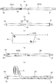
並継竿Aにおける竿先側竿体1等は次のように製作される。図5(a)に示すように、軸線に沿って束ねたガラス強化繊維の束(500本〜1000本)を熱硬化性樹脂液内に潜らせてその樹脂を含浸させた後ダイスより引き抜き所定長さに裁断して中実棒状の竿素材を形成する。ここで、強化繊維としては炭素繊維等も使用できるが、炭素繊維等に比して引張弾性率が低く柔軟性の高いガラス繊維を採用する。 使用するガラス繊維の引張弾性率としては、5Ton/mm2〜15Ton/mm2が使用できる。
The pole tip
図5(a)に示すように、中実棒状体に仕上がった竿先側竿体1を、(c)に示すセンタレス研磨機Cにより、図5(b)に示すように、竿先側部分1Aを竿元側程大径化する順テーパ面に形成し、竿先側部分1Aの竿元側に竿元側部分1Bを配し、竿元側部分1Bを竿元端側程小径化する逆テーパ面に形成してある。
図5(d)に示すように、竿先側部分1Aの後端部より竿元側部分1Bの全域に亘って、炭素繊維製の竿元端側プリプレグシート9を巻回する。竿元端側プリプレグシート9は、竿先側程広い台形状に裁断されており、厚みは2〜3mm/1000であり、3プライ巻回される。巻回された状態では、竿元端側プリプレグシート9の強化繊維cの方向は、竿軸線Xに対して傾斜する方向に引き揃えられて、螺旋状を呈している。
図5(e)に示すように、竿元端側プリプレグシート9を3プライ巻回された竿先側竿体1に対して、焼成処理によって、樹脂と強化繊維cが一体化して硬くなった竿先側竿体1の竿元側外周面に、(c)に示すセンタレス研磨機Cにより表面研磨して所望の表面精度と傾斜を確保して、竿先側竿体1の竿元端側合わせ部1Cを形成する。強化繊維cと竿軸線Xとの成す挟み角Θは45°≦Θ<90°の範囲である。望ましくは50°<Θ<70°の範囲である。
As shown in FIG. 5 (a), the rod-end
As shown in FIG. 5 (d), the rod end
As shown in FIG. 5 (e), the resin and the reinforcing fiber c were integrated and hardened by the baking treatment on the rod tip
次に、竿元側竿体2の製造工程について、マンドレル3の構造から説明する。図2(a)(b)に示すように、マンドレル3は、竿先側マンドレル部3Aと竿元側マンドレル部3Bとで構成される。マンドレル3は、通常、鋼鉄、ステンレス、チタン等の鋼材で略円錐台状に形成され、クロムメッキ等で表面塗装を施されて形成されている。
Next, a manufacturing process of the rod base
竿先側マンドレル部3Aは、先側端から元側端に掛けて、パイプ状を呈しており、外径が徐々に小さくなる逆テーパ面を有する略円錐台状に形成されている。竿元側マンドレル部3Bは、先側端から元側端に掛けて、円柱状を呈しており、外径が徐々に大きくなる正テーパ面を有する略円錐台状に形成してある。
竿元側マンドレル部3Bの先側端には、インロー芯部3bが形成してあり、竿先側マンドレル部3Aのパイプ状の内部空間を利用した元側の係合用孔3a内に係入可能に形成してある。
The pole tip
A
以上のようになる竿先側マンドレル部3Aと竿元側マンドレル部3Bとは、インロー芯部3bが元側に形成された係合用孔3a内に挿入係合され、インロー芯部3bの元側に形成された段差部3dが竿先側マンドレル部3Aの元側開口端3cに当接した状態で挿入係合が完了し、マンドレル3を一体連結形成する。その状態が図2(b)で示されている。
なお、竿先側マンドレル部3Aの竿先端部、及び、竿元側マンドレル部3Bの竿元端部には、工具係止用の孔3e、3fが形成してある。
この工具係止用の孔3e、3fに引っ掛け係止具を取付け、引き抜きシリンダ等を使用して、竿先側マンドレル部3Aと竿元側マンドレル部3Bとを分離するように構成してある。
The rod tip
A hook locking tool is attached to the
竿元側竿体2は、図4に示すように、最内層2Aと、その外側に内側テープ層2Bと、内側テープ層2Bの外側に中間シート層2Cと、その外側に外側テープ層2Dが形成されて、構成される。外側テープ層2Dの外側には竿先側と竿元側とに補強層2Eが設けられる。
As shown in FIG. 4, the rod-
最内層2Aは、竿先側端から一定範囲の長さだけ設けられ、内側に竿元側程縮径する逆テーパ面2aと逆テーパ面2aの元側から更に元側程拡径する正テーパ面2bとからなる内周面を有している。
最内層2Aは、逆テーパ状内周面側と前記正テーパ状内周面側に亘る一定範囲において、ガラス強化繊維製のプリプレグシート4を巻回している。
The
The
図2(c)に示すように、プリプレグシート4はガラス製強化繊維dを竿軸線Xに対して傾斜する方向に引き揃え、エポキシ樹脂やPET樹脂を含浸させて、シートに裁断されたプリプレグである。
ガラス強化繊維製のプリプレグシート4の竿先側端辺4aは竿軸線Xに対して直交する方向に切断され、竿元側端辺4bは竿軸線Xに対して直交する方向から傾斜する状態に切断してある。残りの2辺は、竿軸線Xに対して平行な辺を形成している。
このように、ガラス強化繊維製のプリプレグシート4によって、竿元側竿体2の竿先端側合わせ部2Fに形成してある。強化繊維dと竿軸線Xとの成す挟み角Θは45°≦Θ<90°の範囲である。望ましくは50°<Θ<70°の範囲である。したがって、前記した竿先側竿体1の竿元端側合わせ部1Cの表面強化繊維の竿軸線Xに対する傾斜角度と傾斜方向とを一致させている。
As shown in FIG. 2C, the
The rod-side end 4a of the
As described above, the
プリプレグシート4の構成としては、次のようなものでもよい。
(a)ガラス製強化繊維dを竿軸線Xに対して傾斜する方向に引き揃えたシートと竿軸線Xを挟んで反対側に傾斜する方向に引き揃えたシートとを重ね合わせたバイアス式のものでもよい。
(b)ガラス強化繊維製のプリプレグシート4は、ガラス製強化繊維dを竿軸線Xに対して傾斜する状態でかつその繊維を交差する状態に編み込んだクロス繊維に、エポキシ樹脂やPET樹脂を含浸させて、シートに裁断されたものでもよい。
(c)ガラス製強化繊維dをカーボン製強化繊維cに変更して、上記シートを構成してもよい。
以上のように裁断されたガラス強化繊維製プリプレグシート4の竿先側端辺4aを、図2(d)に示すように、マンドレル3の竿先側マンドレル部3Aの先側端に合わせた状態で巻回する。ガラス強化繊維製プリプレグシート4は、竿先側マンドレル部3Aの逆テーパ状外周面と竿元側マンドレル部3Bの正テーパ状内周面との接続点を基準点として、逆テーパ状外周面側と正テーパ状外周面側に亘る一定範囲において巻回されている。
The configuration of the
(A) A bias type in which a sheet in which glass reinforcing fibers d are aligned in the direction inclined with respect to the rod axis X and a sheet in which the glass reinforcing fibers d are aligned in the direction inclined in the opposite direction with respect to the rod axis X are overlapped. May be.
(B) The
(C) The sheet may be configured by changing the glass reinforcing fibers d to carbon reinforcing fibers c.
As shown in FIG. 2D, a state in which the rod-side end side 4a of the glass reinforced
次に、内側テープ層2Bについて説明する。図2(e)に示すように、内側テープ層2Bで使用されるものは、細幅の内側プリプレグテープ5であり、カーボン製強化繊維が複数本平行にテープ長手方向に沿って配列されており、それにエポキシ樹脂等を含浸させてプリプレグテープとしている。
この内側プリプレグテープ5を、マンドレル3に巻き付けられた最内層2Aの上から、かつ、竿元側から順次螺旋状に巻回して、内側テープ層2Bを形成する。
Next, the
The
次に、中間シート層2Cを形成する。図3(f)に示すように、中間シート層2Cを形成するのは、略細長い台形状の中間プリプレグシート6である。中間プリプレグシート6は、カーボン製強化繊維cを竿周方向及び竿軸線方向に平行に引き揃え交差配置したものにエポキシ樹脂等を含浸させてシート状に裁断されたものである。
上記したプリプレグシート6は、竿先側端辺6Aと竿元側端辺6Bとが竿軸線Xに対して直交する状態に裁断されており、内側テープ層2Bの上に最初に巻き付けられる巻始め端辺6Cは略竿軸線Xに平行に裁断され、巻終わり端辺6Dは、竿元側程竿軸線Xから離れる直線に裁断されている。そして、竿先側端辺6Aと、その竿先側端辺6Aに直交する巻始め端辺6Cとの交差位置に、竿先側端辺6Aと巻始め端辺6Cとのいずれにも斜交する切り取り面6aが形成されて、竿先側端辺6Aに向かうに連れて切り取り面6aが竿軸線Xから離れる状態に形成してある。
Next, the
The above-mentioned
中間シート層2Cの竿先側の形状において切り取り面6aによる切り欠き部分を設けているのは、最内層2Aを逆テーパ状内周面側と正テーパ状内周面側に亘る一定範囲において設けていることと密接に関係しており、中間シート層2Cを内側テープ層2Bの上に巻回した場合に、図3(g)に示すように、外周面のテーパ形状を元側程拡径する状態とするためである。
プリプレグシート6の構成としては、次のようなものでもよい。
(a)強化繊維cを竿周方向に引き揃えたシートと竿軸線方向に引き揃えたシートとを重ね合わせたバイアス式のものでもよい。
(b)強化繊維cを竿周方向に引き揃えたシートだけで構成してもよい。
(c)強化繊維cを竿軸線方向に引き揃えたシートだけで構成してもよい。
(d)竿周方向に対して傾斜する状態の強化繊維cと、竿軸線方向に対して傾斜する
状態の強化繊維cとを互いに交差する状態に編み込んだシートで構成してもよい。
The notch formed by the
The configuration of the
(A) A bias type in which a sheet in which reinforcing fibers c are aligned in the rod circumferential direction and a sheet in which the reinforcing fibers c are aligned in the rod axis direction may be overlapped.
(B) It may be constituted only by a sheet in which the reinforcing fibers c are aligned in the rod circumferential direction.
(C) The reinforcing fiber c may be constituted only by a sheet in which the reinforcing fibers c are aligned in the rod axis direction.
(D) The reinforcing fiber c in a state inclined with respect to the rod circumferential direction and the reinforcing fiber c in a state inclined with respect to the rod axis direction may be formed by a sheet in which the reinforcing fibers c are interwoven with each other.
次に、外側テープ層2Dについて説明する。図3(h)に示すように、外側テープ層2Dで使用されるものは、細幅の外側プリプレグテープ7であり、カーボン製強化繊維cが複数本平行にテープ長手方向に沿って配列されており、それにエポキシ樹脂等を含浸させてプリプレグテープとしている。
この外側プリプレグテープ7を、マンドレル3に巻き付けられた中間シート層2Cの竿先側先端から順次螺旋状に巻回して、外側テープ層2Dを形成する。
Next, the
The
内側プリプレグテープ5と外側プリプレグテープ7とは、共に、竿軸線Xに対して傾斜する状態でかつ螺旋状を描くように巻回してあるが、その巻き付け方向は互いに反対方向であり、交差するように巻き付けられている。これによって、竿元側竿体2として強度の高い、特に捻じれに強い竿体を形成できる。
内側プリプレグテープ5と外側プリプレグテープ7の巻始め位置としては、竿先側又は竿元側のいずれでも選択でき、任意である。要は、互いに内側プリプレグテープ5と外側プリプレグテープ7とが反対向きに巻回されていればよい。
内側プリプレグテープ5と外側プリプレグテープ7の夫々の巻回形態としては、螺旋状に巻回された隣接する細い幅(テープ幅)同士が、一部重なるように、又は、密着するように、或いは、少し隙間を開ける状態のものでもよい。
The
The winding start position of the
As a winding form of each of the
外側プリプレグテープ7を巻回した後には、図2(h)に示すように、竿先端と竿元端とに軸芯長の短い補強プリプレグ8を巻回する。補強プリプレグ8は、強化繊維cを交差させる状態で編み込んだクロス繊維製のものである。竿先端と竿元端に配置された補強プリプレグ8で補強層2Eを構成する。
ただし、図示はしていないが、強化繊維cを一方向に引き揃えたプリプレグを二枚揃え、互いに強化繊維cが交差するように重ねるバイアス式のものを使用してもよい。
After the
However, although not illustrated, a bias type in which two prepregs in which the reinforcing fibers c are aligned in one direction are aligned and the reinforcing fibers c intersect each other may be used.
補強プリプレグ8を巻回した後には、図示していないが、巻締テープを外側に巻回し、マンドレル3ごと焼成し、取り出した後、巻締テープを剥離する。
その後、工具係止用の孔3e、3fを介して連係されたシリンダ(図示せず)によって、竿先側マンドレル部3Aを竿先側に、竿元側マンドレル部3Bを竿元側に引き出して、竿体とマンドレル3とを分離する。その後、所定の塗装、所定長さにカットして竿体を構成する。
このように、逆テーパ面2aを有する竿体であっても、竿先側マンドレル部3Aを竿先側に引き抜く製造方法の採用によって、リーマ加工を必要とせず、強化繊維c、dが切断されず、樹脂面が荒らされない円滑な内周面を得ることができる。
After winding the reinforcing
Then, the rod-
As described above, even in the case of the rod body having the inverted tapered
因みに、図1に示すように、竿元側竿体2の竿先端側合わせ部2Fを構成する竿先端側プリプレグシート4の強化繊維dと、竿先側竿体1の竿元端側合わせ部1Cを構成する竿元端側プリプレグシート9の強化繊維cとは、竿軸線Xに対する傾斜角度(竿軸線Xと強化繊維とのなす挟み角)Θを同じにし、かつ、円周方向で同じ向きに螺旋を描くように構成してある。強化繊維の軸線方向におけるピッチは、竿先側竿体1の竿元端側合わせ部1Cと竿元側竿体2の竿先端側合わせ部2Fとが嵌合している状態で、雄ネジと雌ネジのように、互いに同ピッチで山と谷とが重なるように噛み合うことが望ましいが、必ずしも、そうである必要はない。
Incidentally, as shown in FIG. 1, the reinforcing fiber d of the rod tip
以上のように形成した竿元側竿体2の竿先端側合わせ部2Fと、竿先側竿体1の竿元端側合わせ部1Cとを組み合わせて、固定時の嵌合力を測定してみた。その結果を図8に示す。
(1)図8(a)に示すように、竿元側竿体2の竿先端側合わせ部2Fと、竿先側竿体1の竿元端側合わせ部1Cとを緩く組み合わせた状態で、錘Wで所定量l1=10mm程押し込んで、正規の合わせ状態に設定する。
(2)次に、図8(b)に示すように、竿先側竿体1の先端に引張測定器10を装着し、かつ、竿元側竿体2の竿先端位置に、竿元側竿体2と竿先側竿体1との円周方向での相対回転角度を測定する相対角度測定器14を装着して、測定する。
(3)竿元側竿体2の竿先端側合わせ部2Fと、竿先側竿体1の竿元端側合わせ部1Cとを、強く嵌合する強嵌合状態(固定状態)と緩く嵌合する緩嵌合状態(非固定状態)と、両者の中間状態とを基準状態とする。基準状態から一方方向に約30°(つまり+30°)回転させると緩嵌合状態を設定でき、基準状態から反対方向に約30°(つまりー30°)回転させると強嵌合状態(非固定状態)を設定できる。
(4)そして、基準状態から+30°、ー30°回転させた状態での引っ張りに対抗する嵌合力を測定した。
(5)因みに、本発明品の構成は、竿元側竿体2の竿先端側合わせ部2Fと、竿先側竿体1の竿元端側合わせ部1Cともに、強化繊維d、cの巻回方向は同一でかつ傾斜角度(対軸線傾斜)Θ=60°である。反対に、従来品の場合は、竿元側竿体2の竿先端側合わせ部2Fと、竿先側竿体1の竿元端側合わせ部1Cともに、軸線Xに沿った方向(対軸線傾斜)Θ=0°である。
(6)以上のようにしたテストの実績を図8(c)に示す。このテスト結果によると、発明品によると、強嵌合状態では従来品の2倍以上の嵌合力(138,6N)を示しており、緩嵌合状態では従来品の6割近くの引き抜き力で竿先側竿体1を竿元側竿体2から分離できることを示している。基準状態から相対回転させて強嵌合状態に切り替える際の相対回転させるに要する相対回転トルクも従来品に比べて1,5倍近いトルクを必要とし、強嵌合状態に切り換わったことが実感できるものとなった。
The fitting force at the time of fixing was measured by combining the rod tip side
(1) As shown in FIG. 8 (a), in a state where the rod tip side
(2) Next, as shown in FIG. 8 (b), the
(3) The rod tip
(4) Then, the fitting force against pulling in a state of being rotated by + 30 ° and −30 ° from the reference state was measured.
(5) Incidentally, the configuration of the product of the present invention is such that the reinforcing fiber d and c are both wound on the rod tip side
(6) The results of the test performed as described above are shown in FIG. According to the test results, according to the invention, the fitting force (138, 6N) is more than twice that of the conventional product in the strong fitting state, and the pulling force is about 60% of the conventional product in the loose fitting state. This shows that the rod-
次に、前記した基準状態から強嵌合状態(固定状態)及び緩嵌合状態(非固定状態)に切り換え操作する際に、手助けとなる指標について説明する。
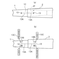
図11に示すように、竿先側竿体1の竿元端側合わせ部1Cと、竿元側竿体2の竿先端側合わせ部2Fの夫々の外周面に、竿元端側合わせ部1Cと竿先端側合わせ部2Fとが特定の相対位置関係に設定されたことを示す指標13が設けられている。
Next, a description will be given of indices that assist in switching from the above-described reference state to a strong fitting state (fixed state) and a loosely fitting state (non-fixed state).
As shown in FIG. 11, a rod-end end
指標13としては、図11(a)に示すように、黒丸を採用する。又は、黒丸13より細線13Aを互いに相手側に向けて延出し、互いの細線13Aが竿元側竿体2の竿先端において一致するような構成を採ってもよい。
As the
この指標13によって特定の相対位置関係に設定されたことを示す場合としては、下記のようなものがある。
(a)指標13が強嵌合状態(固定状態)を示す。
(b)指標13が緩嵌合状態(非固定状態)を示す。
(c)指標13が基準状態を示す。
上記指標13としては、黒丸を採用しているが、各種の記号図形等を記載できる。
The following is a case where the
(A) The
(B) The
(C) The
Although a black circle is used as the
上記場合については、黒丸13での簡素な構成のものを示したが、図11(b)に示すように、回転操作方向を示す矢印13Bや説明文13Cを追加してもよい。
これによって、より操作が容易になると思われる。説明文としては、固定状態を示すLOCK(カッコ付き)及び非固定状態を示すRELEASE(カッコ付き)を付与する。
ここでは、丸13が基準状態を示し、LOCK方向に相対回転させて捩じり操作すると固定状態を現出できる。反対にRELEASE方向に相対回転させて捩じり操作すると非固定状態を現出できる。
In the above case, the simple configuration with the
This would make operation easier. LOCK (with parentheses) indicating a fixed state and RELEASE (with parentheses) indicating a non-fixed state are given as explanatory texts.
Here, a
〔第1実施形態の別実施形態〕
竿先側竿体1としては、中実棒状体ではなく、円筒状のもので構成してもよい。
つまり、炭素繊維製の強化繊維c(又はガラス製の強化繊維d)を一方向に引き揃え、その引き揃え強化繊維群にエポキシ樹脂等の熱硬化性樹脂(又は熱可塑性樹脂)を含浸させて、プリプレグシートを形成する。
図9(a)に示すように、このプリプレグシート10A、10Bを略台形状に裁断した複数のものをマンドレル3に巻回する。ここでは、強化繊維c、dを円周方向に引き揃えたプリプレグシート10Aと強化繊維c、dを軸線方向に引き揃えたプリプレグシート10Bとをマンドレル3に巻回する。
[Another Embodiment of the First Embodiment]
The rod tip
That is, the reinforcing fibers c made of carbon fibers (or the reinforcing fibers d made of glass) are aligned in one direction, and the aligned reinforcing fiber group is impregnated with a thermosetting resin (or a thermoplastic resin) such as an epoxy resin. To form a prepreg sheet.
As shown in FIG. 9A, a plurality of
次に、中実棒状体と同様に、竿元側竿体2の竿先端側合わせ部2Fに嵌合すべく、竿先側竿体1の竿元端側合わせ部1Cを形成する研削加工を行う。図5(c)に示すセンタレス研磨機Cにより、図9(c)に示すように、竿元側程大径化する順テーパ面に形成してある竿先側部分1Aの竿元側に竿元側部分1Bを配し、竿元側部分1Bを竿元端側程小径化する逆テーパ面に形成してある。
Next, similarly to the solid rod-shaped body, a grinding process for forming the rod base end side
図9(c)(d)に示すように、竿先側部分1Aの後端部より竿元側部分1Bの全域に亘って、炭素繊維製の竿元端側プリプレグシート9を巻回する。竿元端側プリプレグシート9は、竿先側程広い台形状に裁断されており、厚みは2〜3mm/1000であり、3プライ巻回される。巻回された状態では、竿元端側プリプレグシート9の強化繊維cの方向は、竿軸線Xに対して傾斜する方向に引き揃えられて、螺旋状を呈している。
As shown in FIGS. 9 (c) and 9 (d), the rod end
図9(d)に示すように、竿元端側プリプレグシート9を3プライ巻回された竿先側竿体1に対して、焼成処理によって、樹脂と強化繊維cが一体化して硬くなった竿先側竿体1の竿元側外周面に、5(c)に示すセンタレス研磨機Cにより表面研磨して所望の表面精度と傾斜を確保して、竿先側竿体1の竿元端側合わせ部1Cを形成する。図9(e)に示すように、強化繊維cと竿軸線Xとの成す挟み角Θは45°≦Θ<90°の範囲である。望ましくは50°<Θ<70°の範囲である。
As shown in FIG. 9 (d), the resin and the reinforcing fiber c were integrated and hardened by the baking treatment on the rod tip
プリプレグを構成する強化繊維としては、具体的には、炭素繊維以外にガラス繊維、アラミド繊維、アルミナ繊維等が使用でき、樹脂としては、エポキシ樹脂の他に、フェノール樹脂、ポリエステル樹脂等の熱硬化性樹脂やPV(E)等の熱可塑性樹脂が使用できる 。また、プリプレグとしては、強化繊維を編み込んだ織り物に樹脂を含浸させて構成したものであってもよい。 As the reinforcing fiber constituting the prepreg, specifically, besides carbon fiber, glass fiber, aramid fiber, alumina fiber and the like can be used. In addition to epoxy resin, thermosetting resin such as phenol resin and polyester resin can be used. A thermoplastic resin such as a conductive resin or PV (E) can be used. Further, as the prepreg, a woven fabric in which reinforcing fibers are woven may be impregnated with a resin.
次に、竿元側竿体2の別実施構造を説明する。上記した第1実施形態においては、連結分離可能な二つのマンドレル3A、3Bを使用して竿元側竿体2を形成したが、ここでは単一のマンドレル3によって、竿元側竿体2を作成する。
図10(a)に示すように、竿元側竿体2の竿先端側合わせ部2Fを形成する為に、炭素繊維製の竿先端側プリプレグシート11を巻回する。竿先端側プリプレグシート11は、竿元側程広い台形状に裁断されており、厚みは2〜3mm/1000であり、3プライ巻回される。巻回された状態では、竿先端側プリプレグシート11の強化繊維cの方向は、竿軸線Xに対して傾斜する方向に引き揃えられて、螺旋状を呈している。
Next, another embodiment structure of the rod base
As shown in FIG. 10A, a rod tip
竿先端側プリプレグシート11を巻回された竿素材に対して図10(b)に示すように、3枚のプリプレグシート12A、12B、12Cを巻回する。これら3枚のプリプレグシートは、内側から強化繊維cが円周方向に引き揃えられた内側プリプレグシート12Aと、強化繊維cが軸線方向に引き揃えられた中間側プリプレグシート12Bと、強化繊維cが円周方向に引き揃えられた外側プリプレグシート12Cの3枚である。
As shown in FIG. 10B, three
図10(c)に示すように、3枚のプリプレグシート12A、12B、12Cを巻回された竿素材に対してマンドレル3とともに、焼成処理を行い、マンドレル3を脱芯する。焼成後、樹脂と強化繊維cが一体化して硬くなった竿元側竿体2の竿先側内周面に、図10(d)(e)に示すように、リーマRにより内面研磨して所望の表面精度と傾斜を確保して、竿元側竿体2の竿先端側合わせ部2Fを形成する。図10(f)に示すように、強化繊維cと竿軸線Xとの成す挟み角Θは45°≦Θ<90°の範囲である。望ましくは50°<Θ<70°の範囲である。
竿先端側プリプレグシート11の代わりに、厚めのプリプレグテープを巻回してもよい。
As shown in FIG. 10C, the rod material on which the three
Instead of the
〔第2実施形態〕
ここでは、図示はしていないが、第1実施形態で示した、竿先側竿体1の竿元側外周面と竿元側竿体2の竿先側内周面との一方に、前記した軸芯長の短い炭素繊維製プリプレグシートを巻回し、竿先側竿体1の竿元側外周面と竿元側竿体2の竿先側内周面との他方に、不織布を配置して、竿先側竿体1の竿元端側合わせ部1Cと竿元側竿体2の竿先端側合わせ部2Fを構成してもよい。
[Second embodiment]
Here, although not shown, one of the rod-side outer peripheral surface of the rod-
不織布は、強化繊維cを引き揃えたものに樹脂を含侵させてシート状にしたものではなく、繊維を熱・機械的又は化学的な作用によって接着又は絡み合わせることで布にしたものであり、繊維の向きはランダムである。
プリプレグシートについては、図10(b)に示すように、竿先側竿体1の竿元端側合わせ部1Cと竿元側竿体2の竿先端側合わせ部2Fとの何れか一方に施す際に、前記した厚み、縦横の広さ等を有し、3プライ分巻回される。
The nonwoven fabric is not made into a sheet by impregnating a resin with a set of reinforcing fibers c, but into a fabric by bonding or entanglement of the fibers by a thermo-mechanical or chemical action. The orientation of the fibers is random.
As shown in FIG. 10 (b), the prepreg sheet is applied to one of the rod-end-
このような構成によって、竿先側竿体1と竿元側竿体2とを一方方向に相対回転させると、竿先側竿体1が竿元側竿体2内に更に入り込む状態になり、合わせ部1C、2Fがきつく締まってスッポ抜け現象等が抑制される。他方、前記とは反対方向に夫々相対回転させると、竿先側竿体1が竿元側竿体2から離れる方向に移動し、両者の固着状態が緩和され、竿先側竿体1が竿元側竿体2から分離されて、仕舞処理が容易におこなえる。
With such a configuration, when the rod-tip-
〔第3実施形態〕
ここでは、振出竿Bに対して本発明を適用した状態を示す。竿先側竿体から竿元側竿体を5〜6本備えた振出竿Bにおいて、図6に示すように、竿先側竿体1を竿元側竿体2より引き出して釣り状態に設定する場合に、竿先側竿体1の竿元端側合わせ部1Cと竿元側竿体2の竿先端側合わせ部2Fとが嵌合する状態にある。この場合に、竿先側竿体1の竿元端側合わせ部1Cの表面に表出した強化繊維c、dの竿軸線Xに対する傾斜方向と向きは、竿元側竿体2の竿先端側合わせ部2Fの表面に表出した強化繊維c、dの竿軸線Xに対する傾斜方向と向きと同一である。
また、図示してはいないが、強化繊維c、dと竿軸線Xとの成す挟み角Θは45°≦Θ<90°の範囲である。望ましくは50°<Θ<70°の範囲である。
[Third embodiment]
Here, a state in which the present invention is applied to the swing rod B is shown. In the drawing rod B provided with 5 to 6 rod-side rods from the rod-side rod, the rod-
Although not shown, the included angle Θ between the reinforcing fibers c and d and the rod axis X is in the range of 45 ° ≦ Θ <90 °. Preferably, it is in the range of 50 ° <Θ <70 °.
このような構成によって、竿先側竿体1と竿元側竿体2とを一方方向に相対回転させると、竿先側竿体1が竿元側竿体2より更に突出する状態になり、合わせ部1C、2Fがきつく締まってスッポヌケ現象等が抑制される。他方、前記とは反対方向に夫々相対回転させると、竿先側竿体1が竿元側竿体2内に入り込んで、両者の固着状態が緩和され、竿先側竿体1が竿元側竿体2内に入り込んで、仕舞処理が容易におこなえる。
With such a configuration, when the rod-tip-
〔第4実施形態〕
ここでは、図7に示すように、インロー継竿Cに対して本発明を適用した状態を示す。竿先側竿体1から竿元側竿体に向けてインロー芯材1cを延出するとともに、竿元側竿体2として、第1実施形態で示した竿体を使用する。図5(d)に示すように、インロー芯材1cの外周面を竿元側程小径の逆テーパ面に形成するとともに、その傾斜面に炭素繊維製の竿元端側プリプレグシート9を巻回する。竿元端側プリプレグシート9は、竿先側程広い台形状に裁断されており、厚みは2〜3mm/1000であり、3プライ巻回される。巻回された状態では、竿元端側プリプレグシート9の強化繊維cの方向は、竿軸線Xに対して傾斜する方向に引き揃えられて、螺旋状を呈している。
[Fourth embodiment]
Here, as shown in FIG. 7, a state in which the present invention is applied to the spigot joint C is shown. The rod body shown in the first embodiment is used as the rod-
前記したと同様に、竿元端側プリプレグシート9を3プライ巻回されたインロー芯材1cに対して、焼成処理によって、樹脂と強化繊維cが一体化して硬くなった外周面に、図5(c)に示すセンタレス研磨機により表面研磨して所望の表面精度と傾斜を確保して、インロー芯材1cを形成し、図7に示すように、そのインロー芯材1cを竿先側竿体1の竿元側端部より突出させて、合わせ部1Cを形成する。強化繊維cと竿軸線Xとの成す挟み角Θは45°≦Θ<90°の範囲である。望ましくは50°<Θ<70°の範囲である。
In the same manner as described above, the
このような構成によって、竿先側竿体1と竿元側竿体2とを一方方向に相対回転させると、竿先側竿体1のインロー芯材1cが更に竿元側竿体2内に入り込み、合わせ部1C、2Fがきつく締まってスッポヌケ現象等が抑制される。他方、前記とは反対方向に夫々相対回転させると、竿先側竿体1が竿元側竿体2から離間する状態になり、両者の固着状態が緩和され、両者を分離する仕舞処理が容易におこなえる。
With such a configuration, when the pole tip
〔別実施形態〕
逆並継竿に適用してもよい。図1(a)において、竿先側竿体1と竿元側竿体2とを入れ替えて構成して、逆並継竿を構成する。つまり、竿元側竿体2の竿先端部を竿先側程小径化するテーパ外周面に形成し、かつ、竿先側竿体1の竿元端部に、竿元側程大径化するテーパ内周面を形成して構成することができる。
[Another embodiment]
You may apply to a reverse parallel joint rod. In FIG. 1 (a), the pole tip
本願発明は、釣り操作時には仕掛けを投入する際にも竿先側竿体が竿元側竿体より分離することを抑制できるとともに、釣りを終えて仕舞い処理する際には確実に竿先側竿体と竿元側竿体とを分離できる釣り竿の合わせ部構造を提供するものである。 The invention of the present application can prevent the rod tip side rod body from being separated from the rod base side rod body even when throwing in a gimmick at the time of fishing operation, and when the fishing is finished and the end processing is performed, the rod tip side rod is surely secured. It is an object of the present invention to provide a fitting structure of a fishing rod capable of separating a body and a rod base side rod body.
1 竿先側竿体
1A 竿先側部分
1B 竿元側部分
1a 逆テーパ面
1C 竿元端側合わせ部
2 竿元側竿体
2A 最内層
2B 内側テープ層
2C 中間シート層
2D 外側テープ層
2E 補強層
2F 竿先端側合わせ部
2a 逆テーパ面
2b 正テーパ面
3 マンドレル
3A 竿先側マンドレル部
3B 竿元側マンドレル部
3a 係合用孔
3b インロー芯部
3c 元側開口端
3d 段差部
4 ガラス強化繊維製プリプレグシート
4a 竿先側端辺
5 内側プリプレグテープ
6 中間プリプレグシート
6A 竿先側端辺
6B 竿元側端辺
6C 巻始め端辺
6D 巻終り端辺
6a 切り取り面
7 外側プリプレグテープ
8 補強プリプレグ
9 竿元端側プリプレグシート
10 引張測定器
11 竿先端側プリプレグシート
12A、12B、12C プリプレグシート
13 指標
13A 細線
13B 矢印
13C 説明文
14 相対角度計
A 並継竿
Θ 強化繊維と竿軸線との成す挟み角
R リーマ
X 竿軸線
W 錘
c カーボン製強化繊維
d ガラス製強化繊維
DESCRIPTION OF
Claims (6)
(a)前記小径穂先側竿体の前記竿元端側合わせ部を、前記大径穂持竿体の前記竿先端側合わせ部内に嵌合して固定状態を作り出す並継式の竿体
(b)前記大径穂持竿体の前記竿先端側合わせ部を、前記小径穂先側竿体の前記竿元端側合わせ部内に嵌合して固定状態を作り出す逆並継式の竿体
(c)前記竿先端側合わせ部、又は、前記竿元端側合わせ部が傾斜外周面を形成したインロー芯材であり、インロー芯材を相手側合わせ部に嵌合して固定状態を作り出すインロー継式の竿体
の内のいずれか一つを形成してある請求項1又は2記載の釣竿の合わせ部構造。 The rod tip side rod body is a solid rod-shaped or hollow cylindrical small diameter tip side rod body located on the rod tip side, and the rod origin side rod body is a hollow cylindrical large diameter ear tip located on the rod origin side. A rod,
(A) A joint type rod body in which the rod base end side mating portion of the small diameter ear tip side rod body is fitted into the rod tip side mating portion of the large diameter ear holding rod body to create a fixed state. And (c) a reverse-joint type rod body that fits the rod tip side mating portion of the large-diameter ear tip rod body into the rod base end side mating portion of the small-diameter ear tip rod body to create a fixed state. The rod tip side mating portion, or the rod base end side mating portion is a spigot core material having an inclined outer peripheral surface, and a spigot splicing type that creates a fixed state by fitting the spigot core material to the mating side mating portion. 3. The fitting structure of a fishing rod according to claim 1, wherein one of the rods is formed.
(a)前記小径穂先側竿体の前記竿元端側合わせ部を、前記大径穂持竿体の前記竿先端側合わせ部内に嵌合して固定状態を作り出す並継式の竿体
(b)前記大径穂持竿体の前記竿先端側合わせ部を、前記小径穂先側竿体の前記竿元端側合わせ部内に嵌合して固定状態を作り出す逆並継式の竿体
(c)前記竿先端側合わせ部、又は、前記竿元端側合わせ部が傾斜外周面を形成したインロー芯材であり、インロー芯材を相手側合わせ部に嵌合して固定状態を作り出すインロー継式の竿体
の内のいずれか一つを形成してある請求項3記載の釣竿の合わせ部構造。 An inclined outer circumferential surface is formed on one of the rod end end mating portion and the rod tip side mating portion, and an inclined inner peripheral surface is formed on the other of the rod end end mating portion and the rod tip side mating portion. hand,
(A) A joint type rod body in which the rod base end side mating portion of the small diameter ear tip side rod body is fitted into the rod tip side mating portion of the large diameter ear holding rod body to create a fixed state. And (c) a reverse-joint type rod body that fits the rod tip side mating portion of the large-diameter ear tip rod body into the rod base end side mating portion of the small-diameter ear tip rod body to create a fixed state. The rod tip side mating portion, or the rod base end side mating portion is a spigot core material having an inclined outer peripheral surface, and a spigot splicing type that creates a fixed state by fitting the spigot core material to the mating side mating portion. 4. The fitting structure for a fishing rod according to claim 3, wherein any one of the rods is formed.
Priority Applications (3)
| Application Number | Priority Date | Filing Date | Title |
|---|---|---|---|
| JP2018130082A JP7165520B2 (en) | 2018-07-09 | 2018-07-09 | Joint structure of fishing rod |
| CN201910612027.9A CN110692607B (en) | 2018-07-09 | 2019-07-08 | Joint structure of fishing rod |
| KR1020190082138A KR102790745B1 (en) | 2018-07-09 | 2019-07-08 | Joint structure for fishing rod |
Applications Claiming Priority (1)
| Application Number | Priority Date | Filing Date | Title |
|---|---|---|---|
| JP2018130082A JP7165520B2 (en) | 2018-07-09 | 2018-07-09 | Joint structure of fishing rod |
Publications (2)
| Publication Number | Publication Date |
|---|---|
| JP2020005573A true JP2020005573A (en) | 2020-01-16 |
| JP7165520B2 JP7165520B2 (en) | 2022-11-04 |
Family
ID=69149669
Family Applications (1)
| Application Number | Title | Priority Date | Filing Date |
|---|---|---|---|
| JP2018130082A Active JP7165520B2 (en) | 2018-07-09 | 2018-07-09 | Joint structure of fishing rod |
Country Status (3)
| Country | Link |
|---|---|
| JP (1) | JP7165520B2 (en) |
| KR (1) | KR102790745B1 (en) |
| CN (1) | CN110692607B (en) |
Cited By (1)
| Publication number | Priority date | Publication date | Assignee | Title |
|---|---|---|---|---|
| JP7668705B2 (en) | 2021-08-24 | 2025-04-25 | 株式会社シマノ | Fishing rod with a fishing tip and a fishing rod equipped with the same |
Citations (5)
| Publication number | Priority date | Publication date | Assignee | Title |
|---|---|---|---|---|
| JP2001178314A (en) * | 1999-12-24 | 2001-07-03 | Ryobi Ltd | Fishing rod |
| JP2002101790A (en) * | 2000-09-28 | 2002-04-09 | Shimano Inc | Fitting structure of rod body |
| JP2002112670A (en) * | 2000-10-11 | 2002-04-16 | Shimano Inc | Fishing rod |
| JP2002209478A (en) * | 2001-01-17 | 2002-07-30 | Shimano Inc | Fishing rod connection structure |
| JP2014064520A (en) * | 2012-09-26 | 2014-04-17 | Shimano Inc | Solid rod |
Family Cites Families (6)
| Publication number | Priority date | Publication date | Assignee | Title |
|---|---|---|---|---|
| JP2003070390A (en) * | 2001-08-31 | 2003-03-11 | Daiwa Seiko Inc | Head rod or single rod |
| JP3880385B2 (en) | 2001-12-07 | 2007-02-14 | ダイワ精工株式会社 | fishing rod |
| US20040200123A1 (en) | 2003-02-27 | 2004-10-14 | Kenneth Whiting | Two piece bonded fishing rod blank and fishing rod |
| JP4784968B2 (en) * | 2005-03-11 | 2011-10-05 | 株式会社シマノ | Fishing rod |
| JP5376594B2 (en) | 2009-11-30 | 2013-12-25 | グローブライド株式会社 | Fishing rod with inlay joint structure |
| JP6344905B2 (en) | 2013-11-28 | 2018-06-20 | 株式会社シマノ | fishing rod |
-
2018
- 2018-07-09 JP JP2018130082A patent/JP7165520B2/en active Active
-
2019
- 2019-07-08 CN CN201910612027.9A patent/CN110692607B/en active Active
- 2019-07-08 KR KR1020190082138A patent/KR102790745B1/en active Active
Patent Citations (5)
| Publication number | Priority date | Publication date | Assignee | Title |
|---|---|---|---|---|
| JP2001178314A (en) * | 1999-12-24 | 2001-07-03 | Ryobi Ltd | Fishing rod |
| JP2002101790A (en) * | 2000-09-28 | 2002-04-09 | Shimano Inc | Fitting structure of rod body |
| JP2002112670A (en) * | 2000-10-11 | 2002-04-16 | Shimano Inc | Fishing rod |
| JP2002209478A (en) * | 2001-01-17 | 2002-07-30 | Shimano Inc | Fishing rod connection structure |
| JP2014064520A (en) * | 2012-09-26 | 2014-04-17 | Shimano Inc | Solid rod |
Cited By (1)
| Publication number | Priority date | Publication date | Assignee | Title |
|---|---|---|---|---|
| JP7668705B2 (en) | 2021-08-24 | 2025-04-25 | 株式会社シマノ | Fishing rod with a fishing tip and a fishing rod equipped with the same |
Also Published As
| Publication number | Publication date |
|---|---|
| JP7165520B2 (en) | 2022-11-04 |
| CN110692607B (en) | 2022-11-04 |
| KR20200006011A (en) | 2020-01-17 |
| CN110692607A (en) | 2020-01-17 |
| KR102790745B1 (en) | 2025-04-07 |
Similar Documents
| Publication | Publication Date | Title |
|---|---|---|
| JP6757581B2 (en) | Fiber reinforced plastic | |
| JP4784968B2 (en) | Fishing rod | |
| WO2003092372A1 (en) | Fishing rod | |
| JP7165520B2 (en) | Joint structure of fishing rod | |
| JP6789902B2 (en) | Manufacturing method of fiber reinforced plastic | |
| KR20200034610A (en) | Fishiing rod and rod body | |
| JP4623565B2 (en) | Enclosure for drawer | |
| JP5171607B2 (en) | Manufacturing method of fishing spool | |
| JP5608577B2 (en) | fishing rod | |
| KR960014835B1 (en) | Method of manufacturing tubular elements forming a telescopic or detachable fishing rod | |
| JPS63166519A (en) | Rod-shaped object made of fiber reinforced resin | |
| JP4311534B2 (en) | Earhead | |
| JP2000236781A (en) | Rod body for fishing rod, internally threadable fishing rod and its production | |
| JP6095309B2 (en) | Side by side | |
| JP2002101790A (en) | Fitting structure of rod body | |
| JP4641888B2 (en) | Earhead | |
| JPWO2013146837A1 (en) | Method for manufacturing tubular body | |
| JP5376594B2 (en) | Fishing rod with inlay joint structure | |
| JP6800803B2 (en) | Improvement of the joint structure of the rod body | |
| JP3553365B2 (en) | fishing rod | |
| JP2001299157A (en) | Fitting structure of rod boy | |
| JP2002233274A (en) | Spinning rod | |
| JP2001314139A (en) | Fishing rod body | |
| JP4315324B2 (en) | Threading casket and method for manufacturing piercing casket | |
| JP2001238574A (en) | Fishing rod |
Legal Events
| Date | Code | Title | Description |
|---|---|---|---|
| A521 | Request for written amendment filed |
Free format text: JAPANESE INTERMEDIATE CODE: A523 Effective date: 20180724 |
|
| RD01 | Notification of change of attorney |
Free format text: JAPANESE INTERMEDIATE CODE: A7421 Effective date: 20190610 |
|
| A621 | Written request for application examination |
Free format text: JAPANESE INTERMEDIATE CODE: A621 Effective date: 20210507 |
|
| A977 | Report on retrieval |
Free format text: JAPANESE INTERMEDIATE CODE: A971007 Effective date: 20220216 |
|
| A131 | Notification of reasons for refusal |
Free format text: JAPANESE INTERMEDIATE CODE: A131 Effective date: 20220222 |
|
| A521 | Request for written amendment filed |
Free format text: JAPANESE INTERMEDIATE CODE: A523 Effective date: 20220401 |
|
| A02 | Decision of refusal |
Free format text: JAPANESE INTERMEDIATE CODE: A02 Effective date: 20220705 |
|
| A521 | Request for written amendment filed |
Free format text: JAPANESE INTERMEDIATE CODE: A523 Effective date: 20220901 |
|
| C60 | Trial request (containing other claim documents, opposition documents) |
Free format text: JAPANESE INTERMEDIATE CODE: C60 Effective date: 20220901 |
|
| A911 | Transfer to examiner for re-examination before appeal (zenchi) |
Free format text: JAPANESE INTERMEDIATE CODE: A911 Effective date: 20220908 |
|
| C21 | Notice of transfer of a case for reconsideration by examiners before appeal proceedings |
Free format text: JAPANESE INTERMEDIATE CODE: C21 Effective date: 20220913 |
|
| TRDD | Decision of grant or rejection written | ||
| A01 | Written decision to grant a patent or to grant a registration (utility model) |
Free format text: JAPANESE INTERMEDIATE CODE: A01 Effective date: 20221018 |
|
| A61 | First payment of annual fees (during grant procedure) |
Free format text: JAPANESE INTERMEDIATE CODE: A61 Effective date: 20221024 |
|
| R150 | Certificate of patent or registration of utility model |
Ref document number: 7165520 Country of ref document: JP Free format text: JAPANESE INTERMEDIATE CODE: R150 |
|
| R250 | Receipt of annual fees |
Free format text: JAPANESE INTERMEDIATE CODE: R250 |