JP2020007729A - Fixing nut for screw reinforcement and method for producing the same - Google Patents
Fixing nut for screw reinforcement and method for producing the same Download PDFInfo
- Publication number
- JP2020007729A JP2020007729A JP2018127227A JP2018127227A JP2020007729A JP 2020007729 A JP2020007729 A JP 2020007729A JP 2018127227 A JP2018127227 A JP 2018127227A JP 2018127227 A JP2018127227 A JP 2018127227A JP 2020007729 A JP2020007729 A JP 2020007729A
- Authority
- JP
- Japan
- Prior art keywords
- screw
- nut
- mold
- core
- fixing nut
- Prior art date
- Legal status (The legal status is an assumption and is not a legal conclusion. Google has not performed a legal analysis and makes no representation as to the accuracy of the status listed.)
- Granted
Links
Images




Landscapes
- Reinforcement Elements For Buildings (AREA)
Abstract
【課題】鋳造法に従って製造する際のバリ除去等の労力が軽減され、その結果、低い製造コストにて製造することが可能なねじ鉄筋用定着ナットを提供すること。【解決手段】螺合軸方向の両端において開口し、内周面に雌ねじが形成された螺合孔を有するねじ鉄筋用定着ナットにおいて、螺合軸方向における一方の端から他方の端に延び、且つそれら両端にて外方に開口する二本の凹溝を、互いに対向して、雌ねじを横断するように形成した。【選択図】図1PROBLEM TO BE SOLVED: To provide a fixing nut for a screw reinforcing bar which can be manufactured at a low manufacturing cost as a result of reducing labor such as deburring during manufacturing according to a casting method. SOLUTION: In a fixing nut for a screw reinforcing bar which is open at both ends in the screwing axis direction and has a screw hole in which a female thread is formed on an inner peripheral surface, it extends from one end to the other end in the screwing axis direction. In addition, two concave grooves that open outward at both ends are formed so as to face each other and cross the female screw. [Selection diagram] Fig. 1
Description
本発明は、ねじ鉄筋をコンクリートに定着させる際に用いられるねじ鉄筋用定着ナット、及びその製造方法に関するものである。 The present invention relates to a fixing nut for a screw rebar used when fixing a screw rebar to concrete, and a method for manufacturing the same.
鉄筋コンクリート構造物において、ねじ鉄筋等の異形鉄筋をコンクリートに定着させることを目的として、定着ナットや定着金物等と称される定着具が使用される場合がある。そのような定着具は、一般に、ねじ鉄筋等の異形鉄筋の端部に装着された後、異形鉄筋との間のクリアランスに有機系又は無機系のグラウト(材)が注入され、固着せしめられることによって使用されている。 BACKGROUND ART In a reinforced concrete structure, a fixing tool called a fixing nut, a fixing metal, or the like may be used in order to fix a deformed reinforcing bar such as a screw reinforcing bar to concrete. Generally, such a fixing device is attached to an end of a deformed reinforcing bar such as a screw reinforcing bar, and then an organic or inorganic grout (material) is injected into a clearance between the deformed reinforcing bars and fixed. Used by
コンクリートにねじ鉄筋等の異形鉄筋を定着させるための定着具については、従来より、様々なものが提案され、使用されている。例えば、特許文献1(特開2003−213841号公報)においては、開口した両端を有するとともに内周に雌ねじを有し、ねじ鉄筋を螺合状態で貫通させる筒部と、この筒部から径方向、外方向に突出する環状の鍔部とを備え、上記筒部とねじ鉄筋との間のクリアランスに充填されるグラウトによりねじ鉄筋に固定され、当該ねじ鉄筋をコンクリートに定着させる定着金物として、筒部の中央に、グラウトを注入するための注入口が形成されており、また、かかる筒部の中央の内周には注入口に連なる環状溝が形成されており、グラウト注入前の状態では環状溝が筒部とねじ鉄筋のクリアランスを介して上記両端開口に連なることを特徴とする定着金物が、提案されている。 Various fixing devices for fixing deformed reinforcing bars such as screw reinforcing bars to concrete have been conventionally proposed and used. For example, in Patent Literature 1 (Japanese Patent Application Laid-Open No. 2003-213841), a tubular portion having both open ends and a female screw on the inner periphery, and threading a threaded rebar in a threaded state, and a radial portion extending from the tubular portion An annular flange portion protruding outward, fixed to the screw rebar by grout filled into the clearance between the cylindrical portion and the screw rebar, and a fixing metal for fixing the screw rebar to concrete, An injection port for injecting grout is formed in the center of the portion, and an annular groove connected to the injection port is formed in the inner periphery of the center of the cylindrical portion, and an annular groove is formed before grout injection. Fixing hardware has been proposed in which a groove is continuous with the opening at both ends through a clearance between a cylindrical portion and a screw reinforcing bar.
ところで、ねじ鉄筋等の異形鉄筋をコンクリートに定着させる際に使用される定着具は、その大きさや形状等に応じて、従来より公知の各種製造方法に従って製造されているが、特に砂型を用いた鋳造法を採用することにより、製造コストを低く抑えることが可能である等の利点を享受することが出来る。砂型を用いた鋳造法に従い、ねじ鉄筋の端部に螺着させて用いられるナット(ねじ鉄筋用定着ナット。以下、単にナットとも言う。)を製造する場合、一般には、ねじ鉄筋用定着ナットの外形を成形するための一対の上型及び下型と、螺合孔(及びその内周面の雌ねじ)を成形するための中子が用いられる。 By the way, fixing devices used when fixing deformed reinforcing bars such as screw reinforcing bars to concrete are manufactured according to conventionally known various manufacturing methods according to the size and shape thereof, and particularly, a sand mold is used. By adopting the casting method, it is possible to enjoy advantages such as a reduction in manufacturing cost. When manufacturing a nut (an anchor nut for a screw rebar; hereinafter, also simply referred to as a nut) to be screwed to an end of a screw rebar according to a casting method using a sand mold, generally, a fixing nut for a screw rebar is used. A pair of upper and lower dies for forming an outer shape and a core for forming a screw hole (and a female screw on the inner peripheral surface thereof) are used.
しかしながら、鋳造法によってねじ鉄筋用定着ナットを製造すると、以下の如き要因によって、製造コストが悪化する恐れがある。先ず、ナットの螺合孔を形成するために用いられる中子は、螺合孔内周面に精度良く雌ねじを成形することが可能なシェル中子(シェルモールド造型法に従って製造された中子)が有利に用いられるが、かかるシェル中子も、一対の成形型(上型及び下型)を用いて造型されることが一般的であり、中子表面における成形型の型合わせ面に対応する部位に微小ながらもバリが発生する場合がある。そのようなバリは、鋳造物たるナットにおける雌ねじの形状精度に影響を及ぼす恐れがあることから、ナットの鋳造を実施する前に検品等の工程が必要であり、結果として、ナットの製造コストを悪化させる恐れがある。また、中子並びに一対の上型及び下型を用いてねじ鉄筋用定着ナットを鋳造すると、得られるナット表面における上型と下型との型合わせ面に対応する部位には、不可避的にバリが発生する。そのようなバリが、ねじ鉄筋が螺入される螺合孔における螺合軸方向の両端付近に僅かでも残ると、ねじ鉄筋へのナットの螺入が妨げられる恐れがあるところから、バリの除去は細心の注意を払いながら実施する必要があり、その結果、製造コストの増大させる要因となる。更に、ねじ鉄筋用定着ナットには、ナットとねじ鉄筋との間のクリアランスにグラウト(材)を注入するための注入孔が必要とされるところ、鋳造によりナットを製造する場合には、鋳造後に注入孔を形成するための別工程を実施することが一般的であり、そのような別工程の存在が、ナットの製造コストを悪化させていた。 However, when the fixing nut for the screw reinforcing bar is manufactured by the casting method, the manufacturing cost may be deteriorated due to the following factors. First, a core used for forming a screw hole of a nut is a shell core (core manufactured according to a shell molding method) capable of accurately forming a female screw on the inner peripheral surface of the screw hole. Is advantageously used, but such a shell core is generally formed using a pair of forming dies (upper die and lower die), and corresponds to the mold mating surface of the forming die on the core surface. Burrs may be generated even though they are minute. Since such burrs may affect the shape accuracy of the female screw in the nut as a casting, a process such as inspection is required before casting the nut, and as a result, the manufacturing cost of the nut is reduced. May worsen. In addition, when a fixing nut for a screw rebar is cast using a core and a pair of upper and lower dies, a portion of the obtained nut surface corresponding to the mating surface between the upper and lower dies is inevitably flashed. Occurs. If any such burrs remain near both ends in the screwing axial direction of the screwing holes into which the screw rebars are screwed, removal of the burrs may be hindered from screwing the nut into the screw rebars. Must be carried out with great care and, as a result, increase manufacturing costs. Further, the fixing nut for a screw rebar requires an injection hole for injecting grout (material) into a clearance between the nut and the screw rebar, but when the nut is manufactured by casting, after the casting, It is common to perform another step for forming the injection hole, and the existence of such another step has exacerbated the manufacturing cost of the nut.
そのような状況の下、本発明は完成されるに至ったものであり、その解決すべき課題とするところは、鋳造法に従って製造する際のバリ除去等の労力が軽減され、その結果、低い製造コストにて製造することが可能なねじ鉄筋用定着ナットを提供することにある。また、本発明は、そのようなねじ鉄筋用定着ナットを有利に製造することが出来る方法を提供することをも、その解決課題とするものである。 Under such circumstances, the present invention has been completed, and the problem to be solved is that labor for removing burrs at the time of manufacturing according to the casting method is reduced, and as a result, An object of the present invention is to provide a fixing nut for a screw rebar that can be manufactured at a manufacturing cost. Another object of the present invention is to provide a method capable of advantageously producing such a fixing nut for a screw rebar.
そして、本発明は、かかる課題を解決すべく、螺合軸方向の両端において開口し、内周面に雌ねじが形成された螺合孔を有し、前記螺合軸方向における一方の端から他方の端に延び、且つそれら両端にて外方に開口する二本の凹溝が、互いに対向して、前記螺合孔の内周面に形成された雌ねじを横断するように形成されていることを特徴とするねじ鉄筋用定着ナットを、その要旨とするものである。 And in order to solve such a problem, the present invention has a screw hole which is opened at both ends in the screw shaft direction and has a female screw formed on an inner peripheral surface, and the other end from one end in the screw shaft direction to the other. And two recessed grooves extending outwardly at both ends thereof are formed so as to oppose each other and cross the female screw formed on the inner peripheral surface of the screw hole. The gist of the present invention is a fixing nut for a screw reinforcing bar.
また、本発明は、上述の如き構成を有する態様のねじ鉄筋用定着ナットの製造方法にして、1)型合わせされた状態において前記ねじ鉄筋用定着ナットの外形を与える成形キャビティが形成され、該ねじ鉄筋用定着ナットにおける螺合軸の軸中心線を含む平面を型合わせ面とする、一対の上型及び下型が準備される一方、2)型合わせされた状態において、前記ねじ鉄筋用定着ナットにおける前記雌ねじに対応する雄ねじ形状と、前記二本の凹溝に対応する二本の凸条とを与える成形キャビティを形成し、且つ、該成形キャビティにおける該二本の凸条を与える部位に型合わせ面が位置する一対の成形型を用いて、前記雄ねじ形状及び前記二本の凸条を外周面上に有する中子が造型され、準備された後、3)前記中子の外周面上に形成された前記二本の凸条の各々が、前記上型及び下型の型合わせ面と平行となるように、該中子が、該上型及び下型によって形成される成形キャビティ内に配置され、そのように配置された上型、下型及び中子を用いて、鋳造が実施されることを特徴とするねじ鉄筋用定着ナットの製造方法をも、その要旨とするものである。 According to the present invention, there is provided a method for manufacturing a fixing nut for a screw rebar according to the aspect having the above-described configuration, wherein 1) a molding cavity which gives an outer shape of the fixing nut for a screw rebar in a state where the mold is matched is formed; A pair of upper and lower dies are prepared, with a plane including the axis center line of the screw shaft in the screw nut for the screw reinforcing bar being prepared as a mating surface, and 2) the fixing for the screw reinforcing bar in a mated state. Forming a molding cavity that provides a male screw shape corresponding to the female screw in the nut and two convex ridges corresponding to the two concave grooves, and at a portion of the molding cavity that provides the two convex ridges. After a core having the male screw shape and the two ridges on the outer peripheral surface is formed and prepared using a pair of molding dies on which a mold matching surface is located, 3) on the outer peripheral surface of the core Formed in The core is arranged in a molding cavity formed by the upper mold and the lower mold so that each of the two ridges is parallel to the mold mating surface of the upper mold and the lower mold. The gist of the present invention is also a method of manufacturing a fixing nut for screw rebars, wherein casting is performed using the upper die, the lower die, and the core arranged as described above.
このように、本発明に従うねじ鉄筋用定着ナットは、螺合孔の内周面に形成された雌ねじを横断するように、二本の凹溝が互いに対向して形成されているところから、かかる二本の凹溝の存在により、鋳造法によってナットを製造した際に、ナットの外形を成形するための上型及び下型の型合わせに起因して発生するバリが、ねじ鉄筋への螺着の際に与える影響を小さくすることが出来、また、中子表面の微小なバリに起因する精度不良な雌ねじの形成(発生)も、効果的に抑制することが出来る。加えて、螺合孔の内周面に形成された二本の凹溝は両端において開口しており、本発明に従うねじ鉄筋用定着ナットをねじ鉄筋に螺着した後、かかる開口部よりグラウト(材)の注入が可能であることから、鋳造後のナットにグラウト(材)の注入孔を設ける工程が不要となる。このように、本発明に従うねじ鉄筋用定着ナットにあっては、鋳造によって製造する場合、従来の構造に係るナットでは必要とされていた、ナット表面のバリを除去する工程等が著しく簡易に、或いは不要となることから、その結果、製造コストが低く抑えられることとなるのである。また、ねじ鉄筋と螺合した状態でグラウト(材)の注入孔としての役割を発揮する二本の凹溝は、螺合軸方向の両端において開口しており、グラウト(材)の注入が容易であると共に、グラウト(材)の注入の度合いも容易に確認することが出来る。 As described above, the fixing nut for a screw rebar according to the present invention starts from the place where the two concave grooves are formed facing each other so as to cross the female screw formed on the inner peripheral surface of the screw hole. Due to the presence of the two concave grooves, when a nut is manufactured by a casting method, burrs generated due to the combination of an upper die and a lower die for shaping the outer shape of the nut are screwed into the screw rebar. In this case, it is possible to reduce the influence of the internal thread, and to effectively suppress the formation (generation) of an inaccurate female screw due to minute burrs on the core surface. In addition, the two concave grooves formed on the inner peripheral surface of the screw hole are open at both ends. After the fixing nut for the screw rebar according to the present invention is screwed to the screw rebar, grout ( Since the material can be injected, a step of providing a grout (material) injection hole in the nut after casting is not required. As described above, in the fixing nut for a screw reinforcing bar according to the present invention, when manufacturing by casting, the step of removing burrs on the nut surface, which was required in the nut according to the conventional structure, is significantly simplified, Alternatively, since it becomes unnecessary, the manufacturing cost can be kept low as a result. In addition, the two grooves, which function as injection holes for grout (material) when screwed with the screw rebar, are open at both ends in the screwing axial direction, so that grout (material) can be easily injected. In addition, the degree of grout (material) injection can be easily confirmed.
また、本発明に従うねじ鉄筋用定着ナットの製造方法に従えば、ねじ鉄筋用定着ナットを安価に製造することが可能である。 Further, according to the method for manufacturing a fixing nut for a screw rebar according to the present invention, it is possible to manufacture the fixing nut for a screw rebar at low cost.
以下、図面を適宜、参照しつつ、本発明を詳細に説明する。 Hereinafter, the present invention will be described in detail with reference to the drawings as appropriate.
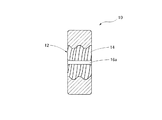
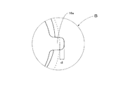
図1乃至図4には、本発明の一実施形態に係るねじ鉄筋用定着ナット(以下、単にナットとも言う。)10が示されている。具体的に、図1はナット10の正面図であり、図2は左側面図であり、図3は、図1におけるA−A面で切断した際に出現する断面を示す説明図である。また、図4は、図1におけるB部を部分的に拡大して表わした説明図である。なお、背面図は正面図と、また、右側面図、平面図及び底面図は左側面図と、それぞれ同一に表わされるため、図示は省略する。
FIG. 1 to FIG. 4 show a fixing nut (hereinafter, also simply referred to as a nut) 10 for a screw reinforcing bar according to an embodiment of the present invention. Specifically, FIG. 1 is a front view of the
かかる図1乃至図4より明らかなように、本発明に係るねじ鉄筋用定着ナット10は、全体として円筒状を呈しており、かかる円筒の中心軸を螺合軸とし、且つ中心軸方向(図1における紙面垂直方向、図3における紙面左右方向。以下、螺合軸方向と言う。)の両端において開口する螺合孔12が、形成されている。なお、円筒の両端における径方向外側の角部は、各々、面取りされている。
As is clear from FIGS. 1 to 4, the
螺合孔12の内周面には、ねじ鉄筋(図示せず)に螺着せしめるための、らせん状の雌ねじ14が形成されている。かかる雌ねじ14は、目的とするねじ鉄筋に容易に螺着せしめることが可能であり、且つ、螺合状態が良好に確保され得るように、ねじ鉄筋の外周面に形成された雄ねじの形状に対応するねじ山高さ及びピッチにて、形成されている。
On the inner peripheral surface of the
そして、本発明に従うねじ鉄筋用定着ナット10にあっては、その螺合孔12の内周面に形成された雌ねじ14を横断するように、螺合軸方向における一方の端から他方の端に向かって延び、且つ、それら両端において外方に開口する二本の凹溝16a、16bが、螺合軸を中心に対向して形成されているところに、大きな技術的特徴が存しているのである。
And, in the
すなわち、そのような二本の凹溝16a、16bが形成されていることにより、例えば鋳造法に従ってねじ鉄筋用定着ナット10を製造すると、ナットの外形を成形するための上型及び下型の型合わせに起因して発生するバリが、ナット10のねじ鉄筋への螺着の際に与える影響を、小さくすることが出来るのであり、また、中子表面の微小なバリに起因する精度不良な雌ねじの形成も、効果的に防止することが可能である。さらに、二本の凹溝16a、16bは螺合軸方向の両端において開口しているため、ナット10をねじ鉄筋に螺着した後、ねじ鉄筋との間に形成される開口部よりグラウト(材)の注入が可能であるところから、ナット10においては、鋳造後にグラウト(材)の注入孔を設ける工程が不要である。従って、本発明に係るねじ鉄筋用定着ナット10を鋳造法によって製造する場合、従来の構造に係るナットでは必要とされていた、中子やナット表面に生じたバリの除去工程が著しく簡易なものとなるか、或いは不要となり、また、グラウト(材)の注入孔の形成工程が不要となるところから、以て、製造コストが低く抑えられることとなるのである。併せて、ねじ鉄筋と螺合した状態でグラウト(材)の注入孔としての役割を発揮する二本の凹溝16a、16bは、螺合軸方向の両端において開口しており、グラウト(材)の注入が容易であると共に、グラウト(材)の注入の度合いも容易に確認することが出来るという利点も、本発明のねじ鉄筋用定着ナット10は有しているのである。
That is, when the two
ここで、図4に示されているように、雌ねじ14を横断する二本の凹溝16a、16bは、その底面が、雌ねじ14を構成する谷部の底面よりも凹んだ位置となるように、換言すれば、雌ねじ14を構成する谷部の底面よりも、二本の凹溝16a、16bにおける各底面の方が、ナット10の径方向外方に突出するように、形成されていることが好ましい。このような構成を採用することにより、上記した本発明による効果をより有利に享受することが可能である。図4(及び図1)において、点線は、雌ねじ14を構成する谷部の底面を示すものであるところ、雌ねじ14を構成する谷部の底面に対する凹溝(16a、16b)の底面の凹み量(図4におけるd)は、小さすぎると本発明の効果を享受することが出来ない恐れがあり、その一方、大きすぎるとナット10の強度が低下する等の問題が発生する恐れがある。このため、凹み量(d)は、ナット10の大きさ等によるものの、一般的には0.5〜3mm程度とされる。なお、二本の凹溝16a、16bにおける各凹み量は、同一であることは勿論のこと、異なっていてもよい。
Here, as shown in FIG. 4, the two
また、二本の凹溝16a、16bの底面における角部は、R形状とされていることが好ましい(図4を参照)。かかる底面の角部がR形状とされていることにより、ナット10が鉄筋コンクリート構造物内で使用された場合に、応力集中による破壊等を有利に防止することが出来る。
Further, it is preferable that the corners on the bottom surfaces of the two
なお、本発明に従うねじ鉄筋用定着ナット10は、従来の、ねじ鉄筋等の異形鉄筋をコンクリートに定着させる際に使用される定着具と同様に、各種の金属材料にて構成されている。
The fixing
ところで、上述してきたねじ鉄筋用定着ナット10は、例えば、以下の手順に従って鋳造法により製造することが可能である。
By the way, the above-described
先ず、外型として、型合わせされた状態においてねじ鉄筋用定着ナット10の外形を与える成形キャビティが形成され、且つ、ナット10における螺合軸の軸中心線を含む平面を型合わせ面とする、一対の上型及び下型が準備される。
First, as the outer die, a molding cavity that gives the outer shape of the
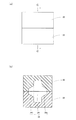
図5には、そのような上型及び下型が示されているところ、図5(a)は、型合わせされた状態にある上型20及び下型22の正面図であり、図5(b)は、同(a)におけるC−C面での断面を示す説明図である。かかる図5(a)、(b)より明らかなように、上型20及び下型22は、型合わせされた状態において、ねじ鉄筋用定着ナット10の外形を与える成形部24と、後述する中子を把持するための把持部26a、26bより構成されるキャビティ28が内部に形成されるように、構成されている。また、上型20により、ナット10における上半分(図1乃至図3における紙面上下方向における上半分)の部位の外形が与えられるように、また、下型22により、ナット10における下半分(図1乃至図3における紙面上下方向における下半分)の部位の外形が与えられるように、各々が構成されていることにより、かかる上型20と下型22との型合わせ面が、鋳造品たるナット10における螺合軸の軸中心線を含む平面と一致する。
FIG. 5 shows such an upper mold and a lower mold. FIG. 5A is a front view of the
なお、上型22及び下型24を構成する材料(鋳型材料)としては、従来より公知の各種鋳型材料であれば、何れも採用することが可能であるが、製造コスト等の観点より、鋳型砂(鋳物砂)が有利に用いられる。また、上型22には、図5(a)、(b)には図示されていないものの、金属溶湯を流し込むための湯口及び湯道が形成されている。
As the material (mold material) constituting the
その一方、ねじ鉄筋用定着ナット10における雌ねじ14及び二本の凹溝16a、16bを形成するための中子が、準備される。図6は、そのような中子を示す説明図であり、図6(a)は中子30の正面図であり、図6(b)は中子30の右側面図である。
On the other hand, a core for forming the
かかる図6より理解されるように、中子30は、ねじ鉄筋用定着ナット10の螺合軸方向に相当する方向の両端に、上述した上型20及び下型22のキャビティ28内にて把持されるための支持部32a、32bを有しており、それら支持部32a、32bの間の部位の外周面には、ナット10の螺合孔12における雌ねじ14に対応する雄ねじ部34と、螺合孔12における二本の凹溝16a、16bに対応する二本の凸条36a、36bとが形成されている。なお、図6(a)、(b)における点線は、後述する成形型を用いて中子30を造型した際の、成形型の型合わせ面(型合わせ線)に対応する部位を示している。
As can be understood from FIG. 6, the
また、図7には、中子30を造型する際に用いられる成形型が示されている。図7(a)は、一対の上型38及び下型40よりなる中子成形型42の、型合わせされた状態を示す正面図であり、図7(b)は、同(a)のD−D面での断面を示す説明図である。
FIG. 7 shows a molding die used when molding the
かかる図7より理解されるように、中子成形型42は、上型38と下型40とが型合わせされた状態において、その内部に、1)中子30における支持部32a、32bを与える部位44a、44bと、2)中子30における雄ねじ部34を与える部位46と、3)中子30における二本の凸条36a、36bを与える部位48a、48bとから構成される成形キャビティが形成されるように、構成されている。また、上型38により、中子30における上半分(図6(a)、(b)における紙面上下方向における上半分)の部位が与えられるように、一方、下型40により、中子30における下半分(図6(a)、(b)における紙面上下方向における下半分)の部位が与えられるように、各々が構成されている。従って、かかる上型38と下型40との型合わせ面は、中子30の軸中心線(換言すれば、鋳造品たるナット10における螺合軸の軸中心線)を含む平面と一致することとなる。
As can be understood from FIG. 7, the
なお、上述した中子成形型42(上型38、下型40)を用いて中子を造型する際には、雄ねじ部34を精度良く形成するために、シェルモールド造型法に従って造型することが好ましい。
When the core is formed using the above-described core forming die 42 (the
以上のようにして準備された一対の上型20及び下型22と、中子30とを、図8に示されるように型合わせを行う。図8は、型合わせされた状態にある上型20、下型22及び中子30についての、図5におけるC−C面に相当する面で切断した際の断面(但し、中子30における雄ねじ部及び凸条は除く)を示す説明図である。かかる型合わせの際には、中子30に形成された二本の凸条36a、36bが、上型20及び下型22の型合わせ面と平行となるように、より詳細には、中子30の二本の凸条36a、36b上における、中子成形型の型合わせ面(型合わせ線)に対応する部位(図8において点線で示す部位)が、上型20及び下型22の型合わせ面と一致するように、実施される。
The pair of
そして、従来より公知の鋳造法に従い、以上のように型合わせされた型の内部に金属溶湯を流し込み、固化せしめ、その後に型ばらしを行うことにより、図1乃至図3に示されるねじ鉄筋用定着ナット10が製造されるのである。
Then, according to a conventionally known casting method, a molten metal is poured into a mold that has been molded as described above, solidified, and then separated from the mold, thereby forming the screw rebar shown in FIGS. 1 to 3. The fixing
このようにして得られるねじ鉄筋用定着ナット10は、螺合孔12の内周面に形成された雌ねじ14を横断するように、二本の凹溝16a、16bが互いに対向して形成されており、かかる二本の凹溝16a、16bの存在により、上型20及び下型22の型合わせに起因するバリは、二本の凹溝16a、16b内に(より詳細には、二本の凹溝16a、16bの各々における螺合方向両端に)発生することとなり、かかるバリが雌ねじ14の形状に及ぼす悪影響、ひいては、ねじ鉄筋への螺着の際に与える影響が小さなものとなっている。また、中子30を、上型20及び下型22に対して所定の位置関係に従って配置し、鋳造を実施することにより、中子30表面の微小なバリに起因する精度不良な雌ねじの形成も、効果的に抑制され得る。更には、螺合孔12の内周面に形成された二本の凹溝16a、16bは両端において開口しており、ナット10をねじ鉄筋に螺着した後、かかる開口部よりグラウト(材)の注入が可能であることから、鋳造後のナットにグラウト(材)の注入孔を設ける工程が不要である。このように、本発明に従うねじ鉄筋用定着ナット10にあっては、鋳造によって製造する場合、従来の構造に係るナットでは必要とされていた、ナット表面のバリを除去する工程等が著しく簡易に、或いは不要となることから、その結果、製造コストが低く抑えられることとなるのである。また、ねじ鉄筋と螺合した状態でグラウト(材)の注入孔としての役割を発揮する二本の凹溝は、螺合軸方向の両端において開口しており、グラウト(材)の注入が容易であると共に、グラウト(材)の注入の度合いも容易に確認することが可能である。
The fixing
以上、本発明の代表的な実施形態の一つについて詳述してきたが、本発明は、上記した具体的態様に限定されるものでは決してなく、本発明の趣旨を逸脱しない限りにおいて、当業者の知識に基づいて、種々なる変更、修正、改良等を加え得るものであることが、理解されるべきである。 As described above, one of the typical embodiments of the present invention has been described in detail. However, the present invention is not limited to the above-described specific embodiments, and those skilled in the art may use the same without departing from the spirit of the present invention. It is to be understood that various changes, modifications, improvements, and the like can be made based on the knowledge of
10 ねじ鉄筋用定着ナット
12 螺合孔
14 雌ねじ
16a、16b 凹溝
20 上型
22 下型
30 中子
34 雄ねじ部
36a、36b 凸条
DESCRIPTION OF
Claims (2)
前記螺合軸方向における一方の端から他方の端に延び、且つそれら両端にて外方に開口する二本の凹溝が、互いに対向して、前記螺合孔の内周面に形成された雌ねじを横断するように形成されていることを特徴とするねじ鉄筋用定着ナット。 Opening at both ends in the screwing axial direction, having a screwing hole formed with an internal thread on the inner peripheral surface,
Two concave grooves extending from one end to the other end in the screwing axial direction and opening outward at both ends are formed on the inner peripheral surface of the screwing hole so as to face each other. An anchor nut for a screw reinforcing bar, which is formed so as to cross an internal thread.
型合わせされた状態において前記ねじ鉄筋用定着ナットの外形を与える成形キャビティが形成され、該ねじ鉄筋用定着ナットにおける螺合軸の軸中心線を含む平面を型合わせ面とする、一対の上型及び下型が準備される一方、
型合わせされた状態において、前記ねじ鉄筋用定着ナットにおける前記雌ねじに対応する雄ねじ形状と、前記二本の凹溝に対応する二本の凸条とを与える成形キャビティを形成し、且つ、該成形キャビティにおける該二本の凸条を与える部位に型合わせ面が位置する一対の成形型を用いて、前記雄ねじ形状及び前記二本の凸条を外周面上に有する中子が造型され、準備された後、
前記中子の外周面上に形成された前記二本の凸条の各々が、前記上型及び下型の型合わせ面と平行となるように、該中子が、該上型及び下型によって形成される成形キャビティ内に配置され、そのように配置された上型、下型及び中子を用いて鋳造が実施されることを特徴とするねじ鉄筋用定着ナットの製造方法。
A method for manufacturing a fixing nut for a screw rebar according to claim 1,
A pair of upper dies, in which a molding cavity that gives an outer shape of the screw nut for a reinforcing screw in the mated state is formed, and a plane including an axis of a screw shaft of the fixing nut for the screw reinforcing is used as a mating surface. And the lower mold is prepared,
In the matched state, a forming cavity is formed that provides a male screw shape corresponding to the female screw and two convex ridges corresponding to the two concave grooves in the fixing nut for the screw rebar, and A core having the male screw shape and the two convex ridges on the outer peripheral surface is molded and prepared using a pair of molding dies in which a mold matching surface is located at a site where the two convex ridges are provided in the cavity. After
The core is formed by the upper mold and the lower mold so that each of the two ridges formed on the outer peripheral surface of the core is parallel to the mold mating surface of the upper mold and the lower mold. A method for manufacturing a fixing nut for a screw rebar, characterized in that casting is performed using an upper mold, a lower mold and a core arranged in a molding cavity to be formed.
Priority Applications (1)
| Application Number | Priority Date | Filing Date | Title |
|---|---|---|---|
| JP2018127227A JP7097550B2 (en) | 2018-07-04 | 2018-07-04 | Fixing nuts for threaded reinforcing bars and their manufacturing methods |
Applications Claiming Priority (1)
| Application Number | Priority Date | Filing Date | Title |
|---|---|---|---|
| JP2018127227A JP7097550B2 (en) | 2018-07-04 | 2018-07-04 | Fixing nuts for threaded reinforcing bars and their manufacturing methods |
Publications (2)
| Publication Number | Publication Date |
|---|---|
| JP2020007729A true JP2020007729A (en) | 2020-01-16 |
| JP7097550B2 JP7097550B2 (en) | 2022-07-08 |
Family
ID=69151002
Family Applications (1)
| Application Number | Title | Priority Date | Filing Date |
|---|---|---|---|
| JP2018127227A Active JP7097550B2 (en) | 2018-07-04 | 2018-07-04 | Fixing nuts for threaded reinforcing bars and their manufacturing methods |
Country Status (1)
| Country | Link |
|---|---|
| JP (1) | JP7097550B2 (en) |
Citations (4)
| Publication number | Priority date | Publication date | Assignee | Title |
|---|---|---|---|---|
| JPS58160612A (en) * | 1982-03-18 | 1983-09-24 | 内外マリアブル株式会社 | Bolt-nut |
| JPH05340070A (en) * | 1992-06-10 | 1993-12-21 | Taisei Denki Kogyo:Yugen | Dry type floor placing method and level adjusting nut to be used therefor |
| JP2003213841A (en) * | 2002-01-28 | 2003-07-30 | Tokyo Tekko Co Ltd | Fixing hardware for screw rebar |
| JP2016003438A (en) * | 2014-06-13 | 2016-01-12 | 東京鐵鋼株式会社 | Fixing hardware for screw rebar and fixing method thereof |
-
2018
- 2018-07-04 JP JP2018127227A patent/JP7097550B2/en active Active
Patent Citations (4)
| Publication number | Priority date | Publication date | Assignee | Title |
|---|---|---|---|---|
| JPS58160612A (en) * | 1982-03-18 | 1983-09-24 | 内外マリアブル株式会社 | Bolt-nut |
| JPH05340070A (en) * | 1992-06-10 | 1993-12-21 | Taisei Denki Kogyo:Yugen | Dry type floor placing method and level adjusting nut to be used therefor |
| JP2003213841A (en) * | 2002-01-28 | 2003-07-30 | Tokyo Tekko Co Ltd | Fixing hardware for screw rebar |
| JP2016003438A (en) * | 2014-06-13 | 2016-01-12 | 東京鐵鋼株式会社 | Fixing hardware for screw rebar and fixing method thereof |
Also Published As
| Publication number | Publication date |
|---|---|
| JP7097550B2 (en) | 2022-07-08 |
Similar Documents
| Publication | Publication Date | Title |
|---|---|---|
| CN101528387A (en) | Mold | |
| CN107008866B (en) | A kind of manufacturing process of cylindrical work pieces | |
| JP7097550B2 (en) | Fixing nuts for threaded reinforcing bars and their manufacturing methods | |
| RU2018143346A (en) | METHOD FOR PRODUCING A VALVE HOUSING HAVING ONE OR MORE CORROSION-RESISTANT INTERNAL SURFACES | |
| JP2009178994A (en) | Manufacturing process of tire vulcanizing mold | |
| CN107073563A (en) | Cast the method for core, the application for casting core and manufacture casting core | |
| KR100205967B1 (en) | Molding method of injection mold for casting | |
| JP4086985B2 (en) | Multi-cylinder internal combustion engine cylinder | |
| CN113909433B (en) | Angle fitting wax mold forming method and forming mold | |
| JP3213992U (en) | Heat treatment tray | |
| JP2000110919A (en) | Molded gear of synthetic resin | |
| CN106734936B (en) | A kind of circular cooler trolley casting method and its compound sand core of casting | |
| EP3895826B1 (en) | Method for producing shaft, and casting mold assembly | |
| JP4033165B2 (en) | Casting cap nut and casting method using cast cap nut | |
| CN108080567B (en) | A water-cooled sand core mold for exhaust pipe | |
| CN222058752U (en) | Pouring structure for preventing flange from shrinking | |
| KR100427310B1 (en) | Die casting method | |
| CN223589722U (en) | Manufacturing mould of precast column and precast column | |
| JP4709562B2 (en) | Mold for casting | |
| JP5414255B2 (en) | Cap injection molding method and cap | |
| JP6050930B2 (en) | Tubular member | |
| JPS6232674Y2 (en) | ||
| JPH0647705Y2 (en) | Mold | |
| KR20030073395A (en) | Sand casting method | |
| JPS6252658B2 (en) |
Legal Events
| Date | Code | Title | Description |
|---|---|---|---|
| A521 | Request for written amendment filed |
Free format text: JAPANESE INTERMEDIATE CODE: A523 Effective date: 20180711 |
|
| A621 | Written request for application examination |
Free format text: JAPANESE INTERMEDIATE CODE: A621 Effective date: 20210415 |
|
| A977 | Report on retrieval |
Free format text: JAPANESE INTERMEDIATE CODE: A971007 Effective date: 20220307 |
|
| A131 | Notification of reasons for refusal |
Free format text: JAPANESE INTERMEDIATE CODE: A131 Effective date: 20220315 |
|
| A521 | Request for written amendment filed |
Free format text: JAPANESE INTERMEDIATE CODE: A523 Effective date: 20220512 |
|
| TRDD | Decision of grant or rejection written | ||
| A01 | Written decision to grant a patent or to grant a registration (utility model) |
Free format text: JAPANESE INTERMEDIATE CODE: A01 Effective date: 20220607 |
|
| A61 | First payment of annual fees (during grant procedure) |
Free format text: JAPANESE INTERMEDIATE CODE: A61 Effective date: 20220616 |
|
| R150 | Certificate of patent or registration of utility model |
Ref document number: 7097550 Country of ref document: JP Free format text: JAPANESE INTERMEDIATE CODE: R150 |
|
| S531 | Written request for registration of change of domicile |
Free format text: JAPANESE INTERMEDIATE CODE: R313531 |
|
| R350 | Written notification of registration of transfer |
Free format text: JAPANESE INTERMEDIATE CODE: R350 |
|
| S533 | Written request for registration of change of name |
Free format text: JAPANESE INTERMEDIATE CODE: R313533 |
|
| R350 | Written notification of registration of transfer |
Free format text: JAPANESE INTERMEDIATE CODE: R350 |
|
| R250 | Receipt of annual fees |
Free format text: JAPANESE INTERMEDIATE CODE: R250 |