JP2020007965A - Internal combustion engine - Google Patents
Internal combustion engine Download PDFInfo
- Publication number
- JP2020007965A JP2020007965A JP2018129364A JP2018129364A JP2020007965A JP 2020007965 A JP2020007965 A JP 2020007965A JP 2018129364 A JP2018129364 A JP 2018129364A JP 2018129364 A JP2018129364 A JP 2018129364A JP 2020007965 A JP2020007965 A JP 2020007965A
- Authority
- JP
- Japan
- Prior art keywords
- crankcase
- internal combustion
- combustion engine
- wall
- crankshaft
- Prior art date
- Legal status (The legal status is an assumption and is not a legal conclusion. Google has not performed a legal analysis and makes no representation as to the accuracy of the status listed.)
- Granted
Links
Images


Classifications
-
- F—MECHANICAL ENGINEERING; LIGHTING; HEATING; WEAPONS; BLASTING
- F02—COMBUSTION ENGINES; HOT-GAS OR COMBUSTION-PRODUCT ENGINE PLANTS
- F02F—CYLINDERS, PISTONS OR CASINGS, FOR COMBUSTION ENGINES; ARRANGEMENTS OF SEALINGS IN COMBUSTION ENGINES
- F02F7/00—Casings, e.g. crankcases
- F02F7/0021—Construction
-
- F—MECHANICAL ENGINEERING; LIGHTING; HEATING; WEAPONS; BLASTING
- F02—COMBUSTION ENGINES; HOT-GAS OR COMBUSTION-PRODUCT ENGINE PLANTS
- F02F—CYLINDERS, PISTONS OR CASINGS, FOR COMBUSTION ENGINES; ARRANGEMENTS OF SEALINGS IN COMBUSTION ENGINES
- F02F7/00—Casings, e.g. crankcases
- F02F7/0002—Cylinder arrangements
- F02F7/0007—Crankcases of engines with cylinders in line
-
- F—MECHANICAL ENGINEERING; LIGHTING; HEATING; WEAPONS; BLASTING
- F16—ENGINEERING ELEMENTS AND UNITS; GENERAL MEASURES FOR PRODUCING AND MAINTAINING EFFECTIVE FUNCTIONING OF MACHINES OR INSTALLATIONS; THERMAL INSULATION IN GENERAL
- F16F—SPRINGS; SHOCK-ABSORBERS; MEANS FOR DAMPING VIBRATION
- F16F15/00—Suppression of vibrations in systems; Means or arrangements for avoiding or reducing out-of-balance forces, e.g. due to motion
- F16F15/22—Compensation of inertia forces
- F16F15/26—Compensation of inertia forces of crankshaft systems using solid masses, other than the ordinary pistons, moving with the system, i.e. masses connected through a kinematic mechanism or gear system
- F16F15/264—Rotating balancer shafts
- F16F15/267—Rotating balancer shafts characterised by bearing support of balancer shafts; Lubrication arrangements
-
- F—MECHANICAL ENGINEERING; LIGHTING; HEATING; WEAPONS; BLASTING
- F16—ENGINEERING ELEMENTS AND UNITS; GENERAL MEASURES FOR PRODUCING AND MAINTAINING EFFECTIVE FUNCTIONING OF MACHINES OR INSTALLATIONS; THERMAL INSULATION IN GENERAL
- F16F—SPRINGS; SHOCK-ABSORBERS; MEANS FOR DAMPING VIBRATION
- F16F15/00—Suppression of vibrations in systems; Means or arrangements for avoiding or reducing out-of-balance forces, e.g. due to motion
- F16F15/22—Compensation of inertia forces
- F16F15/26—Compensation of inertia forces of crankshaft systems using solid masses, other than the ordinary pistons, moving with the system, i.e. masses connected through a kinematic mechanism or gear system
- F16F15/264—Rotating balancer shafts
- F16F15/268—Hollow shafts
Landscapes
- Engineering & Computer Science (AREA)
- General Engineering & Computer Science (AREA)
- Mechanical Engineering (AREA)
- Physics & Mathematics (AREA)
- Acoustics & Sound (AREA)
- Aviation & Aerospace Engineering (AREA)
- Chemical & Material Sciences (AREA)
- Combustion & Propulsion (AREA)
- Cylinder Crankcases Of Internal Combustion Engines (AREA)
Abstract
Description
本発明は、回転軸線回りに回転自在にクランク軸を支持するクランクケースと、クランクケースの外側でクランク軸の一端に連結される発電機と、クランクケースに形成されて、クランクケースに外側から結合される発電機カバーとの間で発電機を収容する壁体とを備える内燃機関に関する。 The present invention provides a crankcase that supports a crankshaft rotatably around a rotation axis, a generator connected to one end of the crankshaft outside the crankcase, and a crankcase formed on the crankcase and coupled to the crankcase from outside. And a wall housing the generator between the generator cover and the internal combustion engine.
特許文献1は、クランクケースの外側でクランク軸の一端に連結される発電機を備える内燃機関を開示する。クランクケースには、クランクケースの壁体との間で発電機の収容空間を区画する発電機カバーが結合される。発電機の収容空間では、クランク軸の回転軸線に平行な軸心を有するバランサー軸の一端がクランクケースの壁体から突出する。 Patent Literature 1 discloses an internal combustion engine including a generator connected to one end of a crankshaft outside a crankcase. A generator cover that divides a housing space of the generator between the crankcase and a wall of the crankcase is coupled to the crankcase. In the housing space of the generator, one end of the balancer shaft having an axis parallel to the rotation axis of the crankshaft protrudes from the wall of the crankcase.
バランサー軸には従動ギアおよび偏心ウエイトが支持される。従動ギアは、クランク軸に固定される駆動ギアに噛み合う。偏心ウエイトは、従動ギアの働きでクランク軸の回転に連動して回転し、内燃機関の振動を低減する。 A driven gear and an eccentric weight are supported on the balancer shaft. The driven gear meshes with a drive gear fixed to the crankshaft. The eccentric weight rotates in conjunction with the rotation of the crankshaft by the function of the driven gear, and reduces the vibration of the internal combustion engine.
バランサー軸は両持ち支持されることから、バランサー軸がクランク軸の軸方向に発電機の収容空間から遠ざかるには、壁体の肉厚化が要求されてしまう。壁体の肉厚化は内燃機関の重量増を招く。その一方で、壁体の肉厚化を回避しつつバランサー軸の短縮化を実現すると、バランサー軸は発電機に向かって偏って配置されることから、内燃機関の重量バランスは崩れてしまう。 Since the balancer shaft is supported at both ends, it is necessary to increase the wall thickness in order for the balancer shaft to move away from the housing space of the generator in the axial direction of the crankshaft. Increasing the wall thickness causes an increase in the weight of the internal combustion engine. On the other hand, if the shortening of the balancer shaft is realized while avoiding the increase in the wall thickness, the weight balance of the internal combustion engine will be lost because the balancer shaft is arranged to be biased toward the generator.
本発明は、上記実状に鑑みてなされたもので、可及的にバランサー軸を短縮し、重量バランスを崩さずに軽量化を実現することができる内燃機関を提供することを目的とする。 The present invention has been made in view of the above circumstances, and an object of the present invention is to provide an internal combustion engine capable of shortening a balancer shaft as much as possible and realizing a weight reduction without breaking a weight balance.
本発明の第1側面によれば、回転軸線回りに回転自在にクランク軸を支持するクランクケースと、前記クランクケースの外側で前記クランク軸の一端に連結される発電機と、前記クランクケースに形成されて、前記クランクケースに外側から結合される発電機カバーとの間で前記発電機を収容する壁体と、前記クランクケースに形成されて、前記クランク軸の軸方向に前記壁体から離れた位置で、前記クランクケースの外面に接する空間を挟んで前記壁体に向き合うケーシング壁を有するケーシングと、前記クランク軸の回転軸線に平行な軸心を有し、前記空間内に前記ケーシング壁から一端を突出させつつ前記ケーシングに回転可能に支持されるバランサー軸とを備える内燃機関が提供される。 According to a first aspect of the present invention, a crankcase that supports a crankshaft so as to be rotatable around a rotation axis, a generator connected to one end of the crankshaft outside the crankcase, and a crankcase formed on the crankcase. A wall housing the generator between a generator cover coupled to the crankcase from the outside, and a wall formed on the crankcase and separated from the wall in an axial direction of the crankshaft. A casing having a casing wall facing the wall body with a space in contact with the outer surface of the crankcase at a position, and having an axis parallel to a rotation axis of the crankshaft, and one end of the casing wall in the space. And a balancer shaft rotatably supported by the casing while protruding.
第2側面によれば、第1側面の構成に加えて、内燃機関は、複数のシリンダーを区画するシリンダーブロックと、前記クランクケースに形成されて、個々の前記シリンダーに対応して前記クランク軸のジャーナルを支持する隔壁とを備え、前記ケーシングは、内側に位置する前記シリンダーに対応する前記隔壁から連続して前記バランサー軸の他端を支持する。 According to the second aspect, in addition to the configuration of the first aspect, the internal combustion engine further includes a cylinder block that defines a plurality of cylinders, and the crankshaft formed in the crankcase and corresponding to each of the cylinders. A partition supporting the journal, wherein the casing supports the other end of the balancer shaft continuously from the partition corresponding to the cylinder positioned inside.
第3側面によれば、第1または第2側面の構成に加えて、前記壁体には、前記バランサー軸に同軸に前記バランサー軸の外径よりも大径の貫通孔が形成される。 According to the third aspect, in addition to the configuration of the first or second aspect, a through hole having a diameter larger than the outer diameter of the balancer shaft is formed in the wall body coaxially with the balancer shaft.
第4側面によれば、第3側面の構成に加えて、前記貫通孔には、前記バランサー軸に関連して前記ケーシングに穿たれる支持穴の穿孔具が挿入可能である。 According to the fourth aspect, in addition to the configuration of the third aspect, a punch for a support hole formed in the casing in relation to the balancer shaft can be inserted into the through hole.
第5側面によれば、第3または第4側面の構成に加えて、内燃機関は、前記クランクケースの外側から前記貫通孔に挿入され前記貫通孔を塞ぐ栓部材と、前記発電機カバーに形成されて、前記クランクケースの外側から前記クランクケースに前記発電機カバーが結合される際に前記栓部材に接触する抜け止めとを備える。 According to the fifth aspect, in addition to the configuration of the third or fourth aspect, the internal combustion engine includes a plug member inserted into the through-hole from the outside of the crankcase to close the through-hole, and formed on the generator cover. And a stopper that comes into contact with the plug member when the generator cover is coupled to the crankcase from outside the crankcase.
第6側面によれば、第1〜第5側面のいずれか1の構成に加えて、前記バランサー軸は、側面視で前記発電機のローターの外縁よりも外側に配置される。 According to the sixth aspect, in addition to the configuration of any one of the first to fifth aspects, the balancer shaft is disposed outside the outer edge of the rotor of the generator in side view.
第7側面によれば、第1〜第6側面のいずれか1の構成に加えて、前記クランクケースは、割り面で分割される上体および下体を有し、前記バランサー軸の軸心は、前記割り面よりも下方であって、前記クランク軸よりも前方であって、前記発電機のローターの下端に接する水平面よりも上方に配置される。 According to the seventh aspect, in addition to the configuration of any one of the first to sixth aspects, the crankcase has an upper body and a lower body divided by a split surface, and the axis of the balancer shaft is: The generator is disposed below the split plane, forward of the crankshaft, and above a horizontal plane in contact with a lower end of a rotor of the generator.
第1側面によれば、バランサー軸は、発電機の収容空間を形成する壁体から離れて配置されてケーシングに支持されるので、壁体の肉厚化は阻止されることができる。内燃機関の軽量化は実現されることができる。加えて、バランサー軸が短縮されても、内燃機関全体に対してバランサー軸は偏って配置される必要はなく、内燃機関の重量バランスは良好に維持されることができる。 According to the first aspect, the balancer shaft is disposed away from the wall forming the housing space of the generator and is supported by the casing, so that the wall can be prevented from being thickened. Lightening of the internal combustion engine can be realized. In addition, even if the balancer shaft is shortened, the balancer shaft does not need to be arranged eccentrically with respect to the entire internal combustion engine, and a good weight balance of the internal combustion engine can be maintained.
第2側面によれば、重量物であるバランサー軸は内燃機関の質量重心に近づき配置されることができるので、内燃機関の重量バランスは良好に維持されることができる。 According to the second aspect, since the balancer shaft, which is a heavy object, can be arranged close to the center of gravity of the internal combustion engine, the weight balance of the internal combustion engine can be well maintained.
第3側面によれば、発電機カバーが外されると、壁体の貫通孔からケーシングに向かってバランサー軸は挿入されることができ、バランサー軸は調整されることができる。 According to the third aspect, when the generator cover is removed, the balancer shaft can be inserted from the through hole of the wall toward the casing, and the balancer shaft can be adjusted.
第4側面によれば、ケーシングの支持穴の中心軸が壁体に重なっても、貫通孔に穿孔具が挿入されることで、支持穴は容易に加工されることができる。 According to the fourth aspect, even if the center axis of the support hole of the casing overlaps the wall, the support hole can be easily processed by inserting the punch into the through hole.
第5側面によれば、栓部材はクランクケースの外面に接する空間から発電機の収容空間に向かって塵埃の進入を防止することができる。発電機カバーがクランクケースに結合されると、発電機カバーの抜け止めは壁体から栓部材の離脱を防止することができる。 According to the fifth aspect, the plug member can prevent dust from entering from the space in contact with the outer surface of the crankcase toward the housing space of the generator. When the generator cover is coupled to the crankcase, the stopper of the generator cover prevents the plug member from being detached from the wall.
第6側面によれば、クランク軸に発電機のローターが取り付けられた後でも、貫通孔を通じてバランサー軸の調整は実現されることができる。 According to the sixth aspect, even after the rotor of the generator is mounted on the crankshaft, the adjustment of the balancer shaft can be realized through the through hole.
第7側面によれば、バランサー軸はクランク軸に近づき配置されることができ、バランサー軸は内燃機関の重心に近づくことから、内燃機関の重量バランスは良好に確立されることができる。 According to the seventh aspect, the balancer shaft can be arranged closer to the crankshaft, and since the balancer shaft approaches the center of gravity of the internal combustion engine, the weight balance of the internal combustion engine can be well established.
以下、添付図面を参照しつつ本発明の一実施形態を説明する。ここで、車体の上下前後左右は自動二輪車に乗車した乗員の目線に基づき規定されるものとする。 Hereinafter, an embodiment of the present invention will be described with reference to the accompanying drawings. Here, it is assumed that the up, down, front, rear, left and right of the vehicle body are defined based on the eyes of the occupant riding the motorcycle.
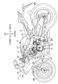
図1は本発明の一実施形態に係る鞍乗り型車両である自動二輪車の全体像を概略的に示す。自動二輪車11は、車体フレーム12と、車体フレーム12に装着された車体カバー13とを備える。車体カバー13は、前方から車体フレーム12を覆うフロントカウル14と、燃料タンク15の外面から前方に連続し、燃料タンク15の後方の乗員シート16に接続されるタンクカバー17とを有する。燃料タンク15に燃料は貯留される。自動二輪車11の運転にあたって乗員は乗員シート16を跨ぐ。
FIG. 1 schematically shows an overall image of a motorcycle which is a saddle-ride type vehicle according to an embodiment of the present invention. The
車体フレーム12は、ヘッドパイプ18と、ヘッドパイプ18から後ろ下がりに延びて、後下端にピボットフレーム19を有する左右1対のメインフレーム21と、メインフレーム21の下方の位置でヘッドパイプ18から下方に延び、メインフレーム21に一体化されるダウンフレーム22と、メインフレーム21の湾曲域21aから後上がりに延びトラス構造を構成する左右のシートフレーム23とを有する。シートフレーム23に乗員シート16は支持される。
The
ヘッドパイプ18には操向自在にフロントフォーク24が支持される。フロントフォーク24には車軸25回りで回転自在に前輪WFが支持される。フロントフォーク24の上端には操向ハンドル26が結合される。運転者は自動二輪車11の運転にあたって操向ハンドル26の左右端のグリップを握る。
A
車両の後方で車体フレーム12にはピボット27回りで上下に揺動自在にスイングアーム28が連結される。スイングアーム28の後端に車軸29回りで回転自在に後輪WRが支持される。前輪WFと後輪WRとの間で車体フレーム12には後輪WRに伝達される駆動力を生成する内燃機関31が搭載される。内燃機関31の動力は伝動装置を経て後輪WRに伝達される。
A
内燃機関31は、後壁の上端および下端にメインフレーム21に連結されるエンジンハンガー32a、32bを有し、回転軸線Rx回りで動力を出力するクランクケース32と、クランクケース32に結合されて、回転軸線Rxに直交する鉛直面内に位置して水平面に対して起立するシリンダー軸線Cを有するシリンダーブロック33と、シリンダーブロック33の上端に結合されて、前壁にダウンフレーム22に連結されるエンジンハンガー34cを有し、動弁機構を支持するシリンダーヘッド34と、シリンダーヘッド34の上端に結合されて、シリンダーヘッド34上の動弁機構を覆うヘッドカバー35とを備える。
The
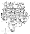
図2に示されるように、クランクケース32は、水平面Dp内に規定される割り面37で上体38aおよび下体38bに分割される。クランクケース32には、割り面37を含む水平面Dpに対して所定の傾斜角で交差する仮想平面Mp内に規定される合わせ面39で下方からオイルパン41が結合される。仮想平面Mpと水平面Dpとの交線はクランク軸の回転軸線Rxに平行に設定される。合わせ面39は前縁から後ろ下がりに傾斜する。合わせ面39の後縁は、クランクケース32の下端に配置されるエンジンハンガー32bの下方に位置する。
As shown in FIG. 2, the
シリンダーブロック33にはシリンダー軸線Cに沿ってピストン42の線形往復運動を案内するシリンダー43が形成される。ここでは、シリンダーブロック33には回転軸線Rxに沿って4つのシリンダー43が並び、内燃機関31はいわゆる直列4気筒に構成される。ピストン42とシリンダーヘッド43との間に燃焼室44が区画される。カムシャフトの回転に応じて開閉する吸気弁45aおよび排気弁45bの働きで燃焼室44に混合気が導入され燃焼後の排ガスは燃焼室44から排気される。
The
図3に示されるように、クランクケース32には回転軸線Rx回りで回転自在にクランク軸46が支持される。クランク軸46は、回転軸線Rxに同軸に形成されるジャーナル47と、隣接するジャーナル47の間に配置されて、回転軸線Rxに平行に延びクランクウエブを相互に結合するクランクピン48を有するクランク49とを備える。クランクケース32には、個々のシリンダー43に対応して滑り軸受で回転自在にジャーナル47を個別に支持する隔壁51が形成される。クランクピン48には、ピストン42から延びるコネクティングロッド52の大端部が回転自在に連結される。コネクティングロッド52はピストン42の線形往復運動をクランク軸46の回転運動に変換する。
As shown in FIG. 3, a
クランク軸46の一端は、クランクケース32の左側面を形成する隔壁51から外側に突出する。クランク軸46の一端にはACG(交流発電機)53が接続される。クランクケース32の左側面にはクランクケース32との間にACG53を収容するACGカバー54が結合される。
One end of the
ACG53は、ACGカバー54に固定されるステーター55と、クランクケース32から突き出るクランク軸46の一端に相対回転不能に結合されるローター56とを備える。ステーター55は、クランク軸46周りで周方向に配列されて、ステーターコアに巻き付けられる複数のコイル55aを有する。ローター56は、ステーター55を囲む環状の軌道に沿って周方向に配列される複数の磁石56aを有する。クランク軸46が回転すると、コイル55aに対して磁石56aが相対変位し、ACG53は発電する。
The
クランク軸46の他端は、クランクケース32の右側面を形成する隔壁51から外側に突出する。クランク軸46の他端にはカムシャフトに動力を伝達する動弁機構57が連結される。動弁機構57は、クランク軸46に同軸に固定される駆動カムギア57aと、カムシャフトに固定される従動カムギア(図示されず)と、駆動カムギア57aから従動カムギアまで順番に噛み合って駆動カムギア57aから従動カムギアまで動力を伝達する複数のギアで構成されるカムギア列57bとを備える。クランクケース32の右側面にはクランクケース32との間に駆動カムギア57aを収容する動弁機構カバー58が結合される。ACGカバー54および動弁機構カバー58はクランクケース32の外面に被さってクランク軸46を収容するクランク室CRを区画する。動弁機構57は、駆動カムギア57a、従動カムギアおよびカムギア列57bに代えて、駆動スプロケット、従動スプロケットおよびカムチェーンを備えてもよい。
The other end of the
内燃機関31にはドグクラッチ式の多段変速機(以下「変速機」)59が組み込まれる。変速機59は、クランク室CRから連続してクランクケース32に区画される変速機室61に収容される。変速機59はクランク軸46の軸心に平行な軸心を有するメイン軸62およびカウンター軸63を備える。メイン軸62およびカウンター軸63は転がり軸受64a、64b、65a、65bで回転自在にクランクケース32に支持される。
A dog clutch type multi-stage transmission (hereinafter referred to as “transmission”) 59 is incorporated in the
メイン軸62およびカウンター軸63には複数の変速ギア66が支持される。変速ギア66は軸受64a、64b;65a、65b同士の間に配置されて変速機室61に収容される。変速ギア66は、メイン軸62またはカウンター軸63に同軸に相対回転自在に支持される回転ギア66aと、メイン軸62に相対回転不能に固定されて、対応する回転ギア66aに噛み合う固定ギア66bと、メイン軸62またはカウンター軸63に相対回転不能かつ軸方向変位自在に支持されて、対応する回転ギア66aに噛み合うシフトギア66cとを含む。回転ギア66aおよび固定ギア66bの軸方向変位は規制される。軸方向変位を通じてシフトギア66cが回転ギア66aに連結されると、回転ギア66aとメイン軸62またはカウンター軸63との相対回転は規制される。シフトギア66cが他軸の固定ギア66bに噛み合うと、メイン軸62およびカウンター軸63の間で回転動力は伝達される。他軸の固定ギア66bに噛み合う回転ギア66aにシフトギア66cが連結されると、メイン軸62およびカウンター軸63の間で回転動力は伝達される。こうしてメイン軸62とカウンター軸63との間で特定の変速ギア66が噛み合うことで規定の減速比でメイン軸62からカウンター軸63に回転動力は伝達される。
A plurality of transmission gears 66 are supported on the main shaft 62 and the
メイン軸62の一端はクランクケース32の右側面から外側に突出する。メイン軸62の一端には、クランクケース32の外側で、クランク軸46のプライマリ駆動ギア67に噛み合うプライマリ従動ギア68が相対回転自在に同軸に支持される。プライマリ駆動ギア67は例えばクランク軸46のクランク49に一体に形成される。
One end of the main shaft 62 projects outward from the right side surface of the
メイン軸62上でプライマリ従動ギア68には摩擦クラッチ71が連結される。クランクケース32の右側面には、クランクケース32との間に摩擦クラッチ71を収容するクラッチカバー72が結合される。摩擦クラッチ71はクラッチアウター71aおよびクラッチハブ71bを備える。クラッチアウター71aにプライマリ従動ギア68は連結される。クラッチレバーの操作に応じて摩擦クラッチ71ではクラッチアウター71aおよびクラッチハブ71bの間で連結および切断が切り替えられる。
A
カウンター軸63には、クランクケース32の外側に配置される伝動装置73の駆動スプロケット73aが結合される。駆動スプロケット73aには駆動チェーン73bが巻き掛けられる。駆動チェーン73bは駆動スプロケット73aの回転動力を後輪WRに伝達する。
A
クランク軸46には、ACG53のローター56とクランクケース32との間で、クランク軸46に同軸に環状に配置されるリラクター74を有するパルサーリング75が取り付けられる。パルサーリング75は例えばACG53のローター56に固定される(一体化される)。リラクター74はローター56の外周よりも径方向外側に突き出る。パルサーリング75は例えば磁性体から形成される。
A
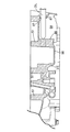
図4に示されるように、クランクケース32には、クランクケース32の左側面から起立して、クランク軸46の回転軸線Rx回りでローター56を囲む囲み壁76が形成される。囲み壁76には、検知端77aでリラクター74の軌道に向き合わせられてリラクター74の動きに応じてパルス信号を生成するパルサーセンサー77が取り付けられる。パルサーセンサー77は、クランク軸46の回転軸線Rxを含む水平面Hrよりも上方で囲み壁76に穿たれるセンサー孔78に外側から差し込まれて、隔壁51およびACGカバー54に挟まれる空間に検知端77aを臨ませるセンサー本体79と、センサー本体79に結合されて、センサー孔78の外側で囲い壁76の外面に重ねられてクランクケース32に締結される取り付け片81とを備える。
As shown in FIG. 4, a surrounding
パルサーセンサー77の検知端77aは、クランク軸46の回転軸線Rxに直交する平面に沿って等間隔で配置されるリラクター74の軌道に向き合わせられる。パルサーセンサー77は、例えば磁気抵抗効果素子の働きで、リラクター74の軌道上で検出される磁性体の有無に応じて電気信号すなわちパルス信号を出力する。パルス信号でクランク軸46の角位置は特定される。パルサーセンサー77では最も感度の高い検出軸線77bが回転軸線Rxに指向する。
The
図2に示されるように、クランクケース32には、クランク軸46の前方に配置されてクランク軸46に連動する2次バランサー82が収容される。2次バランサー82は、クランク軸46の回転軸線Rxに平行な軸心回りで回転自在にバランサー軸83に支持される偏心ウエイト84と、偏心ウエイト84に同軸に回転自在にバランサー軸83に支持されて、偏心ウエイト84に連結されるバランサー従動ギア85aとを備える。バランサー従動ギア85aは偏心ウエイト84上に支持され固定されればよい。バランサー従動ギア85aはクランク軸46に固定される駆動ギア85bに噛み合う。バランサー従動ギア85aは駆動ギア85bの駆動力を受けてバランサー軸83回りで偏心ウエイト84の回転を引き起こす。図3に示されるように、駆動ギア85bはクランク軸46のクランク49に一体に形成される。
As shown in FIG. 2, the
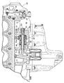
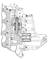
図5に示されるように、クランクケース32の前壁には、クランク室CRから連続して、偏心ウエイト84およびバランサー従動ギア85aを収容する空間を区画するケーシング86が形成される。図6に示されるように、クランクケース32には、隔壁51から連続して、ACGカバー54との間でACG53を収容する壁体87が形成される。
As shown in FIG. 5, a
ケーシング86は、クランク軸46の軸方向に壁体87から離れた位置で、クランクケース32の前壁に接する空間88を挟んで壁体87に向き合う第1ケーシング壁89と、偏心ウエイト84およびバランサー従動ギア85aの収容空間を挟んで第1ケーシング壁89に向き合わせられる第2ケーシング壁91とを有する。第1ケーシング壁89は、外側に位置するシリンダー43と、内側に位置するシリンダー43との間に配置される隔壁51から連続する。第2ケーシング壁91は、内側に位置するシリンダー43の間に配置される隔壁51から連続する。
The
バランサー軸83は、その一端および他端に、クランク軸46の回転軸線Rxに平行であって偏心ウエイト84の回転軸線から偏心した軸心を有する第1支軸92aおよび第2支軸92bを有する。第1支軸92aは、第1ケーシング壁89に穿たれる支持孔93に挿入され支持される。第2支軸92bは、第2ケーシング壁91に穿たれる支持穴94に挿入され支持される。
The
バランサー軸83の一端は、第1ケーシング壁89から空間88に突出し、先端で壁体87に向き合わせられる。壁体87に向き合う先端には、第1支軸92aおよび第2支軸92bの軸心回りでバランサー軸83を回転させる際に用いられる工具用の溝95が形成される。偏心軸96に転がり軸受を介して偏心ウエイト84は装着される。第2支軸92bおよび偏心軸96は第1支軸92aの円筒面で規定される仮想円筒面よりも内側に配置される。
One end of the
壁体87には、バランサー軸83の第1支軸92aに同軸にバランサー軸83の外径よりも大径の貫通孔97が形成される。貫通孔97はACG53側に大径部を有する。貫通孔97の大径部には、クランクケース32の外側から貫通孔97を塞ぐ栓部材98が液密に挿入される。発電機カバー54には、クランクケース32の外側からクランクケース32に発電機カバー54が結合される際に栓部材98に接触する抜け止め99が形成される。
A through
図4に示されるように、バランサー軸83は、側面視でACG53のローター56の外縁よりも外側に配置される。バランサー軸83の軸心は、割り面37よりも下方であって、クランク軸46よりも前方であって、ACG53のローター56の下端に接する水平面HLよりも上方に配置される。
As illustrated in FIG. 4, the
次に本実施形態の動作を説明する。内燃機関31が動作すると、シリンダー43内でシリンダー軸線Cに沿ってピストン42は線形往復運動する。コネクティングロッド52の働きでクランク軸46は回転軸線Rx回りで回転する。このとき、クランク軸46の駆動ギア85bから2次バランサー82のバランサー従動ギア85aに所定の減速比でクランク軸46の回転力は伝達される。バランサー軸82の偏心軸96回りで偏心ウエイト84は回転する。偏心ウエイト84は、バランサー従動ギア85の働きでクランク軸46の回転に連動して回転し、内燃機関31の振動を低減する。
Next, the operation of the present embodiment will be described. When the
本実施形態に係る内燃機関31では、ケーシング86は、クランク軸46の軸方向に壁体87から離れた位置で空間88を挟んで壁体87に向き合う第1ケーシング壁89を有する。2次バランサー82のバランサー軸83は、クランク軸46の回転軸線Rxに平行な軸心を有し、クランクケース32の外面に接する空間88内に第1ケーシング壁89から一端を突出させつつケーシング86に回転可能に支持される。バランサー軸83は、ACG53の収容空間を形成する壁体87から離れて配置されてケーシング86に支持されるので、壁体87の肉厚化は阻止される。内燃機関31の軽量化は実現される。加えて、バランサー軸83が短縮されても、内燃機関31全体に対してバランサー軸83は偏って配置される必要はなく、内燃機関31の重量バランスは良好に維持される。
In the
本実施形態では、ケーシング86は、内側に位置するシリンダー43に対応する隔壁51から連続してバランサー軸83の他端を支持する。重量物であるバランサー軸83は内燃機関42の質量重心に近づき配置されるので、内燃機関42の重量バランスは良好に維持される。
In the present embodiment, the
本実施形態では、バランサー軸83の軸心は、割り面37よりも下方であって、クランク軸46よりも前方であって、ACG53のローター56の下端に接する水平面HLよりも上方に配置される。バランサー軸83はクランク軸46に近づき配置され、バランサー軸83は内燃機関31の重心に近づくことから、内燃機関31の重量バランスは良好に確立される。
In the present embodiment, the axis of the
内燃機関31の製造にあたって、第1ケーシング壁89に支持孔93は穿たれる。このとき、図7に示されるように、ドリル(穿孔具)DLは壁体87の貫通孔97から挿入されて第1ケーシング壁89に達する。次に、第2ケーシング壁91に支持穴94は穿たれる。このとき、ドリルは壁体87の貫通孔97および第1ケーシング壁89の支持孔93を貫通する。したがって、貫通孔97の働きで良好に支持孔93および支持穴94は形成されることができる。ケーシング86の支持穴94の中心軸が壁体87に重なっても、貫通孔97にドリルが挿入されることで、支持穴94は容易に加工される。
In manufacturing the
支持孔93から支持穴94に向かってバランサー軸83は挿入される。ACGカバー54に向き合う壁体87には、バランサー軸83に同軸にバランサー軸83の外径よりも大径の貫通孔97が形成されることから、壁体87の貫通孔97からケーシング86に向かってバランサー軸83は挿入されることができる。
The
貫通孔97は栓部材98で塞がれる。栓部材98はクランクケース32の外面に接する空間88からACG53の収容空間に向かって塵埃の進入を防止する。クランクケース32にACGカバー54が結合されると、ACGカバー54の抜け止め99は栓部材98に接触する。こうしてACGカバー54がクランクケース32に結合されると、ACGカバー54の抜け止め99は壁体87から栓部材98の離脱を防止する。
The through
バランサー軸83はケーシング86に回転可能に支持される。バランサー軸83は、側面視でACG53のローター56の外縁よりも外側に配置されることから、ACGカバー54が外されると、図8に示されるように、貫通孔97から挿入される工具TLの先端はバランサー軸83先端の溝95に達することができる。こうしてバランサー軸83が回転すると、偏心軸96の働きでバランサー従動ギア85aは駆動ギア85bに近づいたり遠ざかったりすることができる。バランサー従動ギア85aおよび駆動ギア85bの間でバックラッシュは調整される。貫通孔97からクランク軸46にACG53のローター56が取り付けられた後でも、貫通孔97を通じてバランサー軸83の調整は実現される。
The
31…内燃機関、32…クランクケース、33…シリンダーブロック、37…割り面、38a…(クランクケースの)上体、38b…(クランクケースの)下体、43…シリンダー、46…クランク軸、47…ジャーナル、51…隔壁、53…発電機(ACG)、54…発電機(ACG)カバー、83…バランサー軸、86…ケーシング、87…壁体、88…(クランクケースの外面に接する)空間、89…ケーシング壁、94…支持穴、97…貫通孔、98…栓部材、99…抜け止め、HL…(ローターの下端に接する)水平面、Rx…(クランク軸の)回転軸線、TL…工具。 31: internal combustion engine, 32: crankcase, 33: cylinder block, 37: split surface, 38a: upper body (of crankcase), 38b: lower body (of crankcase), 43: cylinder, 46: crankshaft, 47 ... Journal, 51 ... Partition wall, 53 ... Generator (ACG), 54 ... Generator (ACG) cover, 83 ... Balancer shaft, 86 ... Casing, 87 ... Wall, 88 ... Space (in contact with the outer surface of the crankcase), 89 ... casing wall, 94 ... support hole, 97 ... through hole, 98 ... plug member, 99 ... stopper, HL ... horizontal surface (contacting the lower end of the rotor), Rx ... rotation axis (of the crankshaft), TL ... tool.
Claims (7)
前記クランクケース(32)の外側で前記クランク軸(46)の一端に連結される発電機(53)と、
前記クランクケース(32)に形成されて、前記クランクケース(32)に外側から結合される発電機カバー(54)との間で前記発電機(53)を収容する壁体(87)と、
前記クランクケース(32)に形成されて、前記クランク軸(46)の軸方向に前記壁体(87)から離れた位置で、前記クランクケース(32)の外面に接する空間(88)を挟んで前記壁体(87)に向き合うケーシング壁(89)を有するケーシング(86)と、
前記クランク軸(46)の回転軸線(Rx)に平行な軸心を有し、前記空間(88)内に前記ケーシング壁(89)から一端を突出させつつ前記ケーシング(86)に回転可能に支持されるバランサー軸(83)と、
を備えることを特徴とする内燃機関。 A crankcase (32) for supporting a crankshaft (46) rotatably about a rotation axis (Rx);
A generator (53) connected to one end of the crankshaft (46) outside the crankcase (32);
A wall (87) formed on the crankcase (32) and accommodating the generator (53) between the generator cover (54) and the generator cover (54) coupled from the outside to the crankcase (32);
A space (88) formed in the crankcase (32) and in contact with the outer surface of the crankcase (32) at a position separated from the wall (87) in the axial direction of the crankshaft (46). A casing (86) having a casing wall (89) facing the wall (87);
It has an axis parallel to the rotation axis (Rx) of the crankshaft (46) and is rotatably supported by the casing (86) while projecting one end from the casing wall (89) into the space (88). Balancer axis (83) to be
An internal combustion engine comprising:
Priority Applications (3)
| Application Number | Priority Date | Filing Date | Title |
|---|---|---|---|
| JP2018129364A JP6727256B2 (en) | 2018-07-06 | 2018-07-06 | Internal combustion engine |
| US16/450,025 US10883445B2 (en) | 2018-07-06 | 2019-06-24 | Internal combustion engine |
| DE102019118236.0A DE102019118236B4 (en) | 2018-07-06 | 2019-07-05 | Combustion engine with crankshaft and balance shaft |
Applications Claiming Priority (1)
| Application Number | Priority Date | Filing Date | Title |
|---|---|---|---|
| JP2018129364A JP6727256B2 (en) | 2018-07-06 | 2018-07-06 | Internal combustion engine |
Publications (2)
| Publication Number | Publication Date |
|---|---|
| JP2020007965A true JP2020007965A (en) | 2020-01-16 |
| JP6727256B2 JP6727256B2 (en) | 2020-07-22 |
Family
ID=68943827
Family Applications (1)
| Application Number | Title | Priority Date | Filing Date |
|---|---|---|---|
| JP2018129364A Active JP6727256B2 (en) | 2018-07-06 | 2018-07-06 | Internal combustion engine |
Country Status (3)
| Country | Link |
|---|---|
| US (1) | US10883445B2 (en) |
| JP (1) | JP6727256B2 (en) |
| DE (1) | DE102019118236B4 (en) |
Citations (3)
| Publication number | Priority date | Publication date | Assignee | Title |
|---|---|---|---|---|
| JPS6045842U (en) * | 1983-09-06 | 1985-03-30 | スズキ株式会社 | 4-cycle engine cylinder head |
| JPH09329194A (en) * | 1996-06-11 | 1997-12-22 | Honda Motor Co Ltd | Engine balancer device |
| JP2016061214A (en) * | 2014-09-18 | 2016-04-25 | 本田技研工業株式会社 | Oil supply structure for water-cooled internal combustion engine |
Family Cites Families (2)
| Publication number | Priority date | Publication date | Assignee | Title |
|---|---|---|---|---|
| JPS5847688A (en) | 1981-09-18 | 1983-03-19 | 本田技研工業株式会社 | Master cylinder for motorcycle braking devices |
| JP5847688B2 (en) | 2012-11-08 | 2016-01-27 | 本田技研工業株式会社 | Balancer device for parallel two-cylinder internal combustion engine |
-
2018
- 2018-07-06 JP JP2018129364A patent/JP6727256B2/en active Active
-
2019
- 2019-06-24 US US16/450,025 patent/US10883445B2/en active Active
- 2019-07-05 DE DE102019118236.0A patent/DE102019118236B4/en active Active
Patent Citations (3)
| Publication number | Priority date | Publication date | Assignee | Title |
|---|---|---|---|---|
| JPS6045842U (en) * | 1983-09-06 | 1985-03-30 | スズキ株式会社 | 4-cycle engine cylinder head |
| JPH09329194A (en) * | 1996-06-11 | 1997-12-22 | Honda Motor Co Ltd | Engine balancer device |
| JP2016061214A (en) * | 2014-09-18 | 2016-04-25 | 本田技研工業株式会社 | Oil supply structure for water-cooled internal combustion engine |
Also Published As
| Publication number | Publication date |
|---|---|
| DE102019118236B4 (en) | 2021-12-30 |
| US10883445B2 (en) | 2021-01-05 |
| JP6727256B2 (en) | 2020-07-22 |
| DE102019118236A1 (en) | 2020-01-09 |
| US20200011268A1 (en) | 2020-01-09 |
Similar Documents
| Publication | Publication Date | Title |
|---|---|---|
| EP3382166B1 (en) | Internal combustion engine | |
| JP6787830B2 (en) | Internal combustion engine | |
| JP7015936B2 (en) | Internal combustion engine | |
| JP6856425B2 (en) | Internal combustion engine | |
| US10995696B2 (en) | Engine | |
| JP2020007965A (en) | Internal combustion engine | |
| JP6706386B2 (en) | Internal combustion engine | |
| JP6594791B2 (en) | Electronically controlled V-belt type continuously variable transmission | |
| JP6848000B2 (en) | engine | |
| JP6756782B2 (en) | Internal combustion engine | |
| JP2017150545A5 (en) | ||
| JP2009061994A (en) | Power unit | |
| JP2021063462A (en) | Internal combustion engine for saddle-riding type vehicle | |
| WO2020054846A1 (en) | Internal combustion engine | |
| WO2020066877A1 (en) | Power unit for straddle-type vehicles | |
| JP6640263B2 (en) | Internal combustion engine | |
| JPWO2018180559A1 (en) | Internal combustion engine | |
| JP2005090490A (en) | Engine generators and motorcycles | |
| WO2020066878A1 (en) | Power unit for straddle-type vehicles | |
| JP2019132361A (en) | Crank shaft and manufacturing method thereof | |
| JP2019065732A (en) | Internal combustion engine | |
| JP2017150546A (en) | Electronic control v-belt continuously variable transmission | |
| JP2017150546A5 (en) |
Legal Events
| Date | Code | Title | Description |
|---|---|---|---|
| A621 | Written request for application examination |
Free format text: JAPANESE INTERMEDIATE CODE: A621 Effective date: 20190327 |
|
| A977 | Report on retrieval |
Free format text: JAPANESE INTERMEDIATE CODE: A971007 Effective date: 20200304 |
|
| A131 | Notification of reasons for refusal |
Free format text: JAPANESE INTERMEDIATE CODE: A131 Effective date: 20200318 |
|
| A521 | Request for written amendment filed |
Free format text: JAPANESE INTERMEDIATE CODE: A523 Effective date: 20200511 |
|
| TRDD | Decision of grant or rejection written | ||
| A01 | Written decision to grant a patent or to grant a registration (utility model) |
Free format text: JAPANESE INTERMEDIATE CODE: A01 Effective date: 20200617 |
|
| A61 | First payment of annual fees (during grant procedure) |
Free format text: JAPANESE INTERMEDIATE CODE: A61 Effective date: 20200630 |
|
| R150 | Certificate of patent or registration of utility model |
Ref document number: 6727256 Country of ref document: JP Free format text: JAPANESE INTERMEDIATE CODE: R150 |