JP2020009545A - Air electrode, metal air battery, and method of manufacturing air electrode - Google Patents
Air electrode, metal air battery, and method of manufacturing air electrode Download PDFInfo
- Publication number
- JP2020009545A JP2020009545A JP2018126836A JP2018126836A JP2020009545A JP 2020009545 A JP2020009545 A JP 2020009545A JP 2018126836 A JP2018126836 A JP 2018126836A JP 2018126836 A JP2018126836 A JP 2018126836A JP 2020009545 A JP2020009545 A JP 2020009545A
- Authority
- JP
- Japan
- Prior art keywords
- water
- repellent layer
- air
- air electrode
- metal
- Prior art date
- Legal status (The legal status is an assumption and is not a legal conclusion. Google has not performed a legal analysis and makes no representation as to the accuracy of the status listed.)
- Granted
Links
Images
Classifications
-
- H—ELECTRICITY
- H01—ELECTRIC ELEMENTS
- H01M—PROCESSES OR MEANS, e.g. BATTERIES, FOR THE DIRECT CONVERSION OF CHEMICAL ENERGY INTO ELECTRICAL ENERGY
- H01M4/00—Electrodes
- H01M4/86—Inert electrodes with catalytic activity, e.g. for fuel cells
- H01M4/8663—Selection of inactive substances as ingredients for catalytic active masses, e.g. binders, fillers
-
- H—ELECTRICITY
- H01—ELECTRIC ELEMENTS
- H01M—PROCESSES OR MEANS, e.g. BATTERIES, FOR THE DIRECT CONVERSION OF CHEMICAL ENERGY INTO ELECTRICAL ENERGY
- H01M4/00—Electrodes
- H01M4/86—Inert electrodes with catalytic activity, e.g. for fuel cells
- H01M4/8647—Inert electrodes with catalytic activity, e.g. for fuel cells consisting of more than one material, e.g. consisting of composites
- H01M4/8657—Inert electrodes with catalytic activity, e.g. for fuel cells consisting of more than one material, e.g. consisting of composites layered
-
- H—ELECTRICITY
- H01—ELECTRIC ELEMENTS
- H01M—PROCESSES OR MEANS, e.g. BATTERIES, FOR THE DIRECT CONVERSION OF CHEMICAL ENERGY INTO ELECTRICAL ENERGY
- H01M12/00—Hybrid cells; Manufacture thereof
- H01M12/04—Hybrid cells; Manufacture thereof composed of a half-cell of the fuel-cell type and of a half-cell of the primary-cell type
- H01M12/06—Hybrid cells; Manufacture thereof composed of a half-cell of the fuel-cell type and of a half-cell of the primary-cell type with one metallic and one gaseous electrode
-
- H—ELECTRICITY
- H01—ELECTRIC ELEMENTS
- H01M—PROCESSES OR MEANS, e.g. BATTERIES, FOR THE DIRECT CONVERSION OF CHEMICAL ENERGY INTO ELECTRICAL ENERGY
- H01M12/00—Hybrid cells; Manufacture thereof
- H01M12/04—Hybrid cells; Manufacture thereof composed of a half-cell of the fuel-cell type and of a half-cell of the primary-cell type
- H01M12/06—Hybrid cells; Manufacture thereof composed of a half-cell of the fuel-cell type and of a half-cell of the primary-cell type with one metallic and one gaseous electrode
- H01M12/065—Hybrid cells; Manufacture thereof composed of a half-cell of the fuel-cell type and of a half-cell of the primary-cell type with one metallic and one gaseous electrode with plate-like electrodes or stacks of plate-like electrodes
-
- H—ELECTRICITY
- H01—ELECTRIC ELEMENTS
- H01M—PROCESSES OR MEANS, e.g. BATTERIES, FOR THE DIRECT CONVERSION OF CHEMICAL ENERGY INTO ELECTRICAL ENERGY
- H01M12/00—Hybrid cells; Manufacture thereof
- H01M12/08—Hybrid cells; Manufacture thereof composed of a half-cell of a fuel-cell type and a half-cell of the secondary-cell type
-
- H—ELECTRICITY
- H01—ELECTRIC ELEMENTS
- H01M—PROCESSES OR MEANS, e.g. BATTERIES, FOR THE DIRECT CONVERSION OF CHEMICAL ENERGY INTO ELECTRICAL ENERGY
- H01M4/00—Electrodes
- H01M4/86—Inert electrodes with catalytic activity, e.g. for fuel cells
- H01M4/8605—Porous electrodes
-
- H—ELECTRICITY
- H01—ELECTRIC ELEMENTS
- H01M—PROCESSES OR MEANS, e.g. BATTERIES, FOR THE DIRECT CONVERSION OF CHEMICAL ENERGY INTO ELECTRICAL ENERGY
- H01M4/00—Electrodes
- H01M4/86—Inert electrodes with catalytic activity, e.g. for fuel cells
- H01M4/8605—Porous electrodes
- H01M4/8626—Porous electrodes characterised by the form
-
- H—ELECTRICITY
- H01—ELECTRIC ELEMENTS
- H01M—PROCESSES OR MEANS, e.g. BATTERIES, FOR THE DIRECT CONVERSION OF CHEMICAL ENERGY INTO ELECTRICAL ENERGY
- H01M4/00—Electrodes
- H01M4/86—Inert electrodes with catalytic activity, e.g. for fuel cells
- H01M4/88—Processes of manufacture
- H01M4/8875—Methods for shaping the electrode into free-standing bodies, like sheets, films or grids, e.g. moulding, hot-pressing, casting without support, extrusion without support
-
- H—ELECTRICITY
- H01—ELECTRIC ELEMENTS
- H01M—PROCESSES OR MEANS, e.g. BATTERIES, FOR THE DIRECT CONVERSION OF CHEMICAL ENERGY INTO ELECTRICAL ENERGY
- H01M4/00—Electrodes
- H01M4/86—Inert electrodes with catalytic activity, e.g. for fuel cells
- H01M4/88—Processes of manufacture
- H01M4/8878—Treatment steps after deposition of the catalytic active composition or after shaping of the electrode being free-standing body
- H01M4/8892—Impregnation or coating of the catalyst layer, e.g. by an ionomer
-
- H—ELECTRICITY
- H01—ELECTRIC ELEMENTS
- H01M—PROCESSES OR MEANS, e.g. BATTERIES, FOR THE DIRECT CONVERSION OF CHEMICAL ENERGY INTO ELECTRICAL ENERGY
- H01M4/00—Electrodes
- H01M4/86—Inert electrodes with catalytic activity, e.g. for fuel cells
- H01M4/88—Processes of manufacture
- H01M4/8878—Treatment steps after deposition of the catalytic active composition or after shaping of the electrode being free-standing body
- H01M4/8896—Pressing, rolling, calendering
-
- Y—GENERAL TAGGING OF NEW TECHNOLOGICAL DEVELOPMENTS; GENERAL TAGGING OF CROSS-SECTIONAL TECHNOLOGIES SPANNING OVER SEVERAL SECTIONS OF THE IPC; TECHNICAL SUBJECTS COVERED BY FORMER USPC CROSS-REFERENCE ART COLLECTIONS [XRACs] AND DIGESTS
- Y02—TECHNOLOGIES OR APPLICATIONS FOR MITIGATION OR ADAPTATION AGAINST CLIMATE CHANGE
- Y02E—REDUCTION OF GREENHOUSE GAS [GHG] EMISSIONS, RELATED TO ENERGY GENERATION, TRANSMISSION OR DISTRIBUTION
- Y02E60/00—Enabling technologies; Technologies with a potential or indirect contribution to GHG emissions mitigation
- Y02E60/30—Hydrogen technology
- Y02E60/50—Fuel cells
Landscapes
- Chemical & Material Sciences (AREA)
- Chemical Kinetics & Catalysis (AREA)
- Electrochemistry (AREA)
- General Chemical & Material Sciences (AREA)
- Engineering & Computer Science (AREA)
- Manufacturing & Machinery (AREA)
- Composite Materials (AREA)
- Inert Electrodes (AREA)
- Hybrid Cells (AREA)
Abstract
【課題】金属空気電池に備えられた場合に、金属空気電池の出力を所望値以上に維持できる空気極及び空気極の製造方法を提供する。【解決手段】空気極は、多孔質な撥水層と、撥水層と接触する触媒層とを備える。撥水層の表面における開孔率は、30面積%以上45面積%未満である。前記撥水層の水との接触角は、100度以上120度以下である。空気極の製造方法は、撥水層形成材料を延伸して、前記撥水層を形成する撥水層形成工程と、撥水層と前記触媒層とを圧着する圧着工程とを含む。【選択図】図1An air electrode and a method of manufacturing the air electrode that can maintain the output of the metal air battery at or above a desired value when provided in the metal air battery. An air electrode includes a porous water-repellent layer and a catalyst layer in contact with the water-repellent layer. The porosity on the surface of the water-repellent layer is 30 area% or more and less than 45 area%. The contact angle of the water-repellent layer with water is 100 degrees or more and 120 degrees or less. The method for producing the air electrode includes a water-repellent layer forming step of forming the water-repellent layer by stretching the water-repellent layer forming material, and a pressure bonding step of pressure-bonding the water-repellent layer and the catalyst layer. [Selection diagram] Fig. 1
Description
本発明は、空気極、金属空気電池、及び空気極の製造方法に関する。 The present invention relates to an air electrode, a metal-air battery, and a method for manufacturing an air electrode.
金属空気電池は、電池の正極作用物質として、空気中の酸素を使用する。特許文献1に記載の空気極は、ガス拡散膜と撥水膜との積層体と、集電体とを有している。ガス拡散膜と撥水膜との接着力を強めるために、撥水膜は、撥水性樹脂を電界紡糸に供することで得られる。 Metal-air batteries use oxygen in the air as the positive electrode active material of the battery. The air electrode described in Patent Document 1 has a laminate of a gas diffusion film and a water-repellent film, and a current collector. The water-repellent film is obtained by subjecting the water-repellent resin to electrospinning in order to increase the adhesion between the gas diffusion film and the water-repellent film.
しかし、特許文献1に記載の空気極を製造するためには、電界紡糸の実施が必要である。このため、製造工程の複雑化、及び製造コストの増加を招く。 However, in order to manufacture the air electrode described in Patent Document 1, it is necessary to perform electrospinning. Therefore, the manufacturing process becomes complicated and the manufacturing cost increases.
本発明は、上記課題に鑑みてなされたものであり、その目的は、製造工程の複雑化及び製造コストの増加を極力招くことなく、金属空気電池の出力を所望値以上に維持できる空気極、金属空気電池、及び空気極の製造方法を提供することである。 The present invention has been made in view of the above-described problems, and an object of the present invention is to provide an air electrode that can maintain the output of a metal-air battery at a desired value or more without inviting as much as possible a complicated manufacturing process and an increase in manufacturing cost. An object of the present invention is to provide a method for manufacturing a metal-air battery and a cathode.
本発明の空気極は、多孔質な撥水層と、前記撥水層と接触する触媒層とを備える。前記撥水層の表面における開孔率は、30面積%以上45面積%未満である。前記撥水層の水との接触角は、100度以上120度以下である。 The air electrode of the present invention includes a porous water-repellent layer and a catalyst layer in contact with the water-repellent layer. The porosity on the surface of the water-repellent layer is 30 area% or more and less than 45 area%. The contact angle of the water-repellent layer with water is 100 degrees or more and 120 degrees or less.
本発明の金属空気電池は、上記空気極と、金属極と、電解質とを備える。 A metal-air battery of the present invention includes the above air electrode, a metal electrode, and an electrolyte.
本発明の空気極の製造方法は、上記空気極の製造方法である。本発明の空気極の製造方法は、撥水層形成工程と、圧着工程とを含む。前記撥水層形成工程において、撥水層形成材料を延伸して、前記撥水層を形成する。前記圧着工程において、前記撥水層と前記触媒層とを圧着する。 The method for manufacturing an air electrode according to the present invention is the above-described method for manufacturing an air electrode. The method for manufacturing an air electrode of the present invention includes a water-repellent layer forming step and a pressure bonding step. In the water-repellent layer forming step, the water-repellent layer forming material is stretched to form the water-repellent layer. In the pressing step, the water-repellent layer and the catalyst layer are pressed.
本発明の空気極、及び金属空気電池によれば、製造工程の複雑化及び製造コストの増加を極力招くことなく、金属空気電池の出力を所望値以上に維持できる。また、本発明の空気極の製造方法によれば、製造工程の複雑化及び製造コストの増加を極力招くことなく、金属空気電池の出力を所望値以上に維持できる空気極を製造できる。 ADVANTAGE OF THE INVENTION According to the air electrode and metal-air battery of this invention, the output of a metal-air battery can be maintained more than a desired value, without causing the complexity of a manufacturing process and the increase of manufacturing cost as much as possible. Further, according to the method for manufacturing an air electrode of the present invention, it is possible to manufacture an air electrode that can maintain the output of a metal-air battery at a desired value or more without incurring as much as possible a complicated manufacturing process and an increase in manufacturing cost.
以下、本発明の実施形態について説明するが、本発明は以下の実施形態に何ら限定されない。また、図面を参照しながら本発明の実施形態を説明するが、図面は例示であって、本発明は図面で示す範囲に何ら限定されない。冗長を避けるために、図中の同じ構成には同じ符号を付し、その説明を省略する。以下、粉体(例えば、触媒粒子、及び導電剤)の体積中位径D50は、レーザー回折散乱式粒度分布測定装置を用いて、レーザー回折散乱法に基づき測定された体積基準の50%積算径である。また、「wt%」は、重量%を意味する。 Hereinafter, embodiments of the present invention will be described, but the present invention is not limited to the following embodiments. Embodiments of the present invention will be described with reference to the drawings. However, the drawings are merely examples, and the present invention is not limited to the scope shown in the drawings. In order to avoid redundancy, the same components in the drawings have the same reference characters allotted, and description thereof will not be repeated. Hereinafter, the volume median diameter D 50 of the powder (for example, the catalyst particles and the conductive agent) is calculated by using a laser diffraction / scattering type particle size distribution measuring device and integrating 50% based on the volume measured based on the laser diffraction / scattering method. Is the diameter. Further, “wt%” means weight%.
<第1実施形態:空気極>
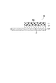
以下、図1を参照して、本発明の第1実施形態の空気極10について説明する。図1は、空気極10の断面図を示す。空気極10は、撥水層1と、触媒層2とを備える。撥水層1は、多孔質である。触媒層2は、撥水層1と接触している。空気極10は、集電体3を更に備えていてもよい。集電体3は、触媒層2の面2bと接触している。触媒層2の面2bは、撥水層1と接触している触媒層2の面2aとは反対側の面である。集電体3上に触媒層2が設けられる。触媒層2上に撥水層1が設けられる。
<First embodiment: air electrode>
Hereinafter, the
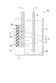
理解を容易にするために、空気極10の詳細な説明に先立ち、第3実施形態の金属空気電池20の概要について説明する。図2は、金属空気電池20の断面図を示す。金属空気電池20は、第1実施形態の空気極10と、金属極5と、電解質4(例えば、電解液)と、ケーシング6とを備える。空気極10は、正極端子T+に接続される。金属極5は、負極端子T-に接続される。ケーシング6は、空気極10と、金属極5と、電解質4とを収容する。ケーシング6は、電解質収容部61を備える。電解質収容部61は、電解質4によって満たされている。ケーシング6の一側面62には、複数個の空気孔63が設けられる。空気孔63を、空気Gが通過する。空気極10の撥水層1は、ケーシング6の一側面62に対向して配置される。空気極10の撥水層1は、空気孔63を介して、空気Gと接触している。空気極10の集電体3は、ケーシング6の電解質収容部61と接触している。空気極10の集電体3は、電解質収容部61を満たす電解質4と接触している。金属極5は電解質収容部61内に配置される。金属極5は、電解質収容部61を満たす電解質4内に配置されている。集電体3を介して金属極5側から触媒層2へ、水を含む電解質4が浸み込む。撥水層1側から触媒層2へ、酸素ガスを含む空気Gが供給される。この結果、空気極10の触媒層2において、電極反応(酸素還元反応)、詳しくは「O2+2H2O+4e-→4OH-」で表される反応が進行する。これにより、金属空気電池20が出力する。このように、空気極10は、酸素ガスを電極活物質とする。以上、図2を参照して、第3実施形態の金属空気電池20の概要について説明した。以下、空気極10について詳細に説明する。
Prior to a detailed description of the
(撥水層)
撥水層1は、金属空気電池20の外側への電解質4が漏れることを防ぐ目的、及び触媒層2への空気Gを送り込む目的で、空気極10に設けられる。撥水層1は、多孔質である。つまり、撥水層1は、多数個の孔を有する。撥水層1及び撥水層1が有する孔の内壁は、撥水性を有する。このため、撥水層1が有する孔内には、水が浸入し難い。しかし、撥水層1が有する孔内を、空気Gは通過することができる。撥水層1は、空気Gを取り込むための多数個の孔を有し、且つ水を含有する電解質4を通し難いといった、相反する特性を備えている。
(Water-repellent layer)
The water-repellent layer 1 is provided on the
第1実施形態の空気極10において、撥水層1の表面における開孔率は、30面積%以上45面積%未満である。撥水層1の表面における開孔率が30面積%未満であると、撥水層1の孔が小さ過ぎる又は少な過ぎる。このため、撥水層1の孔を通じて触媒層2へ空気Gを送り込む能力(以下「空気供給能力」と記載する)が低く、初期から金属空気電池20の出力が低くなる。なお、本明細書において「初期」とは、金属空気電池20の作製直後を意味する。一方、撥水層1の表面における開孔率が45面積%以上であると、撥水層1の孔が大き過ぎる又は多過ぎる。このため、経時的に電解質4が撥水層1の孔内に入り込み、孔内の電解質4によって空気Gの流れが徐々に遮断される。このため、徐々に空気供給能力が低下して、経時的に金属空気電池20の出力が低下する。以上のことから、撥水層1の表面における開孔率を30面積%以上45面積%未満とすることで、金属空気電池20の出力を所望値以上に維持できる。
In the
金属空気電池20の出力を所望値以上に維持するためには、撥水層1の表面における開孔率は、35面積%以上45面積%未満であることが好ましい。また、撥水層1の表面における開孔率は、30面積%、31面積%、32面積%、33面積%、34面積%、35面積%、36面積%、37面積%、38面積%、39面積%、40面積%、41面積%、42面積%、43面積%、及び44面積%から選ばれる2つの値の範囲内であってもよい。
In order to maintain the output of the metal-
撥水層1の表面における数平均孔径は、250nm以下であることが好ましい。撥水層1の表面における開孔率が高い(例えば、30面積%以上45面積%未満である)場合であっても、数平均孔径が250nm以下と撥水層1の孔が微小であることによって、電解質4が撥水層1の孔内に入り込むことを好適に抑制できる。これにより、金属空気電池20の出力を所望値以上に維持できる。
The number average pore size on the surface of the water-repellent layer 1 is preferably 250 nm or less. Even when the porosity on the surface of the water-repellent layer 1 is high (for example, 30 area% or more and less than 45 area%), the number average pore diameter is 250 nm or less and the pores of the water-repellent layer 1 are minute. Thereby, it is possible to preferably suppress the
撥水層1の表面における最大孔径は、500nm以下であることが好ましい。撥水層1の表面における開孔率が高い(例えば、30面積%以上45面積%未満である)場合であっても、最大孔径が500nm以下と撥水層1の孔が微小であることによって、電解質4が撥水層1の孔内に入り込むことを好適に抑制できる。これにより、金属空気電池20の出力を所望値以上に維持できる。
The maximum pore size on the surface of the water-repellent layer 1 is preferably 500 nm or less. Even when the porosity on the surface of the water-repellent layer 1 is high (for example, not less than 30 area% and less than 45 area%), the maximum pore diameter is 500 nm or less and the pores of the water-repellent layer 1 are small. In addition, it is possible to preferably suppress the
撥水層1の表面における最小孔径は、50nm以上であることが好ましい。最小孔径が50nm以上であると、空気供給能力が高まり、初期から金属空気電池20の出力が高くなる。
The minimum pore size on the surface of the water-repellent layer 1 is preferably 50 nm or more. When the minimum pore size is 50 nm or more, the air supply capacity increases, and the output of the metal-
開孔率、数平均孔径、最大孔径、及び最小孔径は、撥水層1の表面(触媒層2と接触している面とは反対側の撥水層1の面)を観察することにより測定される。開孔率、数平均孔径、最大孔径、及び最小孔径の測定方法は、実施例に記載の方法又はその代替法である。 The porosity, the number average pore size, the maximum pore size, and the minimum pore size are measured by observing the surface of the water-repellent layer 1 (the surface of the water-repellent layer 1 opposite to the surface in contact with the catalyst layer 2). Is done. The methods for measuring the porosity, the number average pore size, the maximum pore size, and the minimum pore size are the methods described in the examples or their alternatives.
撥水層1の水との接触角は、100度以上120度以下である。撥水層1の水との接触角が100度未満であると、撥水層1の撥水性が低く過ぎて、経時的に電解質4が撥水層1の孔内に入り込む。このため、孔内の電解質4によって空気Gの流れが徐々に遮断され、徐々に空気供給能力が低下して、経時的に金属空気電池20の出力が低下する。一方、撥水層1の水との接触角が120度より大きいと、撥水層1の撥水性が高過ぎて、撥水層1と触媒層2との密着性が低下する。密着性が低下すると、撥水層1と触媒層2との界面に電解質4が濡れ広がる現象(以下、漏液と記載することがある)が発生する。漏液により、徐々に空気供給能力が低下して、経時的に金属空気電池20の出力が低下する。以上のことから、撥水層1の水との接触角を100度以上120度以下とすることで、金属空気電池20の出力を所望値以上に維持できる。
The contact angle of the water-repellent layer 1 with water is 100 degrees or more and 120 degrees or less. If the contact angle of the water repellent layer 1 with water is less than 100 degrees, the water repellency of the water repellent layer 1 is too low, and the
撥水層1の水との接触角の上限は、120度未満であることが好ましい。撥水層1の水との接触角の下限は、110度以上であることが好ましく、112度以上であることがより好ましく、114度以上であることが更に好ましく、115度以上であることが一層好ましい。また、撥水層1の水との接触角は、100度、102度、110度、112度、114度、115度、118度、及び120度から選ばれる2つの値の範囲内であってもよい。 The upper limit of the contact angle of water-repellent layer 1 with water is preferably less than 120 degrees. The lower limit of the contact angle of the water-repellent layer 1 with water is preferably 110 degrees or more, more preferably 112 degrees or more, further preferably 114 degrees or more, and more preferably 115 degrees or more. More preferred. The contact angle of the water-repellent layer 1 with water is within a range of two values selected from 100 degrees, 102 degrees, 110 degrees, 112 degrees, 114 degrees, 115 degrees, 118 degrees, and 120 degrees. Is also good.
撥水層1の水との接触角は、所望の接触角を有する撥水層形成材料31(図3参照)を適宜選択することにより調整できる。例えば、所望の接触角を有する撥水層形成材料31の市販品を使用することができる。なお、撥水層1の水との接触角は、例えば、後述する撥水層形成材料31の延伸、及び撥水層1と触媒層2との圧着によって、実質的に変化しない。撥水層1の水との接触角の測定方法は、実施例に記載の方法又はその代替法である。
The contact angle of the water-repellent layer 1 with water can be adjusted by appropriately selecting a water-repellent layer forming material 31 having a desired contact angle (see FIG. 3). For example, a commercial product of the water-repellent layer forming material 31 having a desired contact angle can be used. The contact angle of the water-repellent layer 1 with water does not substantially change due to, for example, the stretching of the water-repellent layer forming material 31 described later and the pressure contact between the water-repellent layer 1 and the
撥水層1の水との接触角を所望の範囲内の値に調整しやすいことから、撥水層1は、フッ素樹脂を含有することが好ましく、フッ素樹脂のみを含有することがより好ましい。撥水層1は、1種のフッ素樹脂のみを含有してもよく、2種以上のフッ素樹脂を含有してもよい。撥水層1が含有するフッ素樹脂としては、例えば、ポリテトラフルオロエチレン(以下「PTFE」と記載することがある)、テトラフルオロエチレン−ヘキサフルオロプロピレン共重合体(以下「FEP」と記載することがある)、パーフルオロアルコキシフッ素樹脂(以下「PFA」と記載することがある)、及びポリフッ化ビニリデン(以下「PVDF」と記載することがある)が挙げられる。撥水層1は、PTFE、FEP、PFA、及びPVDFのうちの少なくとも1種(例えば、1種)を含有することが好ましい。 The water-repellent layer 1 preferably contains a fluororesin, and more preferably contains only a fluororesin, since the contact angle of the water-repellent layer 1 with water can be easily adjusted to a value within a desired range. The water-repellent layer 1 may contain only one kind of fluororesin, or may contain two or more kinds of fluororesins. Examples of the fluororesin contained in the water-repellent layer 1 include polytetrafluoroethylene (hereinafter sometimes referred to as “PTFE”) and a tetrafluoroethylene-hexafluoropropylene copolymer (hereinafter referred to as “FEP”). ), Perfluoroalkoxy fluororesin (hereinafter sometimes referred to as “PFA”), and polyvinylidene fluoride (hereinafter sometimes referred to as “PVDF”). The water-repellent layer 1 preferably contains at least one (for example, one) of PTFE, FEP, PFA, and PVDF.
撥水層1は、焼成層であってもよく、未焼成層であってもよい。未焼成層は、撥水層形成材料31の混練物を焼成することなく、自然乾燥させることにより得られる。撥水層1の水との接触角を所望の範囲内の値に維持するためには、撥水層1は、未焼成層であることが好ましい。撥水層1は、1層構造を有していてもよく、2層又は3層以上の多層構造を有していてもよい。 The water-repellent layer 1 may be a fired layer or an unfired layer. The unfired layer is obtained by naturally drying the kneaded material of the water-repellent layer forming material 31 without firing. In order to maintain the contact angle of the water-repellent layer 1 with water within a desired range, the water-repellent layer 1 is preferably an unfired layer. The water-repellent layer 1 may have a single-layer structure, or may have a multilayer structure of two or three or more layers.
撥水層1の厚さは、100μm以上250μm以下であることが好ましい。撥水層1の厚さが100μm以上であると、撥水層1に適度な強度を付与できる。撥水層1の厚さが250μm以下であると、触媒層2への空気Gの供給が容易となる。
The thickness of the water-repellent layer 1 is preferably 100 μm or more and 250 μm or less. When the thickness of the water-repellent layer 1 is 100 μm or more, the water-repellent layer 1 can have an appropriate strength. When the thickness of the water-repellent layer 1 is 250 μm or less, the supply of the air G to the
(触媒層)
触媒層2は、多孔質であることが好ましい。触媒層2の厚さは、例えば、100μm以上2mm以下であることが好ましく、500μm以上1mm以下であることがより好ましい。触媒層2は、例えば、結着剤と、触媒粒子と、導電剤とを含有する。
(Catalyst layer)
The
結着剤は、触媒層2の形状を保つ目的で、触媒層2に含有される。結着剤としては、例えば、フッ素樹脂が挙げられる。フッ素樹脂は耐アルカリ性を有するため、フッ素樹脂がアルカリ性の電解質4により腐食することを抑制できる。フッ素樹脂としては、PTFEが好ましい。PTFEは、繊維状に発達しながら触媒粒子を結着することができる。また、PTFEは、撥水性及び耐熱性に優れる。
The binder is contained in the
触媒粒子は、酸素還元反応に対する触媒活性を有する。触媒粒子の表面において、酸素還元反応が進行する。触媒粒子の材料としては、例えば、金属酸化物及び銀が挙げられる。金属酸化物としては、例えば、酸化マンガン(具体的には、MnO2、及びMn3O4等)及びペロブスカイト型金属酸化物が挙げられる。触媒粒子の表面は、導電剤により覆われていてもよい。また、触媒粒子の表面が、導電剤により構成される多孔質層で覆われていてもよい。触媒粒子の表面が導電剤により覆われていることで、酸素還元反応が進行する触媒粒子の表面に、速やかに電子を供給することができる。触媒粒子の体積中位径D50は、5μm以上100μm以下であることが好ましく、5μm以上50μm以下であることがより好ましい。触媒粒子の体積中位径D50がこのような範囲内であると、触媒粒子の表面を導電剤で容易に覆うことができる。 The catalyst particles have catalytic activity for the oxygen reduction reaction. The oxygen reduction reaction proceeds on the surface of the catalyst particles. Examples of the material of the catalyst particles include metal oxides and silver. Examples of the metal oxide include manganese oxide (specifically, MnO 2 and Mn 3 O 4 and the like) and perovskite-type metal oxide. The surface of the catalyst particles may be covered with a conductive agent. Further, the surface of the catalyst particles may be covered with a porous layer made of a conductive agent. Since the surfaces of the catalyst particles are covered with the conductive agent, electrons can be quickly supplied to the surfaces of the catalyst particles where the oxygen reduction reaction proceeds. The volume median diameter D 50 of the catalyst particles is preferably from 5 μm to 100 μm, more preferably from 5 μm to 50 μm. If the volume median diameter D 50 of the catalyst particles is within such a range, it is possible to easily cover the surface of the catalyst particles in the conductive agent.
導電剤は、集電体3と触媒粒子の表面とを電気的に接続し、酸素還元反応に必要な電子を触媒粒子の表面に供給する。導電剤は、例えば、導電性を有する炭素粒子である。導電剤の材料としては、例えば、カーボンブラック、カーボンファイバー、カーボンナノチューブ、活性炭、及びグラファイトが挙げられる。導電剤の体積中位径D50は、10nm以上100nm以下であることが好ましく、10nm以上50nm以下であることがより好ましい。導電剤の体積中位径D50がこのような範囲内であると、触媒層2内で、導電剤が効率的に導電経路を形成することができる。
The conductive agent electrically connects the
(集電体)
集電体3は、気体である酸素ガスと、液体である水と、固体である触媒粒子との三相界面(例えば、触媒粒子の表面)に、電子を供給する。集電体3は、水を通過させる孔を有している。集電体3は、多孔質である。集電体3の厚さは、100μm以上600μm以下であることが好ましい。
(Current collector)
The
集電体3の材質としては、例えば、ニッケル、銀、金、白金、及びステンレス鋼が挙げられる。また、集電体3の材質は、ニッケルめっき処理された金属であってもよい。ニッケルめっき処理された金属としては、例えば、ニッケルメッキされた鉄、及びニッケルメッキされたステンレス鋼が挙げられる。集電体3の材質は、ニッケル又はニッケルめっき処理された金属であることが好ましい。このような材質の集電体3は耐アルカリ性を有するため、集電体3がアルカリ性の電解質4により腐食することを抑制できる。
Examples of the material of the
集電体3の形状は特に限定されず、集電体3は、例えば、平板状構造、又は網状構造を有していてもよい。集電体3を介して触媒層2と撥水層1とを強く密着させるためには、集電体3が網状構造を有していることが好ましい。
The shape of the
網状構造を有する集電体3としては、例えば、金属メッシュ、エキスパンドメタル、及びパンチングメタルが挙げられる。金属メッシュとしては、例えば、平織、綾織、平畳織、及び綾畳織の金属メッシュが挙げられる。集電体3は、平織の金属メッシュを含むことが好ましく、10メッシュ以上30メッシュ以下の平織の金属メッシュを含むことがより好ましい。
Examples of the
以上、第1実施形態の空気極10について説明した。第1実施形態の空気極10によれば、金属空気電池20の出力を所望値以上に維持できる。また、電界紡糸のような工程が不要となるため、第1実施形態の空気極10によれば、製造工程の簡略化及び製造コストの低減を図りつつ、金属空気電池20の出力を所望値以上に維持できる。
The
<第2実施形態:空気極の製造方法>
第2実施形態の空気極10の製造方法は、第1実施形態の空気極10を製造するための方法である。以下、空気極10の製造方法の一例を説明する。空気極10の製造方法は、撥水層形成工程と、圧着工程とを少なくとも含む。空気極10の製造方法は、必要に応じて、触媒層形成工程を更に含んでいてもよい。
<Second embodiment: manufacturing method of air electrode>
The method for manufacturing the
(触媒層形成工程)
触媒層形成工程において、触媒粒子の粉末と、導電剤と、結着剤と、分散媒とを混練して混練物を形成する。次いで、混練物を圧延して、触媒層2を形成する。触媒層2は、例えば、シート状である。なお、触媒層2として市販品を使用する場合には、触媒層形成工程を省略してもよい。
(Catalyst layer forming step)
In the catalyst layer forming step, the powder of the catalyst particles, the conductive agent, the binder, and the dispersion medium are kneaded to form a kneaded product. Next, the kneaded material is rolled to form the
(撥水層形成工程)
撥水層形成工程において、撥水層形成材料31を延伸して、撥水層1を形成する。無孔層である撥水層形成材料31が引き伸ばされることによって、撥水層1が形成されるとともに、撥水層1に多数個の孔が形成される。このようにして、延伸により、撥水層1の表面における開孔率が40面積%以上となるように、撥水層1に多数個の孔が形成される。撥水層形成材料31としては、既に述べた撥水層1に含有されるフッ素樹脂が挙げられる。延伸は、1軸延伸であってもよく、2軸延伸であってもよい。1軸延伸は、撥水層1の幅方向又は長さ方向における延伸である。2軸延伸は、撥水層1の幅方向及び長さ方向の両方向における延伸である。延伸は、例えば、延伸機を用いて行われる。
(Water-repellent layer forming step)
In the water-repellent layer forming step, the water-repellent layer forming material 31 is stretched to form the water-repellent layer 1. By stretching the water-repellent layer forming material 31 which is a non-porous layer, the water-repellent layer 1 is formed, and a large number of holes are formed in the water-repellent layer 1. In this way, a large number of holes are formed in the water-repellent layer 1 by stretching such that the porosity on the surface of the water-repellent layer 1 is 40 area% or more. Examples of the water-repellent layer forming material 31 include the above-mentioned fluororesin contained in the water-repellent layer 1. The stretching may be uniaxial stretching or biaxial stretching. The uniaxial stretching is stretching in the width direction or the length direction of the water-repellent layer 1. Biaxial stretching is stretching in both the width direction and the length direction of the water-repellent layer 1. The stretching is performed using, for example, a stretching machine.
図3を参照しながら、撥水層形成材料31が1軸延伸される場合を例に挙げて、延伸方法について説明する。図3は、延伸機の延伸ユニット30の上面を示し、この延伸機は空気極10の製造方法の撥水層形成工程に用いられる。延伸機は、延伸ユニット30を備える。延伸ユニット30には、撥水層形成材料31がセットされる。撥水層形成材料31は、例えば、シート状である。延伸ユニット30は、第1クリップ32と、第2クリップ33と、第1クリップ搬送路34と、第2クリップ搬送路35とを備える。撥水層形成材料31は、搬送方向Dsに沿って搬送される。第1クリップ32は、撥水層形成材料31の一端を挟む。第2クリップ33は、撥水層形成材料31の他端を挟む。第1クリップ32、及び第2クリップ33は、各々、第1クリップ32及び第2クリップ33を移動させるための駆動装置(不図示)に接続している。第1クリップ32は、第1クリップ搬送路34に沿って移動する。第2クリップ33は、第2クリップ搬送路35に沿って移動する。
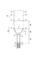
The stretching method will be described with reference to FIG. 3 by taking as an example a case where the water-repellent layer forming material 31 is uniaxially stretched. FIG. 3 shows the upper surface of the stretching
延伸ユニット30には、撥水層形成材料31の搬送方向Dsの上流側から、第1領域301と、第2領域302(延伸領域)と、第3領域303(熱処理領域)とが、記載された順に配置されている。また、延伸ユニット30には、第1位置P1〜第10位置P10が設定される。第1位置P1は、第1クリップ搬送路34上で、且つ撥水層形成材料31の搬送方向Dsにおける第1領域301の上流端に位置する。第2位置P2は、第2クリップ搬送路35上で、且つ撥水層形成材料31の搬送方向Dsにおける第1領域301の上流端に位置する。第3位置P3は、第1クリップ搬送路34上で、且つ撥水層形成材料31の搬送方向Dsにおける第1領域301の下流端に位置する。第4位置P4は、第2クリップ搬送路35上で、且つ撥水層形成材料31の搬送方向Dsにおける第1領域301の下流端に位置する。第5位置P5は、第1クリップ搬送路34上で、且つ撥水層形成材料31の搬送方向Dsにおける第2領域302の下流端に位置する。第6位置P6は、第2クリップ搬送路35上で、且つ撥水層形成材料31の搬送方向Dsにおける第2領域302の下流端に位置する。第7位置P7は、第1クリップ搬送路34上で、且つ撥水層形成材料31の搬送方向Dsにおける第3領域303の下流端に位置する。第8位置P8は、第2クリップ搬送路35上で、且つ撥水層形成材料31の搬送方向Dsにおける第3領域303の下流端に位置する。第9位置P9は、第1クリップ搬送路34上で、且つ撥水層形成材料31の搬送方向Dsにおける第3領域303よりも下流に位置する。第10位置P10は、第2クリップ搬送路35上で、且つ撥水層形成材料31の搬送方向Dsにおける第3領域303よりも下流に位置する。
The stretching
第1領域301において、第1クリップ搬送路34と第2クリップ搬送路35とは、互いに平行になるように対向して配置される。また、第1領域301において、第1クリップ搬送路34と第2クリップ搬送路35とは、各々、搬送方向Dsに対して平行に配置される。第1位置P1と第2位置P2との間の距離L1は、第3位置P3と第4位置P4との間の距離L2と同じである。延伸ユニット30の第2領域302(延伸領域)において、第1クリップ搬送路34と第2クリップ搬送路35とのレール間距離が徐々に大きくなるように、第1クリップ搬送路34と第2クリップ搬送路35とが対向して配置される。第5位置P5と第6位置P6との間の距離L3は、第3位置P3と第4位置P4との間の距離L2よりも長い。延伸ユニット30の第3領域303(熱処理領域)において、第1クリップ搬送路34と第2クリップ搬送路35とは、互いに平行になるように対向して配置される。また、第3領域303において、第1クリップ搬送路34と第2クリップ搬送路35とは、各々、搬送方向Dsに対して平行に配置される。第5位置P5と第6位置P6との間の距離L3は、第7位置P7と第8位置P8との間の距離L4と同じである。
In the
延伸は、例えば、次の手順で行われる。第1位置P1において、搬送方向Dsに沿って搬送されてきた撥水層形成材料31の一端を、第1クリップ32が挟む。第2位置P2において、搬送方向Dsに沿って搬送された撥水層形成材料31の他端を、第2クリップ33が挟む。撥水層形成材料31が第1クリップ32及び第2クリップ33に挟まれた状態で、第1位置P1から第3位置P3まで第1クリップ搬送路34に沿って第1クリップ32が移動し、第2位置P2から第4位置P4まで第2クリップ搬送路35に沿って第2クリップ33が移動する。次いで、撥水層形成材料31が第1クリップ32及び第2クリップ33に挟まれた状態で、第3位置P3から第5位置P5まで第1クリップ搬送路34に沿って第1クリップ32が移動し、第4位置P4から第6位置P6まで第2クリップ搬送路35に沿って第2クリップ33が移動する。第2領域302(延伸領域)において、第1クリップ搬送路34と第2クリップ搬送路35とのレール間距離が徐々に大きくなるにつれて、搬送方向Dsに対して垂直な方向(幅方向)に、撥水層形成材料31が徐々に延伸される。延伸により、撥水層1が得られる。
Stretching is performed, for example, in the following procedure. In the first position P 1, one end of the water-repellent layer forming material 31 which has been conveyed along the conveying direction D s, the first clip 32 is sandwiched. In the second position P 2, the other end of the conveying direction D s repellent layer forming material 31 which is conveyed along the
次いで、撥水層1は、必要に応じて、第3領域303(熱処理領域)において、熱処理されてもよい。撥水層1が熱処理される場合、撥水層1が第1クリップ32及び第2クリップ33に挟まれた状態で熱処理されながら、第5位置P5から第7位置P7まで第1クリップ搬送路34に沿って第1クリップ32が移動し、第6位置P6から第8位置P8まで第2クリップ搬送路35に沿って第2クリップ33が移動する。
Next, the water-repellent layer 1 may be heat-treated as necessary in the third region 303 (heat-treated region). If the water-repellent layer 1 is heat treated, while being heat-treated in a state where the water-repellent layer 1 is sandwiched between the first clip 32 and
但し、撥水層1に、熱処理を行わなくてもよい。撥水層1が熱処理されない場合、撥水層1が第1クリップ32及び第2クリップ33に挟まれた状態で、第5位置P5から第7位置P7まで第1クリップ搬送路34に沿って第1クリップ32が移動し、第6位置P6から第8位置P8まで第2クリップ搬送路35に沿って第2クリップ33が移動する。
However, heat treatment does not have to be performed on the water-repellent layer 1. If the water-repellent layer 1 is not heat treated, with the water-repellent layer 1 is sandwiched between the first clip 32 and
次いで、撥水層1が第1クリップ32及び第2クリップ33に挟まれた状態で、第7位置P7から第9位置P9まで第1クリップ搬送路34に沿って第1クリップ32が移動し、第8位置P8から第10位置P10まで第2クリップ搬送路35に沿って第2クリップ33が移動する。次いで、第9位置P9で第1クリップ32が撥水層1を放し、第10位置P10で第2クリップ33が撥水層1を放す。
Then, in a state where the water-repellent layer 1 is sandwiched between the first clip 32 and
撥水層1の表面における開孔率は、第3位置P3と第4位置P4との間の距離L2、第5位置P5と第6位置P6との間の距離L3、搬送方向Dsにおける第2領域302の長さL5、及び撥水層形成材料31の搬送速度のうちの少なくとも1つを変更することにより調整できる。第3位置P3と第4位置P4との間の距離L2が小さくなる程、撥水層1の表面における開孔率は高くなる。第5位置P5と第6位置P6との間の距離L3が大きくなる程、撥水層1の表面における開孔率は高くなる。搬送方向Dsにおける第2領域302の長さL5が短くなる程、撥水層1の表面における開孔率は高くなる。撥水層形成材料31の搬送速度が速くなる程、撥水層1の表面における開孔率は高くなる。
The porosity on the surface of the water-repellent layer 1 includes a distance L 2 between the third position P 3 and the fourth position P 4 , a distance L 3 between the fifth position P 5 and the sixth position P 6 , It can be adjusted by changing at least one of the length L 5 of the
第3位置P3と第4位置P4との間の距離L2は、50mm以上500mm以下であることが好ましい。第5位置P5と第6位置P6との間の距離L3は、100mm以上1000mm以下であることが好ましい。搬送方向Dsにおける第2領域302の長さL5は、0.5m以上3.0m以下であることが好ましく、0.5m以上1.8m以下であることがより好ましい。撥水層形成材料31の搬送速度は、1m/分以上5m/分以下であることが好ましい。
A third position P 3 distance L 2 between the fourth position P 4 is preferably at least 50mm 500mm or less. A fifth position P 5 distance L 3 between the sixth position P 6 is preferably 100mm or more 1000mm or less. The length L 5 in the transport direction Ds in the
なお、延伸前に撥水層形成材料31を延伸させ易い形状に加工してもよい。例えば、撥水層形成材料31を混練して混練物を得、混練物を圧延してシート状の圧延物を得、シート状の圧延物を延伸に用いてもよい。 Note that the water-repellent layer forming material 31 may be processed into a shape that can be easily stretched before stretching. For example, the water-repellent layer forming material 31 may be kneaded to obtain a kneaded product, and the kneaded product may be rolled to obtain a sheet-shaped rolled product, and the sheet-shaped rolled product may be used for stretching.
(圧着工程)
圧着工程において、撥水層1と、触媒層2と、任意の集電体3とを圧着する。撥水層1と触媒層2と任意の集電体3とを圧着することにより、空気極10が得られる。まず、集電体3と、集電体3上に配置される触媒層2と、触媒層2上に配置される撥水層1とを備える積層体を準備する。積層体の表面に対して垂直な方向に、圧着のための圧力(以下「プレス圧」と記載することがある)を付与する。このようにして、積層体の表面に位置する撥水層1に圧力を付与することにより、撥水層1の表面における開孔率を低下させる。つまり、撥水層1に圧力を付与することにより、多孔質層である撥水層1の孔を適度につぶして、撥水層1の表面における開孔率を低下させる。開孔率の低下によって、撥水層1の表面における開孔率が30面積%以上45面積%未満に調整される。
(Crimping process)
In the pressure bonding step, the water repellent layer 1, the
撥水層1の表面における開孔率の低下率Aは、20.0%以上であることが好ましい。撥水層1の表面における開孔率の低下率Aは、下記式(1)から算出される。式(1)中、A1は圧着工程の前の撥水層1の表面における開孔率を表す。A2は圧着工程の後の撥水層1の表面における開孔率を表す。
A=100×(A1−A2)/A1・・・(1)
The rate of decrease A of the porosity on the surface of the water-repellent layer 1 is preferably 20.0% or more. The decrease rate A of the porosity on the surface of the water-repellent layer 1 is calculated from the following equation (1). In the formula (1), A 1 represents the porosity on the surface of the water-repellent layer 1 before the pressure bonding step. A 2 represents a rate of porosity of the surface of the water-repellent layer 1 after the crimping process.
A = 100 × (A 1 −A 2 ) / A 1 (1)
プレス圧が高い程、開孔率の低下率Aは高くなる。開孔率の低下率Aは、プレス圧がどの程度であるかを示す指標となる。開孔率の低下率Aが20.0%以上であると、プレス圧が高くなり、撥水層1と触媒層2との接着力が高まり、密着性が向上する。これにより、漏液の発生による空気供給能力の低下を好適に抑制でき、金属空気電池20の出力を所望値以上に好適に維持できる。
The higher the pressing pressure, the higher the rate of decrease A in the opening ratio. The decrease rate A of the opening ratio is an index indicating the pressing pressure. When the decrease rate A of the porosity is 20.0% or more, the pressing pressure is increased, the adhesive force between the water-repellent layer 1 and the
撥水層1と触媒層2との接着力を高めて、金属空気電池20の出力の低下を抑制するためには、開孔率の低下率Aは、22.0%以上であることが好ましく、24.0%以上であることがより好ましく、25.0%以上であることが更に好ましく、30.0%以上であることが一層好ましく、40.0%以上であることが特に好ましい。開孔率の低下率Aの上限は特に限定されないが、例えば、50.0%未満である。開孔率の低下率Aが50.0%未満であると、撥水層1の孔が適度に残るため、空気供給能力を好適に維持できる。
In order to increase the adhesive force between the water-repellent layer 1 and the
撥水層1と触媒層2との接着力を高めつつ、圧着工程後の撥水層1の表面における開孔率を所望の範囲内に調整するためには、圧着工程前の撥水層1の表面における開孔率は、40面積%以上であることが好ましく、40面積%以上80面積%以下であることがより好ましく、40面積%以上60面積%以下であることが更に好ましい。圧着工程後の撥水層1の表面における開孔率は、第1実施形態で述べた撥水層1の表面における開孔率に相当する。
In order to adjust the porosity on the surface of the water-repellent layer 1 after the pressure bonding step to a desired range while increasing the adhesive force between the water-repellent layer 1 and the
開孔率の低下率Aを所望の範囲に調整し易いことから、プレス圧は、1.80kN/cm2以上3.00kN/cm2以下であることが好ましく、1.85kN/cm2以上2.80kN/cm2以下であることがより好ましい。プレス時間は、0.5分以上10分以下であることが好ましい。以上、第2実施形態の空気極10の製造方法について説明した。
Since easily adjust the reduction rate A of the porosity in the desired range, the pressing pressure is preferably at 1.80kN / cm 2 or more 3.00kN / cm 2 or less, 1.85kN / cm 2 or more 2 More preferably, it is not more than .80 kN / cm 2 . The pressing time is preferably 0.5 minutes or more and 10 minutes or less. The method for manufacturing the
<第3実施形態:金属空気電池>
次に、第3実施形態の金属空気電池20を説明する。金属空気電池20の概要は、図2を参照して、既に述べたとおりである。金属空気電池20は、第1実施形態の空気極10と、金属極5と、電解質4とを少なくとも備える。金属空気電池20は、金属極5を負極(アノード)とし、空気極10を正極(カソード)とする。金属空気電池20は、例えば、亜鉛空気電池、リチウム空気電池、ナトリウム空気電池、カルシウム空気電池、マグネシウム空気電池、アルミニウム空気電池、又は鉄空気電池である。金属極5の材料としては、例えば、亜鉛、リチウム、ナトリウム、カルシウム、マグネシウム、アルミニウム、及び鉄が挙げられる。電解質4としては、電解液が好ましく、水酸化カリウム水溶液がより好ましい。金属空気電池20は、公知の方法により組み立てることができる。以上、第3実施形態の金属空気電池20について説明した。
<Third embodiment: metal-air battery>
Next, a metal-
以下、実施例を用いて本発明を更に具体的に説明するが、本発明は実施例の範囲に何ら限定されない。 Hereinafter, the present invention will be described more specifically with reference to examples, but the present invention is not limited to the scope of the examples.
空気極(A−1)〜(A−9)及び(B−1)〜(B−14)の作製方法、測定方法、評価方法、及び評価結果について、説明する。 The production methods, measurement methods, evaluation methods, and evaluation results of the air electrodes (A-1) to (A-9) and (B-1) to (B-14) will be described.
[作製方法]
<空気極(A−1)の作製>
(触媒層形成工程)
触媒としての二酸化マンガン(中央電気工業株式会社製「CMD−K200」)1.0重量部と、導電剤としてのカーボンブラック1.5重量部とを、ボールミルを用いて、一晩混合した。ボールミルには、直径4mmのジルコニアボールを使用した。加圧ニーダーの容器に、得られた混合物(詳しくは、二酸化マンガン及びカーボンブラックの混合物)と、結着剤としてのPTFE(ダイキン工業株式会社製「ポリフロン PTFE D−210C」、PTFE分散液、分散媒:水、固形分濃度:60wt%)と、水とを加えた。PTFE分散液の添加量は、容器内の全固形分の重量に対するPTFEの含有率が25wt%となるような量であった。水の添加量は、容器内の全固形分の濃度が50wt%となるような量であった。加圧ニーダーを用いて、容器の内容物を混練して、混練物を得た。ロール圧延機を用いて、混練物をシート状に成形して、乾燥させた。これにより、触媒層を得た。
[Production method]
<Preparation of air electrode (A-1)>
(Catalyst layer forming step)
1.0 part by weight of manganese dioxide as a catalyst ("CMD-K200" manufactured by Chuo Electric Co., Ltd.) and 1.5 parts by weight of carbon black as a conductive agent were mixed overnight using a ball mill. For the ball mill, zirconia balls having a diameter of 4 mm were used. In a container of a pressure kneader, the obtained mixture (specifically, a mixture of manganese dioxide and carbon black), PTFE as a binder (“Polyflon PTFE D-210C” manufactured by Daikin Industries, Ltd.), PTFE dispersion, dispersion (Medium: water, solid content concentration: 60 wt%) and water. The amount of the PTFE dispersion added was such that the content of PTFE with respect to the weight of the total solid content in the container was 25 wt%. The amount of water added was such that the concentration of the total solid content in the container became 50 wt%. The contents of the container were kneaded using a pressure kneader to obtain a kneaded material. The kneaded material was formed into a sheet using a roll rolling mill, and dried. Thus, a catalyst layer was obtained.
(撥水層形成工程)
図3を再び参照して、撥水層1の作製について説明する。PTFE粉末(ダイキン工業株式会社製「ポリフロンPTFE F−104」)100重量部とエタノール100重量部とを混練して、混練物を得た。ロール圧延機(株式会社サンクメタル製「メカ式加圧1トン精密ロールプレス」)を用いて、混練物を圧延して、シート状の圧延物を得た。このシート状の圧延物を撥水層形成材料31とした。シート状の圧延物は、無孔膜であった。続いて、延伸機(ブルックナー社製)を用いて、シート状の圧延物を延伸(より具体的には、1軸延伸)した。延伸機の延伸ユニット30の第2領域302(延伸領域)において、撥水層形成材料31の搬送方向Dsに対して垂直な方向に、シート状の圧延物が延伸された。延伸条件は、入口幅(距離L2)が300mmであり、出口幅(距離L3)が800mmであり、延伸領域の長さ(第2領域302の長さL5)が1.0mであり、シート搬送速度が3m/分であった。延伸により、シート状の延伸物が得られた。このようにして、多孔膜である撥水層1を得た。なお、撥水層形成工程は常温にて行い、第3領域303(熱処理領域)における熱処理は行わなかった。以上、図3を参照して、撥水層1の作製について説明した。
(Water-repellent layer forming step)
With reference to FIG. 3 again, the production of the water-repellent layer 1 will be described. 100 parts by weight of PTFE powder (“Polyflon PTFE F-104” manufactured by Daikin Industries, Ltd.) and 100 parts by weight of ethanol were kneaded to obtain a kneaded product. The kneaded material was rolled using a roll rolling machine (“Mechanical pressure 1-ton precision roll press” manufactured by Sank Metal Co., Ltd.) to obtain a sheet-like rolled product. This sheet-shaped roll was used as a water-repellent layer forming material 31. The rolled sheet was a non-porous film. Subsequently, the sheet-shaped rolled product was stretched (more specifically, uniaxially stretched) using a stretching machine (manufactured by Bruckner). In the second region 302 (stretching region) of the stretching
(圧着工程)
集電体として、ニッケルメッシュ(20メッシュ)を使用した。集電体の上に、作製した触媒層を配置した。触媒層の上に、作製した撥水層を配置した。次いで、圧着工程を行った。詳しくは、撥水層の表面に対して垂直方向に、圧力を付与(プレス)しながら、撥水層と触媒層と集電体とを一体化して、空気極(A−1)を得た。圧力を付与した際に、撥水層と触媒層とが圧着された。プレスの条件は、プレス圧が表1に示す通りであり、プレス時間が2分間であり、プレス温度が25℃であった。
(Crimping process)
Nickel mesh (20 mesh) was used as a current collector. The prepared catalyst layer was arranged on the current collector. The produced water repellent layer was disposed on the catalyst layer. Next, a pressure bonding step was performed. Specifically, while applying pressure (pressing) in a direction perpendicular to the surface of the water-repellent layer, the water-repellent layer, the catalyst layer, and the current collector were integrated to obtain an air electrode (A-1). . When pressure was applied, the water repellent layer and the catalyst layer were pressed. The pressing conditions were as follows: the pressing pressure was as shown in Table 1, the pressing time was 2 minutes, and the pressing temperature was 25 ° C.
<空気極(A−2)〜(A−9)及び(B−10)〜(B−14)の作製>
表1に示す撥水層形成材料を使用したこと、撥水層形成工程の延伸における延伸領域の長さを表1に示す長さに設定したこと、及び圧着工程におけるプレス圧を表1に示すプレス圧に設定したこと以外は、空気極(A−1)の作製と同じ方法で、空気極(A−2)〜(A−9)及び(B−10)〜(B−14)の各々を作製した。
<Production of Air Electrodes (A-2) to (A-9) and (B-10) to (B-14)>
Table 1 shows that the water-repellent layer forming material shown in Table 1 was used, the length of the stretched region in the stretching in the water-repellent layer forming step was set to the length shown in Table 1, and the pressing pressure in the pressure bonding step was shown in Table 1. Except that the pressing pressure was set, each of the air electrodes (A-2) to (A-9) and (B-10) to (B-14) was produced in the same manner as in the production of the air electrode (A-1). Was prepared.
<空気極(B−1)〜(B−9)の作製>
表1に示す撥水層形成材料を使用したこと、撥水層形成工程を行うことなく表1に示す撥水層形成材料をそのまま撥水層として使用したこと、及び圧着工程におけるプレス圧を表1に示すプレス圧に設定したこと以外は、空気極(A−1)の作製と同じ方法で、空気極(B−1)〜(B−9)の各々を作製した。
<Production of Air Electrodes (B-1) to (B-9)>
Table 1 shows that the water-repellent layer forming material shown in Table 1 was used, the water-repellent layer forming material shown in Table 1 was directly used as the water-repellent layer without performing the water-repellent layer forming step, and the press pressure in the pressure bonding step was shown. Each of the air electrodes (B-1) to (B-9) was produced in the same manner as in the production of the air electrode (A-1) except that the press pressure was set to 1.
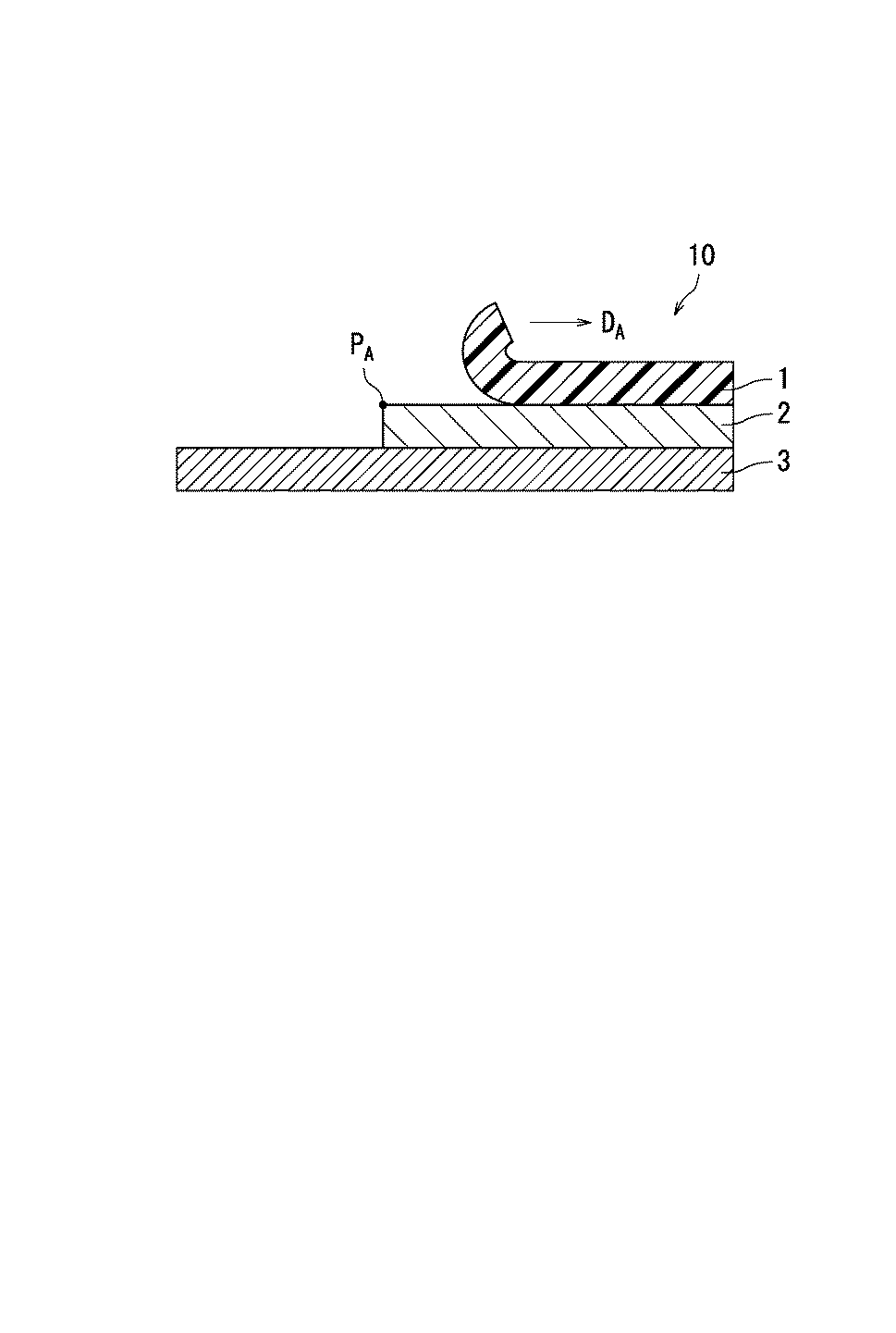
表1中の「A」は、上記<空気極(A−1)の作製>の撥水層形成工程で作製した撥水層形成材料31(無孔膜)を示す。なお、PTFE粉末のロットにより、4種類の接触角(具体的には、114度、115度、116度、及び118度)を有する撥水層形成材料31の各々が得られた。「B」は、ダイキン工業株式会社製「ネオフロンPFAフィルム AF−0100」を示す。「C」は、ダイキン工業株式会社製「ネオフロンFEPフィルム NF−0100」を示す。「D」は、PROFESSIONAL PLASTICS社製「PVDFフィルム」を示す。「E」は、住友電工ファインポリマー株式会社製「ポアフロン(登録商標)FP−022−60」を示す。「F」は、住友電工ファインポリマー株式会社製「ポアフロン HP−020−30」を示す。「G」は、住友電工ファインポリマー株式会社製「ポアフロン WP−020−80」を示す。「H」は、東レ株式会社製「トレファン(登録商標)BO」を示す。「I」は、日東電工株式会社製「サンマップ(登録商標)LC」を示す。「J」は、東レ株式会社製「ルミラー(登録商標)」を示す。表1中の「B」〜「D」で示す撥水層形成材料に対しては、撥水層形成工程において、混練及びロール圧延機による圧延を行わず、延伸機による延伸のみを行った。表1中の「−」は、撥水層形成工程を行わず、「撥水層形成材料」欄に記載の市販品を、そのまま撥水層として使用したことを示す。 “A” in Table 1 indicates the water-repellent layer forming material 31 (non-porous film) manufactured in the water-repellent layer forming step of the above <Preparation of air electrode (A-1)>. Each lot of the PTFE powder obtained each of the water-repellent layer forming materials 31 having four types of contact angles (specifically, 114 degrees, 115 degrees, 116 degrees, and 118 degrees). "B" indicates "Neoflon PFA film AF-0100" manufactured by Daikin Industries, Ltd. "C" indicates "NEOFLON FEP film NF-0100" manufactured by Daikin Industries, Ltd. “D” indicates “PVDF film” manufactured by PROFESSIONAL PLASTICS. “E” indicates “Pouflon (registered trademark) FP-022-60” manufactured by Sumitomo Electric Fine Polymer Co., Ltd. “F” indicates “Pouflon HP-020-30” manufactured by Sumitomo Electric Fine Polymer Co., Ltd. “G” indicates “Pouflon WP-020-80” manufactured by Sumitomo Electric Fine Polymer Co., Ltd. “H” indicates “Trefane (registered trademark) BO” manufactured by Toray Industries, Inc. “I” indicates “Sunmap (registered trademark) LC” manufactured by Nitto Denko Corporation. "J" indicates "Lumirror (registered trademark)" manufactured by Toray Industries, Inc. For the water-repellent layer forming materials indicated by "B" to "D" in Table 1, in the water-repellent layer forming step, kneading and rolling by a roll rolling machine were not performed, but only stretching by a stretching machine was performed. "-" In Table 1 indicates that the water-repellent layer was not subjected to the step of forming a water-repellent layer, and the commercial product described in the column of "Material for forming a water-repellent layer" was used as it was as a water-repellent layer.
[測定方法]
<撥水層の水との接触角の測定>
動的接触角計(FTA社製「FTA125」)を用いて、上記撥水層の作製で得られた撥水層の表面の水との接触角を測定した。水との接触角を、表2及び表3に示す。
[Measuring method]
<Measurement of contact angle of water-repellent layer with water>
Using a dynamic contact angle meter (“FTA125” manufactured by FTA), the contact angle of water on the surface of the water-repellent layer obtained in the preparation of the water-repellent layer was measured. Tables 2 and 3 show the contact angles with water.
<圧着工程前の撥水層の開孔率の測定>
走査型電子顕微鏡(SEM、株式会社日立ハイテクノロジーズ製「電界放出形走査電子顕微鏡 S−4800」)を用いて、1万倍の倍率で、圧着工程前の撥水層の表面を観察し、SEM画像を得た。SEM画像に画像処理を行うことにより、1視野中に観察される多数個の孔の各々の面積を算出した。式「開孔率=100×多数個の孔の面積の合計/1視野の面積」から、圧着工程前の撥水層の表面における開孔率A1(単位:面積%)を算出した。開孔率A1を、表3に示す。
<Measurement of porosity of water-repellent layer before pressure bonding step>
Using a scanning electron microscope (SEM, "Field emission scanning electron microscope S-4800" manufactured by Hitachi High-Technologies Corporation), the surface of the water-repellent layer before the crimping step was observed at a magnification of 10,000 times, and SEM Image obtained. By performing image processing on the SEM image, the area of each of a large number of holes observed in one visual field was calculated. The porosity A 1 (unit: area%) on the surface of the water-repellent layer before the pressure bonding step was calculated from the formula “porosity = 100 × total area of many holes / 1 area of one visual field”. The opening ratio A 1, shown in Table 3.
<圧着工程後の撥水層の開孔率の測定>
走査型電子顕微鏡(SEM、株式会社日立ハイテクノロジーズ製「電界放出形走査電子顕微鏡 S−4800」)を用いて、1万倍の倍率で、圧着工程後の撥水層の表面(触媒層と接触している面と反対側の面)を観察し、SEM画像を得た。SEM画像に画像処理を行うことにより、1視野中に観察される多数個の孔の各々の面積を算出した。式「開孔率=100×多数個の孔の面積の合計/1視野の面積」から、圧着工程後の撥水層の表面における開孔率A2(単位:面積%)を算出した。圧着工程後の撥水層の表面における開孔率A2を、表2及び表3に示す。
<Measurement of porosity of water-repellent layer after pressure bonding step>
Surface of the water-repellent layer after contact bonding with a scanning electron microscope (SEM, Hitachi High-Technologies Corporation, “Field emission scanning electron microscope S-4800”) at a magnification of 10,000 times (contact with the catalyst layer) And the SEM image was obtained. By performing image processing on the SEM image, the area of each of a large number of holes observed in one visual field was calculated. The porosity A 2 (unit: area%) on the surface of the water-repellent layer after the pressure bonding step was calculated from the formula “porosity = 100 × total area of many holes / 1 area of one visual field”. The porosity A 2 at the surface of the water-repellent layer after the pressure bonding step, shown in Table 2 and Table 3.
また、測定した圧着工程前の撥水層の表面における開孔率A1と、圧着工程後の撥水層の表面における開孔率A2とから、式(1)に従って、開孔率の低下率Aを算出した。算出した開孔率の低下率Aを、表3に示す。 Further, the porosity A 1 at the surface of the water-repellent layer before crimping process measured from porosity A 2 Metropolitan at the surface of the water-repellent layer after the bonding step, in accordance with equation (1), reduction of the opening ratio The rate A was calculated. Table 3 shows the calculated decrease rate A of the opening ratio.
<圧着工程後の撥水層の孔径の測定方法及び測定結果>
上記<圧着工程後の撥水層の開孔率の測定>において、1視野中に観察された多数個の孔の各々の面積から、各孔の円相当径を算出した。1視野あたり50個の孔の円相当径を測定した。この円相当径の測定を、10視野について行った。そして、式「数平均孔径=測定した円相当径の合計/測定した孔の個数(即ち500個)」から、数平均孔径(単位:nm)を算出した。また、測定した500個の孔の円相当径のうちの最大値を、最大孔径(単位:nm)とした。また、測定した500個の孔の円相当径のうちの最小値を、最小孔径(単位:nm)とした。空気極(A−1)〜(A−9)のうち、代表例として空気極(A−1)の測定結果を示す。空気極(A−1)の数平均孔径は220nmであり、最大孔径は500nmであり、最小孔径は50nmであった。
<Method and measurement result of pore size of water-repellent layer after pressure bonding step>
In the above <Measurement of the opening ratio of the water-repellent layer after the pressure bonding step>, the circle equivalent diameter of each hole was calculated from the area of each of the large number of holes observed in one visual field. The circle equivalent diameter of 50 holes per visual field was measured. The measurement of the circle equivalent diameter was performed for 10 visual fields. Then, the number average pore diameter (unit: nm) was calculated from the equation “number average pore diameter = total of measured circle equivalent diameters / number of measured pores (ie, 500)”. The maximum value of the measured circle-equivalent diameters of the 500 holes was defined as the maximum hole diameter (unit: nm). The minimum value of the measured circle equivalent diameters of the 500 holes was defined as the minimum hole diameter (unit: nm). Among the air electrodes (A-1) to (A-9), the measurement results of the air electrode (A-1) are shown as typical examples. The number average pore diameter of the air electrode (A-1) was 220 nm, the maximum pore diameter was 500 nm, and the minimum pore diameter was 50 nm.
[評価方法及び評価結果]
<触媒層と撥水層との密着性の評価>
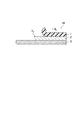
空気極(A−1)〜(A−9)及び(B−1)〜(B−14)に対し、触媒層と撥水層との密着性を評価した。図4を参照して、触媒層と撥水層との密着性の評価方法を説明する。図4に示すように、空気極10は、撥水層1と、触媒層2と、集電体3とを備えていた。空気極10の一端において、触媒層2から、撥水層1を剥がした。剥がした側の触媒層2の一端PAを固定したまま、撥水層1の一端を引っ張り方向DAに引っ張り、撥水層1を剥がし切るまでの最大張力(180°剥離強度、単位:N)を測定した。測定に使用した空気極10のサンプルの幅は55mmであり、長さは55mmであった。また、引張り速度は2mm/秒であった。剥離強度の測定結果を、表2及び表3に示す。
[Evaluation method and evaluation result]
<Evaluation of adhesion between catalyst layer and water-repellent layer>
For the air electrodes (A-1) to (A-9) and (B-1) to (B-14), the adhesion between the catalyst layer and the water-repellent layer was evaluated. With reference to FIG. 4, a method for evaluating the adhesion between the catalyst layer and the water-repellent layer will be described. As shown in FIG. 4, the
<電気特性の評価>
以下、図2を再び参照して、金属空気電池20について説明する。まず、図2に示すような金属空気電池20を作製した。金属空気電池20は、空気極10と、金属極5と、電解質4とを備えていた。正極として、空気極10(詳しくは、空気極(A−1)〜(A−9)及び(B−1)〜(B−14)の各々)を使用した。負極である金属極5として、亜鉛板を使用した。電解質4として、7Mの水酸化カリウム水溶液を使用した。
<Evaluation of electrical characteristics>
Hereinafter, the metal-
バッテリテストシステム(菊水電子工業株式会社製「PFX2011」)を用いて、作製した金属空気電池のI−V曲線特性を評価した。詳しくは、30mA/cm2の条件下で、金属空気電池の放電電圧(単位:V)を測定した。金属空気電池の作製直後(初期)の金属空気電池の放電電圧V0、及び作製から6ヶ月後の金属空気電池の放電電圧V6を、各々、測定した。放電電圧V0、及び放電電圧V6の測定結果を、表2及び表3に示す。次いで、式「低下率=100×(V0−V6)/V0」から、放電電圧の低下率(単位:%)を算出した。算出した放電電圧の低下率を、表2及び表3に示す。放電電圧の低下率が大きな値である程、経時的に放電電圧が低下し、金属空気電池の出力が低下したことを示す。作製から6ヶ月後の金属空気電池の放電電圧V6が1.00V以上であり且つ放電電圧の低下率が10.0%未満である金属空気電池を、電気特性が良好であると評価した。 Using a battery test system (“PFX2011” manufactured by Kikusui Electronics Corporation), the IV curve characteristics of the produced metal-air battery were evaluated. Specifically, the discharge voltage (unit: V) of the metal-air battery was measured under the condition of 30 mA / cm 2 . The discharge voltage V 0 of the metal-air battery immediately after the production of the metal-air battery (initial stage) and the discharge voltage V 6 of the metal-air battery six months after the production were measured. Tables 2 and 3 show the measurement results of the discharge voltage V 0 and the discharge voltage V 6 . Next, the decrease rate (unit:%) of the discharge voltage was calculated from the equation “decrease rate = 100 × (V 0 −V 6 ) / V 0 ”. Tables 2 and 3 show the calculated reduction rates of the discharge voltage. The higher the rate of decrease in the discharge voltage, the lower the discharge voltage over time, indicating that the output of the metal-air battery has decreased. A metal-air battery having a discharge voltage V 6 of 1.00 V or more and a decrease rate of the discharge voltage of less than 10.0% after six months from the production was evaluated as having good electric characteristics.
表2及び表3中の「接触角」は撥水層の水との接触角を示す。表2及び表3中の「圧着後」欄の「開孔率A2」は、各々、圧着工程後の撥水層の表面における開孔率を示す。表3中の「圧着前」欄の「開孔率A1」は、圧着工程前の撥水層の表面における開孔率を示す。表3中の「圧着後」欄の「低下率A」は、式(1)から算出される撥水層の表面における開孔率の低下率を示す。表1及び表2中の「PP」、「PE」、及び「PET」は、各々、ポリプロピレン、ポリエチレン、及びポリエステルを示す。 "Contact angle" in Tables 2 and 3 indicates the contact angle of the water-repellent layer with water. “Aperture ratio A 2 ” in the “after compression” column in Tables 2 and 3 indicates the porosity on the surface of the water-repellent layer after the compression process, respectively. “Aperture ratio A 1 ” in the “Before pressure bonding” column in Table 3 indicates the porosity on the surface of the water-repellent layer before the pressure bonding step. The “reduction rate A” in the “after pressure bonding” column in Table 3 indicates the reduction rate of the hole opening rate on the surface of the water-repellent layer calculated from the equation (1). "PP", "PE", and "PET" in Tables 1 and 2 indicate polypropylene, polyethylene, and polyester, respectively.
表2及び表3に示すように、空気極(A−1)〜(A−9)の各々において、撥水層の表面における開孔率は、30面積%以上45面積%未満であった。撥水層の水との接触角は、100度以上120度以下であった。このため、表2及び表3に示すように、空気極(A−1)〜(A−9)の各々を備える空気金属電池では、放電電圧V6が1.00V以上であり且つ放電電圧の低下率が10.0%未満であった。空気極(A−1)〜(A−9)の各々を備える金属空気電池は、出力を所望値以上に維持でき、空気金属電池の電気特性が良好であった。また、空気極(A−1)〜(A−9)では、実使用可能な程度以上に、触媒層と撥水層との密着性を有していた。 As shown in Tables 2 and 3, in each of the air electrodes (A-1) to (A-9), the porosity on the surface of the water-repellent layer was 30% by area or more and less than 45% by area. The contact angle of the water-repellent layer with water was 100 degrees or more and 120 degrees or less. Therefore, as shown in Table 2 and Table 3, the air electrode (A-1) ~ In the air-metal batteries comprising each (A-9), the discharge voltage V 6 is is and discharge voltage not less than 1.00V The reduction rate was less than 10.0%. The metal-air battery provided with each of the air electrodes (A-1) to (A-9) was able to maintain the output at or above the desired value, and the electrical characteristics of the air-metal battery were good. In the air electrodes (A-1) to (A-9), the adhesion between the catalyst layer and the water-repellent layer was higher than the practically usable degree.
一方、表2に示すように、空気極(B−1)〜(B−3)及び(B−5)〜(B−6)の各々において、撥水層の表面における開孔率が30面積%以上ではなく、撥水層の水との接触角が120度以下ではなかった。表2に示すように、空気極(B−4)において、撥水層の水との接触角が120度以下ではなかった。表2に示すように、空気極(B−7)〜(B−9)の各々において、撥水層の水との接触角が100度以上ではなかった。表3に示すように、空気極(B−10)〜(B−11)の各々において、撥水層の表面における開孔率(圧着工程後の開孔率)が、45面積%未満ではなかった。表3に示すように、空気極(B−12)〜(B−14)の各々において、撥水層の表面における開孔率(圧着工程後の開孔率)が、30面積%以上ではなかった。このため、表2及び表3に示すように、空気極(B−1)〜(B−14)の各々を備える空気金属電池では、放電電圧V6が1.00V以上であること、及び放電電圧の低下率が10.0%未満であることのうちの一方又は両方を満たさなかった。 On the other hand, as shown in Table 2, in each of the air electrodes (B-1) to (B-3) and (B-5) to (B-6), the porosity on the surface of the water-repellent layer was 30 areas. %, And the contact angle of the water-repellent layer with water was not less than 120 degrees. As shown in Table 2, at the air electrode (B-4), the contact angle of the water-repellent layer with water was not less than 120 degrees. As shown in Table 2, in each of the air electrodes (B-7) to (B-9), the contact angle of the water-repellent layer with water was not 100 degrees or more. As shown in Table 3, in each of the air electrodes (B-10) to (B-11), the porosity (the porosity after the pressure bonding step) on the surface of the water-repellent layer is not less than 45 area%. Was. As shown in Table 3, in each of the air electrodes (B-12) to (B-14), the porosity on the surface of the water-repellent layer (the porosity after the pressure bonding step) is not 30% by area or more. Was. Therefore, as shown in Table 2 and Table 3, the air-metal batteries comprising each of the air electrode (B-1) ~ (B -14), it discharge voltage V 6 is equal to or higher than 1.00 V, and discharge One or both of the voltage drop rates of less than 10.0% were not satisfied.
以上のことから、空気極(A−1)〜(A−9)を包含する本発明の空気極は、金属空気電池に備えられた場合に、金属空気電池の出力を所望値以上に維持できることが示された。また、本発明の金属空気電池は、出力を所望値以上に維持できることが示された。更に、本発明の空気極の製造方法によれば、金属空気電池の出力を所望値以上に維持できる空気極を製造できることが示された。 From the above, when the air electrode of the present invention including the air electrodes (A-1) to (A-9) is provided in a metal air battery, the output of the metal air battery can be maintained at a desired value or more. It has been shown. Moreover, it was shown that the metal-air battery of the present invention can maintain the output at or above a desired value. Furthermore, according to the method for manufacturing an air electrode of the present invention, it was shown that an air electrode capable of maintaining the output of a metal-air battery at or above a desired value can be manufactured.
本発明の空気極、及び本発明の製造方法により製造された空気極は、金属空気電池の空気極に利用できる。本発明の金属空気電池は、例えば、補聴器、携帯電話、及びデジタルカメラのような電子機器の主電源、補助電源、及び充電器に利用できる。 The air electrode of the present invention and the air electrode manufactured by the manufacturing method of the present invention can be used as an air electrode of a metal-air battery. The metal-air battery of the present invention can be used, for example, as a main power supply, an auxiliary power supply, and a charger for electronic devices such as hearing aids, mobile phones, and digital cameras.
1 :撥水層
2 :触媒層
2a :触媒層の面
2b :触媒層の面
3 :集電体
4 :電解質
5 :金属極
10 :空気極
20 :金属空気電池
31 :撥水層形成材料
1: water repellent layer 2:
Claims (9)
前記撥水層の表面における開孔率は、30面積%以上45面積%未満であり、
前記撥水層の水との接触角は、100度以上120度以下である、空気極。 A porous water-repellent layer, comprising a catalyst layer in contact with the water-repellent layer,
The porosity on the surface of the water-repellent layer is 30 area% or more and less than 45 area%,
The air electrode, wherein a contact angle of the water-repellent layer with water is 100 degrees or more and 120 degrees or less.
前記集電体は、前記撥水層と接触している前記触媒層の面とは反対側の前記触媒層の面と接触している、請求項1〜4の何れか一項に記載の空気極。 Further comprising a current collector,
The air according to claim 1, wherein the current collector is in contact with a surface of the catalyst layer opposite to a surface of the catalyst layer that is in contact with the water-repellent layer. very.
前記撥水層と前記触媒層とを圧着する圧着工程とを含む、請求項1〜5の何れか一項に記載の空気極の製造方法。 A water-repellent layer forming step of stretching the water-repellent layer forming material to form the water-repellent layer;
The method for producing an air electrode according to claim 1, further comprising a pressure bonding step of pressing the water-repellent layer and the catalyst layer.
下記式(1)から算出される前記撥水層の前記表面における開孔率の低下率Aは、20.0%以上である、請求項7又は8に記載の空気極の製造方法。
A=100×(A1−A2)/A1・・・(1)
(前記式(1)中、A1は前記圧着工程の前の前記撥水層の前記表面における開孔率を表し、A2は前記圧着工程の後の前記撥水層の前記表面における開孔率を表す。) In the pressure bonding step, by applying pressure to the water-repellent layer, the porosity on the surface of the water-repellent layer is reduced, and the porosity on the surface of the water-repellent layer is increased by 30% by area or more. Adjust to less than area%,
The method for producing an air electrode according to claim 7, wherein a decrease rate A of the porosity on the surface of the water-repellent layer calculated from the following formula (1) is 20.0% or more.
A = 100 × (A 1 −A 2 ) / A 1 (1)
(In the formula (1), A 1 represents the porosity on the surface of the water-repellent layer before the pressure-bonding step, and A 2 represents the aperture on the surface of the water-repellent layer after the pressure-bonding step. Rate.)
Priority Applications (3)
| Application Number | Priority Date | Filing Date | Title |
|---|---|---|---|
| JP2018126836A JP7112268B2 (en) | 2018-07-03 | 2018-07-03 | Method for manufacturing air electrode and method for manufacturing metal-air battery |
| US16/446,302 US20200014035A1 (en) | 2018-07-03 | 2019-06-19 | Air electrode, metal-air battery, and method for manufacturing air electrode |
| CN201910569597.4A CN110676465B (en) | 2018-07-03 | 2019-06-27 | Air electrode, metal-air battery, and method for manufacturing air electrode |
Applications Claiming Priority (1)
| Application Number | Priority Date | Filing Date | Title |
|---|---|---|---|
| JP2018126836A JP7112268B2 (en) | 2018-07-03 | 2018-07-03 | Method for manufacturing air electrode and method for manufacturing metal-air battery |
Publications (2)
| Publication Number | Publication Date |
|---|---|
| JP2020009545A true JP2020009545A (en) | 2020-01-16 |
| JP7112268B2 JP7112268B2 (en) | 2022-08-03 |
Family
ID=69068812
Family Applications (1)
| Application Number | Title | Priority Date | Filing Date |
|---|---|---|---|
| JP2018126836A Active JP7112268B2 (en) | 2018-07-03 | 2018-07-03 | Method for manufacturing air electrode and method for manufacturing metal-air battery |
Country Status (3)
| Country | Link |
|---|---|
| US (1) | US20200014035A1 (en) |
| JP (1) | JP7112268B2 (en) |
| CN (1) | CN110676465B (en) |
Citations (7)
| Publication number | Priority date | Publication date | Assignee | Title |
|---|---|---|---|---|
| JPS58198862A (en) * | 1982-05-17 | 1983-11-18 | Toshiba Corp | Manufacturing method of cylindrical air electrode |
| JPS5994374A (en) * | 1982-11-22 | 1984-05-31 | Toshiba Corp | Cylindrical air electrode |
| JPS6261275A (en) * | 1985-09-12 | 1987-03-17 | Toshiba Corp | Air cell |
| JPS6231788B2 (en) * | 1981-05-29 | 1987-07-10 | Hitachi Seisakusho Kk | |
| JPH06338355A (en) * | 1993-05-28 | 1994-12-06 | Toshiba Battery Co Ltd | Air cell |
| JP2005523566A (en) * | 2002-04-16 | 2005-08-04 | ゴア エンタープライズ ホールディングス,インコーポレイティド | Electrochemical equipment alignment film |
| JP2017033650A (en) * | 2015-07-29 | 2017-02-09 | 日本バルカー工業株式会社 | Gas diffusion film / water repellent film laminate, air electrode and fuel cell using the same, and method for producing gas diffusion film / water repellent film laminate |
Family Cites Families (17)
| Publication number | Priority date | Publication date | Assignee | Title |
|---|---|---|---|---|
| CA1208168A (en) * | 1980-10-31 | 1986-07-22 | Eltech Systems Corporation | Producing electrode active layer from active carbon particles and fibrillated polytetrafluoroethylene |
| JPH0665039B2 (en) * | 1986-07-03 | 1994-08-22 | 株式会社日立製作所 | Fuel cell using three-layer gas diffusion electrode |
| JP3034110B2 (en) * | 1991-12-16 | 2000-04-17 | 日東電工株式会社 | Water repellent film |
| JP3686139B2 (en) * | 1995-10-16 | 2005-08-24 | 東芝電池株式会社 | Alkaline secondary battery |
| CN1190859C (en) * | 1998-08-20 | 2005-02-23 | 松下电器产业株式会社 | Fuel cell and manufacture thereof |
| JP3941031B2 (en) * | 1999-11-18 | 2007-07-04 | 五郎 山内 | Waterproof electroacoustic transducer |
| CN100562353C (en) * | 2004-10-21 | 2009-11-25 | 松下电器产业株式会社 | Oxygen permeable membrane, oxygen permeable sheet and battery comprising the same |
| JP2008041521A (en) * | 2006-08-09 | 2008-02-21 | Matsushita Electric Ind Co Ltd | Air battery |
| JP4323535B2 (en) * | 2007-04-26 | 2009-09-02 | クロリンエンジニアズ株式会社 | Water electrolysis equipment |
| JP5822428B2 (en) * | 2009-01-20 | 2015-11-24 | 大日本印刷株式会社 | Gas diffusion layer and polymer electrolyte fuel cell using the same |
| JP5481330B2 (en) * | 2009-09-11 | 2014-04-23 | 帝人株式会社 | Non-aqueous electrolyte battery manufacturing method, core used for manufacturing non-aqueous electrolyte battery |
| MX2014015166A (en) * | 2012-06-12 | 2015-08-14 | Univ Monash | Gas permeable electrode and method of manufacture. |
| JP6474977B2 (en) * | 2013-08-30 | 2019-02-27 | 日東電工株式会社 | Waterproof ventilation membrane, waterproof ventilation member, waterproof ventilation structure and waterproof sound-permeable membrane including the same |
| JP2015220099A (en) * | 2014-05-19 | 2015-12-07 | Tdk株式会社 | All solid lithium ion secondary battery |
| JP6775316B2 (en) * | 2016-04-20 | 2020-10-28 | 日本バイリーン株式会社 | Membrane-electrode assembly and polymer electrolyte fuel cell |
| CN106611858B (en) * | 2016-12-20 | 2019-12-06 | 云南创能斐源金属燃料电池有限公司 | carbon-free air electrode and preparation method thereof |
| CN108183241A (en) * | 2017-12-29 | 2018-06-19 | 张树雄 | A kind of air electrode and its catalysis slurry preparation method |
-
2018
- 2018-07-03 JP JP2018126836A patent/JP7112268B2/en active Active
-
2019
- 2019-06-19 US US16/446,302 patent/US20200014035A1/en not_active Abandoned
- 2019-06-27 CN CN201910569597.4A patent/CN110676465B/en active Active
Patent Citations (7)
| Publication number | Priority date | Publication date | Assignee | Title |
|---|---|---|---|---|
| JPS6231788B2 (en) * | 1981-05-29 | 1987-07-10 | Hitachi Seisakusho Kk | |
| JPS58198862A (en) * | 1982-05-17 | 1983-11-18 | Toshiba Corp | Manufacturing method of cylindrical air electrode |
| JPS5994374A (en) * | 1982-11-22 | 1984-05-31 | Toshiba Corp | Cylindrical air electrode |
| JPS6261275A (en) * | 1985-09-12 | 1987-03-17 | Toshiba Corp | Air cell |
| JPH06338355A (en) * | 1993-05-28 | 1994-12-06 | Toshiba Battery Co Ltd | Air cell |
| JP2005523566A (en) * | 2002-04-16 | 2005-08-04 | ゴア エンタープライズ ホールディングス,インコーポレイティド | Electrochemical equipment alignment film |
| JP2017033650A (en) * | 2015-07-29 | 2017-02-09 | 日本バルカー工業株式会社 | Gas diffusion film / water repellent film laminate, air electrode and fuel cell using the same, and method for producing gas diffusion film / water repellent film laminate |
Also Published As
| Publication number | Publication date |
|---|---|
| US20200014035A1 (en) | 2020-01-09 |
| CN110676465A (en) | 2020-01-10 |
| CN110676465B (en) | 2023-06-06 |
| JP7112268B2 (en) | 2022-08-03 |
Similar Documents
| Publication | Publication Date | Title |
|---|---|---|
| EP4235891A2 (en) | Separator for non-aqueous secondary battery, and non-aqueous secondary battery | |
| JP6070671B2 (en) | Air battery | |
| US6368365B1 (en) | Method of making a battery | |
| JP2588523B2 (en) | Carbon electrode | |
| US6921606B2 (en) | Composite films for electrochemical devices | |
| US10950910B2 (en) | Air cell and patch | |
| CN113474925B (en) | Negative electrode and sheet battery for aqueous electrolyte battery | |
| JP2019216084A (en) | Gas diffusion layer for fuel cell, membrane electrode assembly, and fuel battery | |
| JP6360531B2 (en) | Non-aqueous electrolyte secondary battery laminated separator, non-aqueous electrolyte secondary battery member, and non-aqueous electrolyte secondary battery | |
| CN116391275A (en) | Positive electrode active material for secondary battery, manufacturing method thereof, self-supporting film including same, dry electrode, and secondary battery including dry electrode | |
| JP6927869B2 (en) | Method for manufacturing catalyst layer, air electrode, metal-air battery and catalyst layer | |
| JP5193478B2 (en) | Gas diffusion electrode, membrane-electrode assembly and method for producing the same, and polymer electrolyte fuel cell | |
| CN118786547A (en) | Mixture for secondary battery, mixture sheet for secondary battery, method for producing the same, and secondary battery | |
| JP2022019433A (en) | Laminate for nonaqueous electrolyte solution secondary battery | |
| CN113809349A (en) | Gas diffusion layer, membrane electrode assembly, fuel cell, and method for producing gas diffusion layer | |
| JP6947565B2 (en) | Manufacturing method of air electrode, metal-air battery and air electrode | |
| JP5182908B2 (en) | Membrane electrode assembly and fuel cell | |
| JP7657554B2 (en) | Secondary battery | |
| TW201721946A (en) | Gas diffusion electrode and method for producing same | |
| JP7112268B2 (en) | Method for manufacturing air electrode and method for manufacturing metal-air battery | |
| JP2007128671A (en) | Gas diffusion electrode, membrane-electrode assembly and method for producing the same, and polymer electrolyte fuel cell | |
| JPS6319979B2 (en) | ||
| JP2007179870A (en) | Gas diffusion electrode, membrane-electrode assembly, polymer electrolyte fuel cell, and production method thereof | |
| KR20120106137A (en) | Manufacturing method of manganese oxide catalyst using multi wall carbon nano tube for zinc-air battery and manufacturing method of cathode for zinc-air battery using thereof | |
| CN107645024B (en) | Air Electrode Materials, Air Electrodes, Metal Air Batteries and Fuel Cells |
Legal Events
| Date | Code | Title | Description |
|---|---|---|---|
| A621 | Written request for application examination |
Free format text: JAPANESE INTERMEDIATE CODE: A621 Effective date: 20210324 |
|
| A977 | Report on retrieval |
Free format text: JAPANESE INTERMEDIATE CODE: A971007 Effective date: 20220125 |
|
| A131 | Notification of reasons for refusal |
Free format text: JAPANESE INTERMEDIATE CODE: A131 Effective date: 20220301 |
|
| A521 | Request for written amendment filed |
Free format text: JAPANESE INTERMEDIATE CODE: A523 Effective date: 20220420 |
|
| TRDD | Decision of grant or rejection written | ||
| A01 | Written decision to grant a patent or to grant a registration (utility model) |
Free format text: JAPANESE INTERMEDIATE CODE: A01 Effective date: 20220628 |
|
| A61 | First payment of annual fees (during grant procedure) |
Free format text: JAPANESE INTERMEDIATE CODE: A61 Effective date: 20220722 |
|
| R150 | Certificate of patent or registration of utility model |
Ref document number: 7112268 Country of ref document: JP Free format text: JAPANESE INTERMEDIATE CODE: R150 |